1
Configuration
7
This chapter describes the System Control Coprocessor (CP15) and coprocessor 14 (CP14). CP15
configures the MMU, caches, buffers and other system attributes. Where possible, the definition of
CP15 follows the definition of ARM* v5 products, see the ARM* Architecture Reference Manual
for details. The PXA250 and PXA210 applications processors also include various extra devicespecific configuration capabilities which are described here. CP14 contains the performance
monitor registers and the trace buffer registers.
7.1
Overview
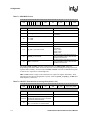
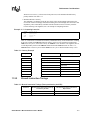
CP15 is accessed through MRC and MCR coprocessor instructions whose format is shown in
Table 7-1, “MRC/MCR Format” on page 7-2. These instructions transfer data between ARM*
registers and coprocessor registers. Coprocessor access is only allowed in a privileged mode. Any
access to CP15 in user mode or with LDC or STC coprocessor instructions will cause an
Undefined Instruction exception.
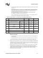
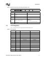
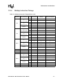
CP14 registers can be accessed through MRC, MCR, LDC, and STC coprocessor instructions and
allowed only in privileged mode. LDC and STC transfer data between memory and coprocessor
registers. See Table 7-2, “LDC/STC Format when Accessing CP14” on page 7-2. Any access to
CP14 in user mode will cause an Undefined Instruction exception.
Coprocessors CP15 and CP14 on the Intel® XScale™ core do not support access via CDP,
MRRC, or MCRR instructions. An attempt to access these coprocessors with these instructions
will result in an Undefined Instruction exception.
Many of the MCR commands available in CP15 modify hardware state sometime after execution.
A software sequence is available for those wishing to determine when this update occurs and can
be found in Section 2.3.3, “Additions to CP15 Functionality” on page 2-10.
As in the Intel® SA-1110 product, and ARM* v5 Architecture specification, the Intel® XScale™
core includes an extra level of virtual address translation in the form of a PID (Process ID) register
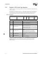
and associated logic. For a detailed description of this facility, see Section 7.2.11, “Register 13:
Process ID” on page 7-12. Privileged code needs to be aware of this facility because when
interacting with CP15 some addresses are modified by the PID and others are not.
An address that has yet to be modified by the PID is known as a virtual address (VA). An address
that has been through the PID logic, but not translated into a physical address, is a modified virtual
address (MVA). Non-privileged code always deals with VAs, while privileged code that programs
CP15 occasionally needs to use MVAs.
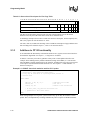
The format of MRC and MCR, that move data to and from coprocessor registers, is shown in
Table 7-1.
cp_num is defined for CP15, CP14 and CP0 on the Intel® XScale™ core. CP0 supports
instructions specific for DSP and is described in Chapter 2, “Programming Model.”
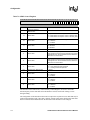
Unless otherwise noted, unused bits in coprocessor registers have unpredictable values when read.
For compatibility with future implementations, software must program these bits as zero.
Intel® XScale™ Microarchitecture User’s Manual
7-1