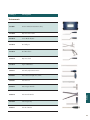
1
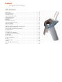
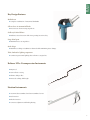
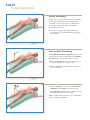
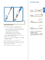
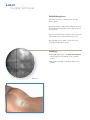
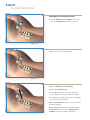
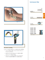
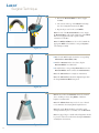
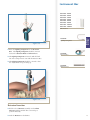
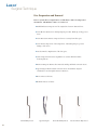
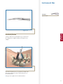
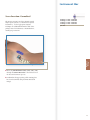
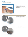
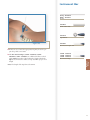
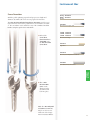
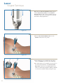
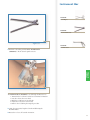
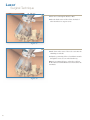
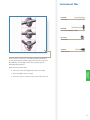
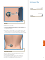
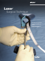
Spine
Luxor
™
Surgical Technique
• Minimally invasive procedures
• Luminated expandable oval
retractor
• Complete visualization and
optimal working space
™
LITe
Less Invasive Technologies
Luxor
™
Surgical Technique
Table of Contents
Introduction . . . . . . . . . . . . . . . . . . . . . . . . . . . . . . . . . . . . . . . . . . . . . . . . . . . . . . . . . . . .4
Key Design Features . . . . . . . . . . . . . . . . . . . . . . . . . . . . . . . . . . . . . . . . . . . . . . . . . . . . . .5
Patient Positioning . . . . . . . . . . . . . . . . . . . . . . . . . . . . . . . . . . . . . . . . . . . . . . . . . . . . . . .6
Arm Assembly Positioning . . . . . . . . . . . . . . . . . . . . . . . . . . . . . . . . . . . . . . . . . . . . . . . .6
Lighting Preparation . . . . . . . . . . . . . . . . . . . . . . . . . . . . . . . . . . . . . . . . . . . . . . . . . . . . .7
Establishing Access . . . . . . . . . . . . . . . . . . . . . . . . . . . . . . . . . . . . . . . . . . . . . . . . . . . . . . .8
Markings . . . . . . . . . . . . . . . . . . . . . . . . . . . . . . . . . . . . . . . . . . . . . . . . . . . . . . . . . . . . . . .8
Initial Dilator Insertion . . . . . . . . . . . . . . . . . . . . . . . . . . . . . . . . . . . . . . . . . . . . . . . . . .10
Subsequent Dilator Insertion . . . . . . . . . . . . . . . . . . . . . . . . . . . . . . . . . . . . . . . . . . . . .12
Retractor Assembly . . . . . . . . . . . . . . . . . . . . . . . . . . . . . . . . . . . . . . . . . . . . . . . . . . . . .13
Retractor Insertion . . . . . . . . . . . . . . . . . . . . . . . . . . . . . . . . . . . . . . . . . . . . . . . . . . . . . .15
Retractor Variable Opening/Closing Mechanism . . . . . . . . . . . . . . . . . . . . . . . . . . . . .16
Disc Preparation and Removal . . . . . . . . . . . . . . . . . . . . . . . . . . . . . . . . . . . . . . . . . . . .18
Disc Preparation and Removal Continued . . . . . . . . . . . . . . . . . . . . . . . . . . . . . . . . . .20
Interbody Fusion . . . . . . . . . . . . . . . . . . . . . . . . . . . . . . . . . . . . . . . . . . . . . . . . . . . . . . .21
Graft Insertion . . . . . . . . . . . . . . . . . . . . . . . . . . . . . . . . . . . . . . . . . . . . . . . . . . . . . . . . .22
Screw Insertion: Cannulated . . . . . . . . . . . . . . . . . . . . . . . . . . . . . . . . . . . . . . . . . . . . . .23
Screw Insertion: Non-Cannulated . . . . . . . . . . . . . . . . . . . . . . . . . . . . . . . . . . . . . . . . .31
Rod Insertion . . . . . . . . . . . . . . . . . . . . . . . . . . . . . . . . . . . . . . . . . . . . . . . . . . . . . . . . . .33
Blocker Insertion . . . . . . . . . . . . . . . . . . . . . . . . . . . . . . . . . . . . . . . . . . . . . . . . . . . . . . .37
Construct Tightening . . . . . . . . . . . . . . . . . . . . . . . . . . . . . . . . . . . . . . . . . . . . . . . . . . . .40
Closure . . . . . . . . . . . . . . . . . . . . . . . . . . . . . . . . . . . . . . . . . . . . . . . . . . . . . . . . . . . . . . .41
Contralateral Side . . . . . . . . . . . . . . . . . . . . . . . . . . . . . . . . . . . . . . . . . . . . . . . . . . . . . . .41
Catalog . . . . . . . . . . . . . . . . . . . . . . . . . . . . . . . . . . . . . . . . . . . . . . . . . . . . . . . . . . . . . . .42
Removal or Revision Procedures . . . . . . . . . . . . . . . . . . . . . . . . . . . . . . . . . . . . . . . . . .46
Notes . . . . . . . . . . . . . . . . . . . . . . . . . . . . . . . . . . . . . . . . . . . . . . . . . . . . . . . . . . . . . . .47
Luxor
™
Surgical Technique
Acknowledgments
Stryker® Spine wishes to thank the global Luxor™ Surgeon Panel for their dedication
to the development of the Luxor™ System.
Introduction
The objective of Stryker Spine Less Invasive Technologies (LITe™) is to replicate
the clinical results of the corresponding open procedure. What sets the minimally
invasive procedures apart from open procedures is that while delivering similar
clinical results, these procedures offer reduced intraoperative blood loss*, reduced
post operative mobilization times*, and the potential for minimized postoperative
consumption of orally administered narcotics*.
The Luxor™ Retractor, part of the LITe™ platform, was designed to provide access
to the thoracic and lumbar spine from a posterior approach via a small incision.
The oval design of Luxor™ reduces the medial/lateral muscle retraction seen in some
circular retractors, while providing more working space at the level of the incision.
Important
This Surgical Technique sets forth detailed, recommended procedures for using
the Luxor™ System. It offers guidance that you should heed but, as with any such
technical guide, each surgeon must consider the particular needs of each patient
and make appropriate adjustments when necessary and as required.
Always refer to the package insert, product label and/or instructions before using
any Stryker implant or instrument.
Note: No acid or alkaline solvents should be used in the cleaning of anodized
components.
Note: Upon the completion of each surgical procedure, use adequate suction and
irrigation to ensure the removal of any existing non-implantable materials.
Note: This is intended as a guide only. There are multiple techniques, and as with
any surgical procedure, a surgeon should be thoroughly trained before proceeding.
4
*Data on file at Stryker Spine
Key Design
Features
Key Design Features
Radiolucent
> Complete visualization of anatomical landmarks
Silicon sleeve & Anatomical blades
> Prevent tissue from entering surgical site
Cobb-style initial dilator
> Facilitates tissue dissection while incorporating insertion safety
Large distal span
> Maximum access at surgical site
Oval design
> Maximizes working & visualization channels while minimizing tissue damage
Thin, shadowless lighting component
> Continuous panoramic lighting that conforms to surgical site
Reliance LITe™ Decompression Instruments
> Bayoneted
> Non-reflective coating
> Thinner shaft profiles
> Increased working shaft length
Fixation Instruments
> Accommodates Cannulated and Non-Cannulated screws
> Rod insertion
> Blocker insertion
> Construct adjustment and final tightening
5
Luxor
™
Surgical Technique
Patient Positioning
Luxor™ can be used successfully under local, epidural,
spinal or general anesthesia. General anesthesia is
commonly used since it is the most comfortable for
the patient and allows immediate postoperative
neurological assessment.
> The patient is prepped and draped in the usual
sterile manner for posterolateral fusion with pedicle
screw fixation.
Figure 1
Arm Assembly Positioning
The Mediflex Flex Arm Post (48250240) mounts to the
hospital bed rail. Check compatibility of the Mediflex
Flex Arm Post to the hospital bed prior to surgery.
> Mount the Arm Post to the bed rail on the opposite
side of the surgeon near the patient’s hip.
> Turn the Arm Post locking mechanism clockwise to
secure it to the bed.
Figure 2
> Once the Arm Post is secure, attach the Snake Arm
(48250230) to the Arm Post and lock into place.
> The Snake Arm should be positioned to lie across the
patient and wrap in front of the surgeon.
Note: For additional information, see the Mediflex Flex
Arms™ Surgical User’s Manual.
Figure 3
6
48250240
Arm Post
Patient
Prep
Instrument Bar
48250230
Snake Arm
Figure 4
48250215
Universal Light Cable
Lighting Preparation
> Determine the type of light source available in the OR.
> Choose the corresponding Luxor™ Lightsource Adapter:
48250210
Lighting Component
• Stryker / ACMI / Zimmer Lightsource Adapter (233-050-071)
• Storz Lightsource Adapter (233-050-073)
• Olympus Lightsource Adapter (233-050-072)
• Wolf / Dyonics Lightsource Adapter (233-050-074)
> Attach the Universal Light Cable (48250215) to the appropriate
Adapter and insert into the light source.
233-050-071 - Stryker/ACMI/Zimmer
233-050-073 - Storz
233-050-072 - Olympus
233-050-074 - Wolf/Dyonics
Lightsource Adapters
> Attach the other end of the Universal Light Cable to the Lighting
Component (48250210).
> Turn on the light source power to verify light output.
Note: the Universal Light Cable is made of clear fiber optics. This is
designed to easily identify broken fibers. If light output is low this
instrument may need to be replaced.
Note: The Lighting Component is a single use instrument.
7
Luxor
™
Surgical Technique
Establishing Access
A/P images are used to confirm placement of the
Luxor™ System.
The Retractor Base is delivered via a dilation system at
approximately the same angle as the pedicle screws are
to be inserted.
Upon insertion, the Luxor™ retractor exposes portions
of the lamina, facet joints, and transverse process.
The following steps are taken to assure the correct
positioning of the Luxor™ System.
Markings
> Using A/P imaging, place the Guide Pin (48250010)
transversely across the mid-line of the cephalad
pedicles.
> Draw a line extending several inches lateral to the
pedicles.
Figure 5
8
48250010
Guide Pin
Patient
Prep
Instrument Bar
Figure 6
> Repeat for the caudal pedicles.
9
Luxor
™
Surgical Technique
Carefully determine the appropriate entry point and
trajectory for the Luxor™.
> For decompression, the entry point is approximately
2cm off mid-line with a more medial trajectory.
> For pedicle screws, the entry point is approximately
4cm off mid-line with a more lateral trajectory.
Note: The entry point is typically at or cephalad to the
accessory process (AP) on the transverse process.
> A 3.5cm incision parallel to the spine is made at the
puncture site.
> Incise the fascia to make tissue dilation easier.
Figure 7
Note: For procedures not requiring distal expansion of
the retractor, a 3.0cm incision can be used for insertion.
Note: If tissue dilation is difficult increase the fascial
incision.
Initial Dilator Insertion
> Place the cobb style Initial Dilator (48250011)
through the incision.
> Advance the Dilator through the tissue while
directing it toward the inferior aspect of the superior
lamina under lateral imaging.
> The Dilator is advanced through the lumbodorsal
fascia.
> Location of the cobb style Initial Dilator is
confirmed using imaging.
Figure 8
> Note the depth marking of the Dilator in relation to
the skin.
The Dilators have depth markings (40, 50, 60, 70, 80,
90, 105, 120mm) laser etched which correlate to
retractor blade lengths.
> Choose a Retractor Blade length (48250(040)-(120))
based on where the top of the skin meets the Dilator.
Note: If the skin is between two markings on the
Dilator choose the next longest Blade.
10
Instrument Bar
Figure 9
48250040 - 40mm
48250050 - 50mm
48250060 - 60mm
48250070 - 70mm
48250080 - 80mm
48250090 - 90mm
48250105 - 105mm
48250120 - 120mm
Retractor Blades
Dilation
Insertion
48250011
Cobb Style Initial Dilator
> Use the cobb style Initial Dilator to palpate the lamina in
both the sagittal and transverse planes. This confirms an
appropriate approach laterally.
> The tip of the Dilator is used to sweep the paraspinal
musculature off the laminar edge.
Note: The Dilator (22mm width) is designed not to enter
the intralaminar space when oriented cephalo-caudal.
Note: By keeping the Dilator tip in the subperiosteal space,
the dissection is essentially bloodless.
Note: Feel, fluoroscopy, anatomical knowledge, review
of preoperative images, and partial visualization may all
contribute towards desired instrument placement accuracy.
Note: Great care must be taken to avoid penetration of the
ligamentum flavum and inadvertent dural puncture with
possible nerve injury or spinal fluid leak.
Note: If using the Guide Pin do not direct it lateral to the
lamina or facet, which risks injury to the nerve root or
deeper structures.
Note: To ensure that the Guide Pin was not bent during a
prior surgical procedure, pass the Guide Pin through the
cannulation in the cobb style Initial Dilator. This activity
confirms that the Guide Pin is not bent, and reduces the
risk of the Guide Pin being advanced forward into the
canal space when used through the cobb style Initial Dilator
during the dilation process.
11
Luxor
™
Surgical Technique
Subsequent Dilator Insertion
> Slide the Kelly Retractors (48250017) around the
cobb style Initial Dilator and into the incision.
Figure 10
> Remove the cobb style Initial Dilator.
Figure 11
> Insert the Blunt Dissector (48250018).
> Remove the Kelly Retractors.
> Use the Blunt Dissector to penetrate and gently
spread and dissect soft tissue down to the lamina.
> Use imaging to confirm the placement of the Blunt
Dissector on the superior facet.
Note: The Blunt Dissector may be used to probe and
identify the anatomy.
Figure 12
12
Note: If additional assistance is needed introducing
the Blunt Dissector, use both the Kelly Retractors
(48250017) together to facilitate introduction.
Instrument Bar
Dilation
Insertion
48250017
Kelly Retractors
48250018
Blunt Dissector
Figure 13
48250020
Retractor Base
48250040 - 40mm
48250050 - 50mm
48250060 - 60mm
48250070 - 70mm
48250080 - 80mm
48250090 - 90mm
48250105 - 105mm
48250120 - 120mm
Retractor Blades
Figure 14
Retractor Assembly
Assemble each Retractor Blade into the Retractor Base (48250020)
1. Orient the Retractor Base so that the variable driving screw
and post are pointing up.
2. Align the hole in the proximal end of the Retractor Blade
with the pin in the Retractor Base.
3. Lightly squeeze the Retractor Blade on the proximal edges
and insert the Retractor Blade into the Retractor Base.
13
Luxor
™
Surgical Technique
4. Release the Retractor Blade so that it engages
the Base.
5. The cutouts at the top of the Blade should snap
into the rectangular features in the Base.
6. Repeat the process for the second Blade.
Note: If a side of the Retractor Blade does not engage
the Retractor Base, push on the 1mm edge of the Blade
that is not engaged toward the cephalo-caudal
orientation of the Base.
Note: The Blades and Base are color coded. Match the
appropriate Blade color with the corresponding Base
color during assembly.
Figure 15
> Based on the Blade length, obtain the corresponding
Silicon Sleeve (48251(040)-(120).
> With the Retractor in the closed state, dip the
Retractor Blades in a saline bath.
> Slowly slide the corresponding Silicon Sleeve onto the
Retractor Blades until it contacts the Retractor Base.
Note: The Silicon Sleeve is a single use instrument.
Note: The Silicon Sleeve should be slightly longer than
the longest Retractor Blade being used.
Figure 16
Note: In cases where the Retractor cannot be actuated
due to docking on bone, using Blades of different
length is recommended.
Note: The Silicon Sleeve may need to be cut or altered
to accommodate the varying blade lengths chosen.
Note: The sterile Sleeve should be cut with a sterile
cutting instrument prior to assembly onto the Retractor .
Note: No jagged edges or visible silicon fragments should
be present on the Sleeve when introducing the Retractor
assembly into the incision.
Figure 17
14
Instrument Bar
48250210
Lighting Component
Figure 18
> Insert the Lighting Component into the Retractor
Base. The Lighting Component should be inserted
between the Retractor Blade and Silicon Sleeve.
> The Lighting Component is inserted until the black
bar on the Component is even with the Retractor Base.
Retractor
Insertion
48251040 - 40mm
48251050 - 50mm
48251060 - 60mm
48251070 - 70mm
48251080 - 80mm
48251090 - 90mm
48251105 - 105mm
48251120 - 120mm
Silicone Sleeve
48250020
Retractor Base
> The Lighting Component should be oriented so that
the “Stryker LITe™” logo is facing up.
48250018
Blunt Dissector
Figure 19
Retractor Insertion
> Slide the closed Retractor assembly over the Blunt
Dissector with the variable drive screw and post
positioned laterally.
> Dock the Retractor on the lamina.
15
Luxor
™
Surgical Technique
> Attach the Snake Arm to the Retractor Base.
> Lock the Snake Arm to the Retractor Base post by
turning the collet.
> Secure the Arm Assembly by tightening the knobs.
> Remove the Blunt Dissector. This establishes an oval
operative corridor to the lamina and interlaminar
space.
> Use imaging to confirm appropriate positioning.
Figure 20
Note: If repositioning of the Retractor is necessary to
expose the laminar edge, use the Driver (48250200) to
collapse the Retractor. The Retractor can then be
moved or angled over the pathology using the cobb
style Initial Dilator. Once in the proper location, the
Arm Assembly is tightened.
Retractor Variable Opening/Closing
Mechanism
> Insert the Driver (48250200) into the post of the
Retractor Base and screw down (clockwise) the
variable drive screw to expand the distal end of the
Retractor Blades.
> If necessary, gently rock the Retractor Base in the
cephalo-caudal direction during expansion.
Figure 21
16
Instrument Bar
48250230
Snake Arm
Figure 22
48250018
Blunt Dissector
Retractor
Insertion
48250020
Retractor Base
> Confirm expansion and position of the Luxor™ System
with imaging.
Note: Distal opening of the Retractor is dependant on the
Blade length. There is a mechanical stop in the Retractor
base with a maximum opening of 22.5 degrees.
This correlates to:
Blade
Length
Retractor
Distal Span
with Silicon
(mm)
Maximum
Rod
Length
(mm)
40
58
55
50
63
60
60
68
65
70
75
70
80
79
75
90
82
80
105
80
80
120
78
75
(mm)
48250200
Driver
17
Luxor
™
Surgical Technique
Disc Preparation and Removal
Luxor™ System offers a comprehensive set of Reliance™ LITe™ decompression
instruments. This Reliance™ LITe™ set consists of:
> Penfield Elevators: Inspection of the surgical site between dura and bone.
> Nerve Hooks: Retract nerve during surgical procedure. Blunt tip to help protect
nerve.
> Nerve Retractors: Retract compressed nerve root away from disc space.
> Nerve Probes: Inspection of the surgical site. The ball tip helps to prevent
damage of the nerve.
> Woodson Probes: Exploration of the disc space.
> Suction Tips: Provide suction capabilities to evacuate fluid and debris
from surgical site.
> Kerrison Rongeurs: Remove disc material, cartilage and hard connective tissue.
> Sypert Rongeur: Remove hard connective tissue. Instrument designed
exclusively for use through the Luxor™ Retractor.
> Bovie: Dissect soft tissue.
> Bi-Polar: Dissect soft tissue.
Penfield Bayoneted
18
Sypert Rongeur
Nerve Hook Bayoneted,
Woodson Probe Bayoneted
These instruments are designed with:
> Bayoneted working shafts provide greater visibility while working through the
Retractor.
> Working lengths of the 16cm or more for surgical procedures in the lower
posterior thoracic and lumbar spine.
> Non-reflective coating to further increase visibility by reducing glare, while
working through the Retractor.
> Handle profiles and shaft diameters minimized to provide greater visibility.
Disc Prep
and Removal
> Tips rounded for safety.
Ball Probe Bayoneted
Nerve Root Retractor
Suction Tip with Bend
Micro Scissor
19
Luxor
™
Surgical Technique
Disc Preparation and Removal
Continued
> Identify the offending disc material.
> Enter the disc space at the vertebral margins.
> Resect the posterior lip of the vertebral body.
This will simultaneously help free the cartilagenous
endplate and provide direct entry to the disc space.
Figure 23
> Remove the offending disc material with a Sypert
Rongeur (48247001).
> Intradiscal and extradiscal work can be executed, as
one would normally perform during a
microdiscectomy.
Figure 24
> The nerve root and spinal canal are explored to
ensure the decompression is complete.
> Once the nerve root is decompressed, irrigate the disc
space thoroughly.
Figure 25
20
Instrument Bar
48247001
Sypert Ronguer
Interbody Fusion
A shaver (TPS Saber; Stryker Endoscopy) is ideal to free
the cartilagenous endplates while preserving the bony
endplate.
Disc Prep
and Removal
Figure 26
Figure 27
If an Interbody Fusion is to be performed, complete the
discectomy, leaving the anterior and lateral aspects of
the annulus intact.
> Prepare the endplate for the interbody fusion.
21
Luxor
™
Surgical Technique
Graft Insertion
> Once the disc space is meticulously prepared, insert
cancellous bone into the disc space using angled and
straight forceps.
Figure 28
> Subsequently, use available bone tamps to impact the
cancellous bone. The anterior longitudinal ligament
and remaining annulus will contain the graft.
Figure 29
> Insert the allograft. Carefully use an angled
osteotome or bone tamp to slide the allograft.
The chamfered edge facilitates this maneuver.
> Pack additional cancellous bone medial to the first
graft, then insert the second graft.
> To achieve a posterolateral fusion, decorticate the
facet, pars, transverse processes and sacral ala using a
burr, chisels, curettes, kerrisons, and/or rongeurs in
the normal manner.
> Place the bone graft over the decorticated bone in the
usual manner.
Figure 30
22
Instrument Bar
Screw Insertion: Cannulated
Figure 31
10 Gauge, 9
10 Gauge, 5
11 Gauge, 5
13 Gauge, 5
Jam Shidi
inch
inch
inch
inch
48237110
48237105
48237115
48237135
Pedicle
Prep
The Luxor™ System is used in conjunction with
Stryker Spine systems (i.e., Xia Precision System,
Techtonix™). See the appropriate Surgical
Technique for additional information and device
package insert for indications, contraindications,
warnings & precautions.
> Insert the Jam Shidi 48237 (105), (110), (115), (135)
through the Luxor™ Retractor to the intersection of
the facet and transverse process.
> Confirm that the appropriate pedicle starting place
has been determined using both A/P and lateral
images.
23
Luxor
™
Surgical Technique
Use the Jam Shidi needle to gain access to the pedicle.
> After placing the Jam Shidi at the intersection of the
facet and the transverse process, the needle may be
advanced partially through the pedicle using the Slap
Hammer (48237120).
Figure 32
> As the pedicle is navigated with the Jam Shidi, it
should approach the medial wall of the pedicle on
the A/P view and should approach the base of the
pedicle on the lateral view.
Figures 33A & 33B
> When the needle reaches the medial wall on the A/P
view, verification needs to be performed in the lateral
view to ensure the needle is past the base of the
pedicle.
Figures 34A & 34B
24
Instrument Bar
10 Gauge, 9
10 Gauge, 5
11 Gauge, 5
13 Gauge, 5
Jam Shidi
inch
inch
inch
inch
48237110
48237105
48237115
48237135
48237120
Slap Hammer
Figure 35
Sharp 48230230
Blunt 48230231
K-Wire
Pedicle
Prep
> Remove the inner trocar of the Jam Shidi.
Figure 36
> The removal of the Jam Shidi inner trocar allows the K-Wire
(Sharp - 48230230, Blunt - 48230231) to be inserted into the
pedicle.
> Caution should be practiced with regards to the position of the
K-Wire in order to avoid the advancement of the K-Wire.
Note: The K-Wire is 1.2mm in diameter.
Note: The K-Wire is a single use instrument.
25
Luxor
™
Surgical Technique
Use the K-Wire Guide Tube (48230235) to prevent the
K-Wire from bending or moving during insertion.
> Place the K-Wire Guide Tube over the
K-Wire and dock on the Jam Shidi.
> Use the Slap Hammer to impact the K-Wire.
Figure 37
> Once the K-Wire is inserted, remove the outer shaft
of Jam Shidi.
> Hold the K-Wire in position when removing the Jam
Shidi.
Figure 38
> Prepare the pedicle by placing the Xia® Precision
Square Awl (48237001) over the K-Wire and twisting
into the pedicle.
> Hold the K-Wire in position when removing the
Awl.
> Use the cannulation of the Slap Hammer to impact
the Awl.
Note: The Awl has a stop at 12.0mm.
Figure 39
26
Instrument Bar
Sharp 48230230
Blunt 48230231
K-Wire
48230235
K-Wire Guide Tube
48237120
Slap Hammer
Figure 40
48237001
Xia® Precision Square Awl
> If the bone is too hard, the appropriate Tap may be used to prepare the pedicle screw canal.
Note: The length of the Taps’ thread is 25mm.
5.5mm 48230165
6.5mm 48230166
7.5mm 48230167
Xia® Precision Taps
Pedicle
Prep
> The Xia® Precision Taps (5.5mm – 48230165, 6.5mm –
48230166, 7.5mm – 48230167) are calibrated and laser etched
with 10.0mm intervals to help indicate the depth at which the
Tap has been inserted as well as to help determine proper screw
length.
27
Luxor
™
Surgical Technique
Note: 1.0cm interval markings on the K-Wire provide
the cannulated instruments depth in the pedicle.
> As an instrument advances into the pedicle, the
proximal end of the instrument will move relative to
the markings. If this does not occur during insertion
the procedure should be stopped and fluoroscopy
should be used to verify the position of the K-Wire
in relation to the Precision Square Awl or
Precision Tap.
Figure 41
> The Tap Sleeve (48231315) can be used to prevent
soft tissue from contacting the Taps’ thread.
> Check pedicle depth with either fluoroscopy or read
the depth from the Tap Sleeve as it moves along the
proximal shaft of the Taps. There are markings at
30, 40 and 50mm.
Note: The Tap Sleeve is made of radiolucent Ultem
Poly Ether Imide.
Note: Slide the Tap Sleeve proximal to the Tap shaft to
engage the friction fit.
Figure 42
> Hold the K-Wire in position when removing the
Precision Tap.
28
Instrument Bar
Screw Insertion
With the pedicle pathways prepared and proper screw length and
diameter determined, the bone screw is prepared for insertion.
The Xia® Precision Polyaxial Screwdriver (48231310) provides a very
rigid connection between the polyaxial bone screws and the screwdriver. The screwdriver can be attached to any of the cannulated modular
handles using the quick release mechanism.
> Preload the
Screwdriver
Protection Sleeve
(48237009) onto
the Xia® Precision
Screwdriver.
Sharp 48230230
Blunt 48230231
K-Wire
48237001
Xia® Precision Square Awl
5.5mm 48230165
6.5mm 48230166
7.5mm 48230167
Xia® Precision Taps
48231315
Tap Sleeve
48231310
Xia® Precision Polyaxial Screwdriver
Implant
Insertion
48237009
Screwdriver Protection Sleeve
> Place a Xia®
Precision Bone
Screw on the
distal end of the
screwdriver and
lock into place.
Note: The Xia™ Polyaxial
Screwdriver (48041310)
may be too short to use
with some of the longer
Luxor™ Retractor Blades.
29
Luxor
™
Surgical Technique
Note: With the Xia® Precision Bone Screw engaged
with the Precision Screwdriver, the Screwdriver
Protection Sleeve is slid over the proximal end of the
screwhead to prevent the screwhead from contacting
instruments during implantation.
Figure 43
> Place the Xia® Precision Bone Screw over the
K-Wire and insert into the pedicle.
Figure 44
> After driving the screw assembly into the pedicle,
remove the K-Wire to prevent it from advancing.
> Be certain that the screw assembly is not inserted too
far. If the multi-axial head of the Xia® Precision
Bone Screw is driven too forcefully against bone, it
will lose its multi-axial capabilities making it difficult
to connect the assemblies during subsequent steps.
Figure 45
30
Instrument Bar
48231310
Xia® Precision Polyaxial Screwdriver
48237009
Screwdriver Protection Sleeve
Figure 46
5.5mm 482315(35)-(50)
6.5mm 482316(30)-(55)
7.5mm 482317(30)-(55)
Xia® Precision Screw
> Repeat the process for additional bone screws.
Note: The polyaxial bone screws may lock upon
insertion. Use the Xia® Inserter (48047009) to
unlock the heads before introducing the rod.
Sharp 48230230
Blunt 48230231
K-Wire
48047009
Xia® Inserter
48250350
Bayoneted Awl
Implant
Insertion
> After inserting additional bone screws, the head of
the bone screws should be the same height.
Figure 47
Screw Insertion: Non-Cannulated
> Use the Bayoneted Awl (48250350) to create a
starting hole for the pedicle screw through the Luxor™
Retractor while not obscuring the surgeon’s view.
31
Luxor
™
Surgical Technique
> Use the Bayoneted Gear Shift (48250300) to open up
the pathway of the pedicle through the Luxor™
Retractor while not obscuring the surgeon’s view.
> The Gear Shift should contact the bone at all times.
> The correct rotational insertion of the instrument
will allow the Gear Shift to follow a path of least
resistance without violating the pedicle walls.
Figure 48
> Use the Tapered Ball Probe (48250360) to feel the
wall of pedicle.
Note: The Tapered Ball Probe has markings at 30, 40,
50 and 60mm. Use imaging to determine the
appropriate screw length.
Note: To ensure maximum exposure and
maneuverability of the Luxor™ System, decortication
can be facilitated when it is performed after pedicle
probing and tapping and prior to screw placement.
Figure 49
See the Xia® Spinal System Operative Technique
for pedicle screw insertion and package insert
for indications, contraindications, warnings
& precautions.
32
Instrument Bar
48250300
Bayoneted Gear Shift
48250360
Tapered Ball Probe
48047033
Xia® Poly Adjustment Driver
Figure 50
Rod Insertion
Implant
Insertion
> Adjust the bone screw height using the Xia Poly
Adjustment Driver (48047033).
48250310
Screw Head Adjuster
Figure 51
> Align the tulip heads of the bone screws using
the Screw Head Adjuster (48250310) to facilitate
rod insertion.
33
Luxor
™
Surgical Technique
> Use the Rod Calipers (48250320) to determine the
appropriate rod length.
1. Adjust the length of the Rod Caliper stems based
on the corresponding Blade Length.
2. Collapse the Rod Caliper stems and insert into
the Retractor.
Note: When using the Rod Caliper start with arms
adjusted to longest blade length being used. When
using the 120 mm blades the Rod Caliper arms should
be fully extended.
Figure 52
3. Dock the Rod Caliper stems onto the most
superior and inferior bone screw heads.
4. Twist the nut on the Rod Caliper until slight
pressure is felt once the nut contacts the
Caliper stems.
Figure 53
5. Remove the Rod Caliper from the Retractor.
The stems will spring back to the position inside
the Retractor.
6. Compare the distal span of the Rod Caliper
stems with the rod sizes.
Note: Another way to determine rod lengths is by
placing a rod of the estimated length in the Rod Holder
and holding it over the surgical site. Use imaging to
help determine the appropriate rod length.
Figure 54
34
Instrument Bar
48250320
Rod Calipers
03807010
Xia® French Bender
Figure 55
48250330
Rod Introducer
Implant
Insertion
> Perform rod bending with the Xia™ French Bender
(03807010) to fit the desired spinal contours.
Figure 56
The Rod Introducer (48250330) is used through the Retractor to:
1. Transition the rod from a vertical to a horizontal orientation
2. Seat the rod into the screw head
3. Hold the rod in between screw heads
4. Adjust the rod between screw heads
5. Remove the rod during the surgical procedure
> Grasp the appropriate length rod in the middle using the
Rod Introducer.
> Rotate the rod to a off-vertical orientation.
35
Luxor
™
Surgical Technique
> Insert the rod through the Retractor Base.
> Place the distal section of the rod into the head of
either the inferior or superior screw.
Figure 57
> Push down on the center of the rod to seat it into the
remaining screw heads.
> Adjust the positioning of the rod such that it extends
through the screws as seen on the lateral x-ray.
Note: It is recommended not to release the rod from
the Rod Inserter until the Blockers are inserted into the
screwheads.
Figure 58
36
Instrument Bar
6.0mm 482180(30)-(50)
6.0mm 482180(60)-(90)
Xia® Rad Rod
48047009
Xia® Inserter
03807008
Xia® Universal Tightener (5mm)
Implant
Insertion
03756230
Xia® Blocker
Figure 59
Blocker Insertion
The Inserter (48047009) can help align the Universal Tightener
5mm (03807008) and the Blocker (03756230) through the
Retractor.
The two engraved lines on the Universal Tightener denote the
following:
1. When the lower line is aligned with the top of the Inserter,
the Blocker is at the top of the implant.
2. When the upper line is aligned with the top of the Inserter,
the Blocker is fully introduced into the implant.
37
Luxor
™
Surgical Technique
> Insert the Universal Tightener into the Blocker.
Figure 60
> Place the Inserter through the Retractor and dock it
onto the screw head.
Note: Maintain the position of the rod in the
screwheads using the Rod Inserter.
Figure 61
> Slide the Universal Tightener and Blocker through
the Inserter and secure it in the tulip head of the
screw.
> Rotate the Blocker clockwise to properly seat and
temporarily tighten the Blocker.
Note: Do not perform final tightening of the Blocker
with the Inserter in place, or it will not be possible to
remove the Inserter.
> Repeat for other bone screws.
> Release the Rod Inserter from the rod once the
Blockers are introduced.
Note: The Retractor may need to be repositioned for
easier Blocker insertion by adjusting the Snake Arm or
distal expansion.
Note: Use imaging and monitoring, as preferred, for
added information during bone screw insertion.
Figure 62
38
Note: For easier blocker insertion, the Retractor may
need to be repositioned by adjusting the Snake Arm or
increasing the Retractor’s distal blade expansion.
Instrument Bar
48047009
Xia® Inserter
03807008
Xia® Universal Tightener (5mm)
03756230
Xia® Blocker
Figure 63
03807019
Xia® Rod Pusher
In the event the rod is forced down while tightening the Blocker,
be sure that the Blocker is fully engaged into the bone screw head.
This will help resist the high reactive forces generated by the
final-tightening maneuvers.
Extra caution is advised when:
2. The rod is high in the screw head.
3. An acute convex or concave bend is contoured into the rod.
Implant
Insertion
1. The rod is not horizontally placed into the screw head.
39
Luxor
™
Surgical Technique
Construct Tightening
Once the correction procedures have been carried out
and the spine is fixed in a satisfactory position, the final
tightening of the Blocker is done by utilizing the
Anti-Torque Key (48027000) and the Torque Wrench
(03807028).
> Insert the Torque Wrench through the
Anti-Torque Key.
> Mate the top of Anti-Torque Key with the bottom of
the handle of the Torque Wrench.
Figure 64
> Insert the final tightening assembly through the
Retractor.
> Visualize the distal end of the Torque Wrench
entering the Blocker.
> Dock the Anti-Torque Key on the Screw.
> Line up the two arrows on the Torque Wrench to
achieve the optimum torque of 12Nm for final
tightening of the implants.
Note: The Anti-Torque Key must be used for final
tightening. The Anti-Torque performs two important
functions:
1. It allows the Torque Wrench to align with the
axis of the tightening axis.
2. It allows one to maximize the torque needed to
lock the implant assembly.
Figure 65
Note: If the Anti-Torque Key cannot be easily removed
from the implant head, the rod may not be fully seated.
> Apply bone graft to the fusion site and close in the
usual manner.
Note: For additional information, please refer to the
Xia® Surgical Technique.
40
Instrument Bar
03807028
Xia® Torque Wrench
48027000
Anti-Torque Key
Figure 66
Closure
> Examine the site for bleeding.
> Close the Retractor Base with the Driver before withdrawing it from the
incision. The muscle and fascia close as the retractor is withdrawn
through the dilated tissues.
Tightening
> If accessible, close the fascia with one or two interrupted sutures. The
subcutaneous tissue is closed in an inverted manner. A subcuticular
closure is performed. Cover the skin edge with clear waterproof dressing.
Figure 67
Contralateral Side
Move to the opposite side of the patient and repeat the steps of the
technique on the contralateral side.
It is recommended that a visible inspection of the surgical site be
performed followed by irrigation and suction post procedure to
insure that no existing implantable materials are left in-situ.
41
Luxor
™
Surgical Technique
Catalog #
Description
Instruments
42
48250000
Luxor™ Retractor Tray
48250230
Snake Arm
48250240
Arm Post
48250010
Guide Pin
48250011
Cobb Style Initial Dilator
48250017
Kelly Retractors
48250018
Blunt Dissector
48250020
Retractor Base
48250040
48250050
48250060
48250070
48250080
48250090
48250105
48250120
Set of Retractor Blades 40mm
Set of Retractor Blades 50mm
Set of Retractor Blades 60mm
Set of Retractor Blades 70mm
Set of Retractor Blades 80mm
Set of Retractor Blades 90mm
Set of Retractor Blades 105mm
Set of Retractor Blades 120mm
48251040
48251050
48251060
48251070
48251080
48251090
48251105
48251120
Set of Silicon Sleeves 40mm
Set of Silicon Sleeves 50mm
Set of Silicon Sleeves 60mm
Set of Silicon Sleeves 70mm
Set of Silicon Sleeves 80mm
Set of Silicon Sleeves 90mm
Set of Silicon Sleeves 105mm
Set of Silicon Sleeves 120mm
Catalog #
Description
48250210
Lighting Component
48250215
Universal Light Cable
233-050-071
233-050-073
233-050-072
233-050-074
Stryker / ACMI / Zimmer Lightsource Adapter
Storz Lightsource Adapter
Olympus Lightsource Adapter
Wolf / Dyonics Lightsource Adapter
48250200
Driver
48240005
Reliance LITe Decompression Tray
48242240
48242290
48242340
48242390
48242440
48242490
48242540
48242590
Kerrison Bayoneted 2mm, 40 degree
Kerrison Bayoneted 2mm, 90 degree
Kerrison Bayoneted 3mm, 40 degree
Kerrison Bayoneted 3mm, 90 degree
Kerrison Bayoneted 4mm, 40 degree
Kerrison Bayoneted 4mm, 90 degree
Kerrison Bayoneted 5mm, 40 degree
Kerrison Bayoneted 5mm, 90 degree
48242200
48242400
Kerrison Bayoneted Upbiting (curved up at tip), 2mm
Kerrison Bayoneted Upbiting (curved up at tip), 4mm
Catalog
Instruments
43
Luxor
™
Surgical Technique
Catalog #
Description
Instruments
44
48243045
48243090
Woodson Probe Bayoneted 45 degree
Woodson Probe Bayoneted 90 degree
48243000
48243001
Ball Probe Bayoneted 110 degree, Straight, Long
Ball Probe Bayoneted 110 degree, Straight, Short
48244102
48244202
48244104
48244204
Penfield Bayoneted, Pull #2
Penfield Bayoneted, Push #2
Penfield Bayoneted, Pull #4
Penfield Bayoneted, Push #4
48241103
Nerve Hook Bayoneted, 90 degree, Blunt Tip
48241201
48241202
Nerve Root Retractor
Nerve Root Retractor, Wide
48245001
48245002
Suction Tip with Bend
Suction Tip with Bend, with Lip
48245010
Micro Scissor (Single Action)
20-1490KI
Bi Polar Forceps (US Connection), Angled
E1457
Colorado MircoNeedle 7 inch Sleeve, 2 inch 45 degree bend
48247001
Sypert Rongeur
Catalog #
Description
48250001
Luxor™ Fixation Instruments Tray
48250300
Bayoneted Gear Shift
48250310
Screw Head Adjuster
48250320
Rod Calipers
48250330
Rod Introducer
48250350
Bayoneted Awl
48250360
Tapered Ball Probe
48047033
Xia® Poly Adjustment Driver
03807008
Xia® Universal Tightener (5mm)
48047009
Xia® Inserter
03807028
Xia® Torque Wrench
03807010
Xia® French Bender
48027000
Anti-Torque Key
03807019
Xia® Rod Pusher
Catalog
Instruments
45
Luxor
™
Surgical Technique
Removal or Revision Procedures
The spinal implants are temporary internal fixation devices designed to stabilize the
operative site during the normal healing process. After healing occurs, these devices
usually serve no functional purpose and can be removed. Removal may also be
recommended in other cases, such as:
▲
Corrosion with a painful reaction
▲
Migration of the implant, with subsequent pain and/or neurological, articular
or soft tissue lesions
▲
Pain or abnormal sensations due to the presence of the implants
▲
Infection or inflammatory reactions
▲
Reduction in bone density due to the different distribution of mechanical and
physiological stresses and strains
▲
Bone growth restraint due to the presence of the implants (in pediatric use)
▲
Failure or mobilization of the implant
Standard ancillaries provided by Stryker Spine can be used to remove the implants.
Any decision by a physician to remove the internal fixation device should take into
consideration such factors as the risk to the patient of the additional surgical
procedure as well as the difficulty of removal. Removal of an unloosened spinal
screw may require the use of special instruments to disrupt the interface at the
implant surface. This technique may require practice in the laboratory before being
attempted clinically. Implant removal should be followed by adequate postoperative
management to avoid fracture or re-fracture. Removal of the implant after fracture
healing is recommended. Metallic implants can losen, bend, fracture, corrode,
migrate, cause pain or stress shield bone.
46
Disclaimers
Notes
47
Luxor
™
Surgical Technique
Notes
48
2 Pearl Court
Allendale, New Jersey 07401
t: 201 760 8000
A surgeon must always rely on his or her own professional clinical judgment when deciding to use which
products and/or techniques on individual patients. Stryker is not dispensing medical advice and recommends
that surgeons be trained in knee implant surgeries before performing any knee surgeries.
Surgeon must always rely on their own clinical judgment when deciding which treatment and products to use
with their patients.
The information presented in this brochure is intended to demonstrate the breadth of Stryker product offerings.
Always refer to the package insert, product label and/or user instructions before using any Stryker product.
Products may not be available in all markets. Product availability is subject to the regulatory or medical practices
that govern individual markets. Please contact your Stryker representative if you have questions about the
availability of Stryker products in your area.
Products referenced with TM designation are trademarks of Stryker®.
Products referenced with ® designation are registered trademarks of Stryker®.
Literature Number: TLLUXST1A
GC/GS 1m 11/05
Copyright © 2005 Stryker®
Printed in USA
www.stryker.com