1
United States Patent [191
[11] Patent Number:
-
Racine
[54]
[76]
[45]
Date of Patent:
Mar. 7, 1989
COMPUTER AIDED COORDINATE
4,567,567
1/1986 Lapeyre ............................ .. 364/709
DIGITIZING SYSTEM
4,573,187
2/1986 Bui et a1.
Inventor:
[ * ] Notice:
'
Marsh
San Diego,
V. Racine,
Calif. 4069
92103Alameda Dr.,
4,536,035
4,595,990
4,578,768 4/1986
6/1986
3/1986 Racine
Garwin
Baker ereta1.al. .................... .. 364/518
The portion of the term of this patent
sllbsequem to Mar’ 25’ 2003 has been
OTHER PUBLICATIONS
Let’s Get Right to the Point, Computerized Construc
.
.
tion Concepts Cooperation 1982.
Let’s Get Right to the Point, Texonics Corporation
disclaimed.
[21] Appl. No.: 812,513
F1led:
22
4,811,243
*
International_ USA.
_ ’ 1985.
Dec. 23 1985
[ 1
’
.
_
IBM Techmcal Disclosure Bulletin, vol. 12, No. 3 Aug.
.
.
l1
.
1969 (Gunn et al.) Softward Product Description Pre
.
.
.
.
’
[63]
_ Relate‘? U 8 App canon Data
Continuation-mom ofser- N9 5911341399 6, 1984,
Pat. No. 4,578,768.
c1s1on Design Builders, Inc. 1981.
Digitizer Routine, PDB, Inc., Jun. 22, 1981 Construc
tion Computer Application Newsletter, Apr. 1983.
[51]
[52]
Int. CIA ............................................ .. G06F 15/20
US. Cl. .................................. .. 364/520; 364/560;
Mellichamp, Duncan A; “Real-Time Computing with
Applications to Data Acquisition and Control”; De
381/43
partment of Chemical and Nuclear Engineering,‘ Uni
[58] Field of Search .............................. .. 364/518-521,
versity of California, Santa Barbara; 1983; Van Nos
364/513.5, 559, 560; 381/43
References Cited
[56]
trand Reinhold Company Inc.
Primary Examiner-Gary V. Harkcorn
Assistant Examiner-H. R. Herndon
U.S. PATENT DOCUMENTS
Attorney, Agent, or Firm—Brown, Martin, Haller &
3,215,821 11/1965 Stenby ............................ .. 381/43 x
3,342,979 9/1967 Wright et a1
377/24
3,342,979 9/1967 Wright et a1
3,412,238 11/1968 Lmeback
235/92
377/24
3,60l,585
8/1971
Paulsen .... ..
Tung . . . . . . . . . . . . . .
glfeyius
4,150,427 4/1979 Slawson '
3
3
all
4,232,31l 11/1980
er 6
.
364/900
..... .. 181/05
3,821,491 6/1974 Whetstone et al.
7/1975
[57]
ABSTRACT
A computer aided coordinate digitizing system is ar
377/24
3,602,902 8/1971 Madden ___________ __
3,626,483 12/1971 Whetstone et a1.
3,892,958
McClain
179/111 E
device determines a series of X-Y coordinate positions
. . . . .. 364/709
on a flat surface by means of a pointer placed at selected
364/107
positions on the surface and a sensor assembly for de—
tectmg the position of the pointer. The devlce generates
.
-
Agneta
364/726
____ _, 364/200
340/365 VL
4,314,330 2/1982 Slaxvson ................ -- 364/192
,
ge
e
4,434,272 11/1984
Hird .................. .. 364/518
. . . ..
4,524,421 6/1985 Searby et al
M»
364/200
c°nstmctl°n “mates
364/521
8 Claims, 2 Drawing Sheets
va a c E
3Q
RE‘COGN l'T'iON
mcaomomr --__-
/
um-r/
r
SPEECH INPUT
-
|.__...__
I
i
L
PROCESSOR ’
MEMORY
_>
_
_
_
_
_
3]-
_ _
_
KEYBOARD
__<_
UNIT
'0
sYs-reM
...._.___._.._.______
|
.
‘l
I
P
I
_
_
_
_
DISPLAY
'
UNIT '
_ __ _l
I N T E R FACE
I4
'
PR 1 NTE R
U N IT
D 1G l TIZER
DEV I C E /
C ON T RO L
F U N C Tl ON S
.
._
P191821“58212;“82395011252389;2m?
a e
.eec e.
p
P g
P
g
4,546,434 10/1985 Gioello .............................. .. 364/300
,
.
-
4,506,336
3z/
.
tion unit which converts vocal commands into com
Kim ------ -Green . . . . .
3/1985
.
control functions by an operator using a voice recogni
gl‘llgmtmteglal
,
.
X-Y coordinate
signals
which. are transmitted to a. com
.
.
puter associated with the device. The computer 1s pro
grammed to use the received X-Y coordinate signals to
perform calculations in response to entry of computer
340/703
4,266,279 5/1931 Hines ____________ 0
4,279,015 7/1981 Edelman et a1,
4,280,121 7/1981 Crask ............... ..
.
ranged to read data from construction drawlngs and
make construction estimates from the data- A digitizing
‘\|
V12
US. Patent
Mar. 7, 1989
Sheet 1 0f 2
4,811,243
1
4,811,243
2
sponse to respective computer control and calculating
COMPUTER AIDED COORDINATE DIGITIZING
SYSTEM
functions to calculate a series of selected parameters
from the drawings; and a voice activated control unit
REFERENCE TO RELATED APPLICATIONS
This application is a continuation-in-part of my appli
cation Ser. No. 597,132 ?led 4-6-84 for a “Computer
Aided Coordinate Digitizing System” now US. Pat.
No. 4,578,768.
means for recognizing vocal commands of a user and
for operating the system, the control unit comprising
converting vocal command into corresponding com
puter control and calculating functions for operating
the computer to perform the desired functions.
Thus the user or operator does not need to repeatedly
10
BACKGROUND OF THE INVENTION
1. Field of the Invention
The present invention relates to a “Computer Aided
go from the drawing to the computer keyboard and
back, but can use a microphone associated with the
control unit to enter one or more vocal commands and
enter data manually using the pointer.
Coordinate Digitizing System” for reading plans, maps
or other diagrams and for automatically calculating
The voice activated control unit may be used alone
for controlling the system or in addition to a control
sheet on which a series of control functions are printed
on control area boxes. When the control sheet is placed
at a predetermined position on the ?at surface relative
to the sensor assembly and a plan to be digitized is also
data such as material and cost estimates from the read
ings
2. DESCRIPTION OF THE PRIOR ART
In the construction, planning, land survey, real estate,
and many other industries, it is often necessary to calcu 20 placed in the monitored ?eld, the computer is set up to
late actual dimensions and parameters from blueprint
distinguish position data generated by placing the
plans, diagrams and/or make quantity estimates from
pointer at points on the plan from position data gener
the calculations. It is tedious, time consuming and often
ated by placing the pointer at one of the control sheet
inaccurate to make such calculations by hand. To make
boxes. Thus the computer recognizes data generated by
building cost estimates, for example, it is necessary to
placing the pointer at a control box and identities it as
take dimensions from the plan, scale these up to actual
the appropriate command control function. The voice
size, calculate such parameters as area, length or vol
ume from the dimensions, and then convert these pa
activated control unit may be used in addition to, or
instead of, the control sheet, and a switch may be pro
vided to select which control means is to be used. This
rameters into quantities of materials required and their
cost. inaccuracies in such estimates will involve over or
may be a foot switch or an ON/OFF voice command,
under ordering of materials and consequent problems. If
any subsequent changes are made to the plans, the entire
process must be repeated.
for example, so that the operator may switch back forth
between control sheet commands and vocal commands
if required.
Digitizing devices for taking location readings from
plans have been developed, these devices generally
The control sheet may be provided with computer
operating functions as well as means for making alpha/
numerical entries, means for making direct measure
comprising a sensor assembly and a signal generator in
the form of a pointer which is placed at appropriate
positions on a plan to generate a signal which is de
tected by the sensor assembly to pinpoint the position of
ments from data entered from a plan, and means for
effecting a series of programs to calculate and generate
various desired information. Other operating functions
the pointer.
After the required location readings have been taken,
such as mathematical calculations and unit conversions
in both metric or Imperial Math may be provided. The
computer is programmed such that each of the control
further calculations are normally required, such as cal
culations of dimensions, area, volume, material quanti
position functions is identified correctly when the sheet
is placed in the predetermined position relative to the
ties, and so on.
SUMMARY OF THE INVENTION
It is an object of the present invention to provide a
sensor assembly. Thus a variety of different control
functions may be provided, and different control sheets
may be provided for different applications of the sys
tem, with suitable programming of the computer to
identify the control sheet used.
digitizing system in which calculations using digitizing
location readings can be made speedily and accurately.
According to the present invention, a Computer
Aided Coordinate Digitizing System is provided for
In one embodiment of the invention, the sensor as
detecting coordinate positions on a flat surface on
sembly comprises a pair of linear microphones which
which construction drawings are placed and calculating
are adapted to be placed coordinately to one another on
a flat, elevated surface, and the pointer comprises a
desired parameters such as the cost of construction of a
building depicted on the drawings from the detected
55 stylus adapted to emit a sound when touched to a sur
positions. The system comprises:
face in the area monitored by the microphones such that
the X coordinate position of the sound is detected by
coordinate positions on the surface, comprising pointer
one microphone and the Y coordinate position of the
means for placing at selected positions .on the ?at sur
sound is detected by the other microphone. Alterna
face and sensor means for detecting the positioning of 60 tively, the pointer may comprise a programmable cur
a digitizing device for determining a series of X-Y
said pointer means and generating an X-Y coordinate
sor which can be moved across a surface until the de
signal corresponding to said positioning:
sired position lies under the cursor cross hairs, and actu
ated to produce a signal at that point for detection by a
suitable sensor assembly.
a computer associated with said digitizing device and
linking means for allowing said computer to receive
said coordinate signals, said computer having memory 65
means for storing program instructions and said coordi
nate signals, said program instructions including means
for using the generated X-Y coordinate signals in re
To operate the system, the operator will adopt the
microphones and stylus or cursor to a suitable ?at or
elevated surface, which may be a table, drawing board,
wall, or blackboard, for example. The microphones
3
4,811,243
4
preferably form an L-shaped frame. If used, the control
sheet is then positioned on the flat surface in any posi
tion in the ?eld covered by the microphones. Since the
computer may be preprogrammed to associate X-Y
coordinate data representing positions on a control
sheet with the series of control functions provided on
the sheet, the stylus can be placed at various points on
sembly. In the preferred embodiment shown, the sensor
assembly 4 comprises a pair of sensitive, linear micro
phones 6 and 7 arranged in an L-frame shape on the flat
surface 2, (left or right angle mounted,) to de?ne X and
a plan or map on the surface to produce X-Y coordinate
Y coordinate directions on the surface. The surface 2
According to one embodiment, the digitizing device
1 comprises a sensor assembly 4 and a pointer device 5
for giving out signals to be detected by the sensor as
may be any suitable flat surface such as a table, drawing
data recognized as positions by the computer, and can
be placed on various positions on the control sheet to O board, wall, or the like. The pointer device 5 may com
prise a pen-like writing stylus similar to the type de
effect control and handling of the data by the computer.
scribed in U.S. Pat. No. 3,626,483, which produces a
Alternatively, or in addition to the control sheet, a
sound wave generated by a spark when it is touched to
voice activated control system is provided for control
a surface. The microphones are preferably linear capac
of the computer by vocal commands only.
itor electric foil for construction microphones similar to
In an alternative embodiment, the sensor assembly
the type described in U.S. Pat. No. 3,821,491.
may comprise an electromagnetic or electrostatic tablet
The digitizing device may alternatively comprise an
which itself comprises the flat surface on which the
electromagnetic or electrostatic tablet having a grid of
plan, map or drawing is placed. The control sheet is
sensors on which the control sheet and a plan, map or
appropriately positioned on the tablet. Such a tablet has
a grid of sensors such that pressure or other signals
applied at any point via a stylus or cursor device will be
detected and a corresponding coordinate signal pro
duced Another sensor assembly which may be used in
the system comprises an electromechanical articulated
arm with a pointer at its free end. The arm includes
detectors for sensing articulations of the arm, and can be
calibrated with a suitable flat surface such that X-Y
coordinate positions are detected by moving the pointer
to selected places on the surface.
30
The computer is associated with a visual display de
vice, keyboard entry device and a printer device for
obtaining printouts of information and calculations,
such as material and cost estimates, for example.
With this digitizing system, the operator only needs
to use the computer keyboard for initial set up of the
system to accept data. During the actual take off of the
data from a plan, the operator uses the stylus or cursor
to take off positions on the plan and vocal commands,
the computer keyboard, or the control sheet to control
how the data is handled by the computer. Thus calcula
tions can be made quickly and accurately.
other drawing can be placed. Positions on the plan or
map are detected when pressure or electrical charge,
for examples, is applied to those positions. Another
alternative digitizing device comprises an electro
mechanical articulated arm with a pointer of any type at
its free end. arm allows the pointer to be moved in the
X-Y and Z directions. The articulated arm includes
detectors for detecting such movements, and may be
calibrated with any suitable ?at surface on which a plan,
map or drawing to be measured can be placed.
The stylus 5 may be replaced by a programmable
cursor 33 as shown in FIG. 1. The cursor 33 is moved
across the surface until the cross hairs are centered on
the desired position, and the cursor is then activated to
produce a suitable signal for detection by the sensor
assembly, which may be microphones as shown in FIG.
1 or an electromagnetic or electrostatic tablet as de
scribed above in place of surface 2. In the latter case, the
cursor is arranged to ?re a spark at the cross hairs.
In application Ser. No. 597,l32 a control device is
described which comprises a plastic control sheet or
menu 8 adapted to be precisely positioned on the ?at
surface 2 in the ?eld monitored by the microphones 6,
as described in more detail below. A series of computer
BRIEF DESCRIPTION OF THE DRAWINGS
functional control area boxes 9 are located on the con
The following is a brief description of the accompa 45 trol sheet 8.
nying drawings, which show a preferred embodiment
According to a preferred embodiment of the present
of the invention:
invention, this control device is augmented or replaced
FIG. 1 is a schematic pictorial view of the digitizing
by a control device for operating the system by voice
system according to a preferred embodiment of the
entry of commands. This device comprises a voice rec
invention.
ognition unit or speech input system 30 connected to
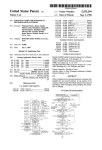
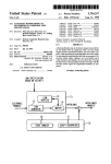
FIG. 2 is a block diagram of the major components of
microphone 32, which may be any suitable microphone
the system of FIG. 1.
such as the headset microphone shown which plugs into
FIG. 3 is a plan view of a typical optional control
the speech recognition unit 30. The voice recognition
sheet for use in the system of FIG. 1.
unit 30 is linked to transmit to the computer 3 control
55
and calculating functions corresponding to vocal com
DETAILED DESCRIPTION OF THE
mands entered at the microphone.
DRAWINGS
The computer 3 is associated with a keyboard unit 10,
In my earlier application, Ser. No. 597,132 now U.S.
a video display unit 11, and a printer unit 12, as seen in
Pat. No. 4,578,768 referred to above, a computer aided
FIGS. 1 and 2. Any suitable computer and peripheral
coordinate digitizing system is described which basi
devices may be used. An interface device 14 interfaces
cally comprises a digitizing device 1 which has been
the computer 3 to the digitizing device 1.
positioned on a flat surface 2 which may be suitable
Suitable computers for use in this system include the
horizontal or elevated surface such as a table, wall,
KAYPRO II, IV, or X or compatible models, or the
inclined drawing board, blackboard or the like, and a
IBM PC, PCXT, PC Junior or other compatible mod
computer 3 associated with the digitizing device. The 65 els.
digitizing device 1 is adapted to measure X-Y positions
Any suitable computer speech input system may be
on a map, plan or other drawing placed on the ?at
used. In the preferred embodiment of the invention, a
surface 2, as described in more detail below.
Pronounce Speech Input System which is produced by
5
4,811,243
Microphonics is used. This system can be trained ac
cording to instructions given in the associated user’s
manual to recognize new words in order to control a
6
positions on plan 13, and entering appropriate com
mands via microphone 32 or sheet 8. When the stylus 5
is placed at a point on the sheet 8 or plan 13, it emits a
chosen application program. Thus suitable programs
sound which is detected by the microphones to enable
them to precisely pinpoint the position touched. A sig
described in my earlier application Ser. No. 597,132,
nal representing the X-Y coordinates of that position is
now US. Pat. No. 4,578,768 and the Speech Input Sys
them entered in the computer’s memory. The computer
tem can be trained to activate a programmed string of
can be programmed to distinguish plan positions from
functions in response to entry of a single word or short
control sheet positions and to operate accordingly, if a
sentence, culminating in a result being displayed on the 10 control sheet is used.
screen 11. A series of different programs may be pro
The control sheet 8 shown in FIG. 3 is provided with
vided for activation by user chosen word commands.
various types of control functions collected together in
The Pronounce Speech Input System consists of a
groups corresponding to programmed computer opera
can be set up for carrying out construction estimates, as
circuit card or board which can be plugged into any
tions. These control functions can also be addressed via
IBM-PC, XT, AT or IBM compatible computer, a mi
crophone which plugs into the circuit card, and a pro
gram which operates the system.
To operate the system, the microphones 6 and 7 and
control sheet 8 (if used) must ?rst be set up on the suit
able ?at surface. The computer 3 may be prepro
grammed to recognize X-Y coordinate data corre
the voice recognition unit 30 so that the unit 30 recog
nizes one or more corresponding vocal commands en
tered at the microphone and converts them into appro
priate computer control signals initiating the desired
operation or sequence of operations. The functions of
FIG. 3 are examples of many possible command or
control functions which may be provided in the system
if desired.
A ?rst group of functions 16 for making conversions
sponding to control areas on the control sheet 9 as the
appropriate control commands, if a control sheet is
used. The program listing for setting up these coordi
from one set of units to another and vice versa may be
nates on a computer will be discussed below. The con 25 provided. In the example embodiment illustrated, these
trol sheet 9 is utilized so that its control areas corre
conversions may include feet to yards, square feet to
spond to the programmed X-Y coordinate positions,
square yards, inches to feet, cubic feet to cubic yards,
pounds to tons, and/or metric measurements.
The second group 17 may provide a listing of various
programs available in the computer for handling data,
for example, such as “Weight,” which is a program for
and it can be used as a control device for operating the
computer by touching the stylus 5 to appropriate con
trol areas on the sheet. Alternatively, the computer and
voice recognition unit are preprogrammed to activate
the same control commands or any keyboard function
in response to entry of one or more vocal commands by
calculating weight of material. Also included in the
preferred embodiment are pitch, area, MBF, topogra
phy, angles, volume, units required. Also included are
computer control function boxes.
A third group 18 may list various mathematical func
tions which can be carried out directly by the operator.
a user, as described in more detail below.
Any desired control functions may be entered by
suitable vocal commands or provided on the control
sheet, or both. The functions are associated with appro
priate instructions in the computer’s memory. Various
A fourth group 19 could provide numerical entry boxes
different control functions may be provided for differ
and YES/NO responses for entering data not available
ent applications of the system. FIG. 3 represents one 40 on the plan, such as numerical scale, depths or thick
suitable control sheet or menu on which a series of
nesses, weight per unit, and so on. The fifth group 20
control areas are provided within boxes 9 printed on the
sheet 8. Each box has one or more commands, entry or
may provide function boxes for carrying out direct
control functions printed on it, and each of these func
sixth group 21 may provide operations functions such as
measurements from a plan, such as length and area. A
tions will be associated in the computer with a corre 45 CE (Clear), RESTART, and PAGE (to record a plan
sponding X-Y position relative to the microphones 6
page number). The operations function COMP. PROG.
and 7.
The menu functions of FIG. 3 or the keyboard 10
activates a compensation program, which allows the
operator to compensate for stretching or shrinking of
paper, or Not to Scale (NTS) drawings. The operator
enters the longest vertical and longest horizontal dimen
sions from the plans. The program will then automati
cally compensate for any future measurements made
may additionally or alternatively be addressed via the
Speech Input System, which is preprogrammed to rec
ognize one or more vocal commands and to initiate one
or a string of computer functions, called MACROS, in
response to chosen vocal commands. The speech input
until the scale is changed by the operator. The SCALE
system and program instructions can be arranged so
that user input of a one word or short sentence com
mand will initiate a string of sequential functions culmi
nating in the display of a result on the screen, in an
equivalent manner to keyboard or control sheet entry of
one or more commands to initiate a programmed se
quence of events.
When the system has been set up with the control
sheet 8 correctly positioned, a plan or other drawing 13
is placed on the surface 2 in the ?eld of the microphones
551
function is used to enter plan scales, according to a key
22 printed on the control sheet.
Some or all of these functions may be provided by
suitable programming of the system, and the system
may provide additional or alternative functions if de
sired, according to the particular application.
The method of making direct measurements using the
system with either the voice recognition unit or the
control sheet shown in FIG. 3 will now be described. It
will be understood that all the commands or functions
6 and 7 or on the electromagnetic or electrostatic board.
described may be entered either via the speech input
The system is then set up to perform any one of a series 65 system, by using the control sheet, or via the keyboard,
of measurements, calculations and other programmed
at the option of the operator. Preferably a switch is
functions at the option of the operator by simply placing
provided for selecting which control option is to be
the stylus 5 or programmable cursor at appropriate
used, and this may be foot operated so that the operator
7
4,811,243
can switch back and forth at will, or by a simple voice
command. Alternatively, the system may be operated
by vocal commands alone, with the keyboard, control
sheet and control sheet position programming instruc
tions omitted partially or entirely. This provides a sim
ple and easy method of operating the system.
8
“ANGLE” is used to determine any angle of a trian
gle, the length of the sides of a triangle, or any area
within a triangle.
“VOL” is used to determine a volume after an area
the corresponding vocal command given. The stylus or
has been measured. For example, if the volume of con
crete in a slab ?oor is to be measured, the area is ?rst
determined using “POINT AREA.” The thickness or
depth of the concrete ?oor is then entered. The resul
tant answer gives the volume of concrete contained in
the floor.
“UNITS REQ’D” determines the total number of
individual units required at a programmed spacing, e.g.
the number of joists required at a selected spacing for a
cursor is then touched to each corner of the design. The
previously measured length of floor, for example.
area enclosed is then computed automatically and the
result given on the view display. To calculate the area
or perimeter of a curved or other odd-shaped design,
the operator gives the command “TRACE AREA” or
“CON. LENGTH” (continuous length) via the micro
phone, keyboard or control sheet, and then traces the
outline of the design. The “POINT LENGTH” is used
to determine straight lengths or the perimeter length of
Suitable programs are provided to determine con
struction cost estimates from stored material costs data
If an operator wishes to ?nd the area of a four cor
nered design on a plan, for example, the plan scale is
?rst entered by touching the stylus 5 or cursor to the
SCALE box and the appropriate numerical boxes, or by
appropriate voice commands at microphone 32. The
measurement box “POINT AREA” is then touched or
a straight cornered structure, and “SEG. LENGTH” is
used to determine the lengths of a series of segments or
lines on a plan, for example lines representing beams,
headers, pipes, and so on. The lengths will be listed
individually, and a total will be computed. “COUNT
UP” and “COUNT DOWN” are used for counting
individual items on a plan, such as electrical outlets. The
FINISH command is used at the end of any measure
ment made. SAVE is used to store measurements in the
computer’s memory.
A series of programs are provided for carrying out
sequential computations from measurements taken from
a plan or map. These programs can be designed for
and parameters calculated from the drawings.
“KEYB’D” allows access to the computer keyboard
unit 10 in order to enter written notations or to change
descriptions of an item to be listed on a print-out, or to
insert program commands in lieu of digitizing or voice
activating them.
“PRINT” is the control commanding the printer unit
12 to print out designated information and calculations.
Clearly other programs or alternative programs may
be provided for speci?c purposes.
A listing of the code for the computer program which
operates a computer to perform the functions described
above is disclosed with application Ser. No. 597,132,
and such disclosure is hereby incorporated herein by
speci?c reference. It is entitled Computer Aided Coor
dinate Digitizing System: DDT VERS 2.2. This pro
gram may also be used in the voice activated control
system.
The initial set-up of the system using a voice acti
vated unit such as the Pronounce Speech Input System
various applications of the system, such as building,
construction, real estate, planning and land use, high
way departments, transportation, military and medical
applications. The programs provided via commands
will now be described. The Pronounce System is ?rst
trained to understand a chosen vocabulary of single or
multiple word commands. Each chosen word command
entered on the menu shown in FIG. 3, the keyboard, or
is ?rst spoken into the microphone, and the de?nition of
via the voice recognition unit may be designed for
building or construction applications, but suitable pro
grams could clearly be provided for the quantity and
cost estimates necessary in other ?elds.
that command is entered on the keyboard, as described
in the Pronounce User’s Manual. After a chosen word
command is entered, the keystrokes which are to be
executed in response to that command are typed in, and
The function of the programs provided in a construc~=
the command may be arranged to initiate one or a se
tion application will now be described brie?y.
quence of computer functions, called MACROS. From
“WEIGHT” is used when a calculation of a total
that point, user entry of that word command will be
weight of material is desired. An appropriate measure
ment function, and the weight per unit is either stored in
the computer memory or entered using the numbered
boxes or the voice recognition unit. A total weight will
then be calculated by the computer.
“PITCH” is used to compute roo?ng areas based on
the slope of the roof and the number of squares of roof
ing required. The total roof area is ?rst calculated using
“POINT AREA”. The roof pitch is then entered. The
equivalent to typing in the selected keystrokes on the
keyboard.
Thus the keystroke “de?nition” or “macro” of a
word command which is entered on the keyboard can
be designed to perform a speci?c function or string of
functions on subsequent entry of that command vocally
in the microphone. In the building estimating system
described above, a user can speak a single word or
sentence in order to activate a string of programmed
numbers of squares of roo?ng required is then reported.
computer functions culminating in the end results, for
“AREA” is used when a dimension not on the plan is
example a total cost or materials estimate, being dis
played on the screen. Once the voice activated system is
needed. For example, if the length of all walls has been
calculated using “POINT LENGTH”, their area can be
calculated by using the “AREA” program and entering
the height of the walls.
“MBF” is used to convert lengths of lumber to mill
board measure, when the lengths have been measured
using “SEG. LENGTH”, “POINT LENGTH” OR
“CON LENGTH.”
“TOPO” is used in land engineering to trace topo
graphical areas, and to compute earth movement.
loaded, or “trained,” according to the speci?c applica
tion program, the program can be run using voice
rather than a keyboard or control sheet. Since a single
spoken command can initiate a whole string of func
tions, the system becomes much faster to operate.
The system can be set up to perform as many multiple
functions automatically in response to a single spoken
command as desired, by suitable entry of keystroke
de?nitions to correspond to the command. Each time
4,811,243
10
that command is spoken, the keystroke de?nition will
The digitizing device and control device can be inter
be entered automatically to control the computer to
perform selected function or functions.
Thus the user can produce multiple vocabularies,
each one referring to a speci?c application or category
of construction such as framing, drywall, concrete
work, site work, and so on. Takeoffs and estimates of
any chosen type can then be run with the appropriate
faced to most computers using a compatible operating
system.
This system is not necessarily designed exclusively
for use in construction Takeoffs and estimates as herein
word command, using the appropriate application pro
described. By modifying the control areas provided
within boxes 9 printed on control sheet 8 utilizing pro
grams indigenous to the user’s requirements, the system
becomes a data input method applicable to Private Avi
gram. Various different application programs can be
provided on separate discs.
ation, Medical Applications, education, transportation,
Marine technology, architecture, engineering, military,
When the user has chosen a command vocabulary,
the Pronounce program is loaded into the computer’s
and others.
It will be clear that modi?cations can be made to the
disclosed embodiment without departing from the
memory, along with the chosen application program.
This system requires the operator only to digitize the 5 scope of the invention. The invention is therefore not
limited to the disclosed embodiment but is de?ned by
quantities from the plan at the appropriate time and to
the appended claims.
initiate a chosen operation or sequence of operations by
a single voice command. This is much simpler than in
previous systems where it was necessary for operators
to perform each function manually in order to accom
plish the desired result.
It is relatively easy and fast to use this system to make
construction cost estimates. A series of construction
drawings representing a structure to be built are laid on 25
the flat surface, appropriate points are digitized and a
sequence of calculations can be made on entry of one or
more simple word commands to provide an estimated
total cost of materials for the structure.
The digitizing system according to this invention is 30
thus quick, convenient and accurate to use. The provi
sion of a voice operated control device which can be
operated by vocal commands of an operator results in
easy and convenient operation of the system, since the
operator does not have to lay down the stylus repeat
edly in order to enter instructions at the computer key
board. This control device may be used alone to operate
the system, but a control sheet may optionally be pro
vided in addition to the voice recognition unit for oper
ation by the digitizing stylus or cursor as described
above. Thus the system may provide three different
control devices, the digitizer control sheet, the key
board and the speech input system. All the necessary
computer control and operating functions may be pro
vided by both the voice recognition unit and the control 45
sheet, so that the operator can decide which control
medium to use, or alternatively certain commands may
I claim:
1. A computer aided coordinate digitizing system for
use in making construction estimates, comprising:
a digitizing device for determining a series of X-Y
coordinate positions on a flat surface, comprising
pointer means for placing at selected positions on
the ?at surface and sensor means for detecting the
position of said pointer means and generating a
series of X-Y coordinate data positions relative to
selected positions on construction drawings placed
on the flat surface corresponding to positioning of
said pointer means at the selected positions;
a computer associated with said digitizing device and
linking means for allowing said computer to re
ceive said coordinate signals, said computer having
memory means for storing program instructions
and said coordinate signals, said program instruc
tions including means for using said X-Y coordi
nate data positions to calculate a series of desired
parameters relative to a structure represented on
said construction drawings for generating an esti
mate of the cost of construction of the structure;
and
user operated control means for operating said sys
tem, comprising voice activated control means for
recognizing voice word commands entered by a
user and generating one or more computer control
signals in response to each voice entered command.
2. The system as claimed in claim 1 wherein said user
operated control means further includes a control sheet
be provided via the voice recognition unit with others
for placing on said flat surface;
entered via the control sheet, or keyboard, for example.
said control sheet having a plurality of control areas
50
When the voice recognition or speech input system
each corresponding to a selected computer func
30 alone is used, the system may be arranged to activate
tion, said computer program instructions further
a string of computer functions automatically on entry of
including means for associating pre-selected X-Y
a single command consisting of one or more words, and
coordinate signals with selected computer func
to display the result automatically. The user can set up
the system to perform as many multiple functions as
they desire automatically. This is much easier than en—
tering each speci?c command function manually. The
voice commands automatically address the basic menu
tions, and means for positioning said control sheet
such that each of said control areas coincides with
a respective one of said pre-selected X-Y coordi
nate positions.
3. The system as claimed in claim 2, wherein said user
functions provided above and automatically input the 60 operated control means further includes a keyboard
functions to the computer at the appropriate time. All
the operator has to do is initiate the operation by the
appropriate vocal command and to digitize the appro
priate quantities at a suitable time using the stylus or
associated with said computer and switch means for
selectively controlling said computer via said voice
recognition means, keyboard or said control sheet.
4. The system as claimed in claim 1, wherein said
programmable cursor. The cursor may be provided 65 voice recognition means includes means for recognition
with keys and may be pre-programmed to allow some
of vocal commands corresponding to numerical entry,
commands to be entered at the cursor rather than via
computer operating functions, and activation of pro
the control sheet, keyboard or voice input unit.
gram instructions stored in said computer.
11
4,811,243
12
prising a series of construction drawings, comprising
the steps of:
placing a series of construction drawings representing
5. The system as claimed in claim 1, wherein said
voice recognition means includes means for recognizing
a predetermined vocal command corresponding to a
preselected sequence of control functions and for con
a building plan sequentially on a ?at surface.
positioning a pointer device at a series of selected
verting said vocal command into the corresponding
computer control signal for initiating each control func
tion, said computer program instructions including
positions on each drawing;
monitoring the pointer device with a sensing device
linked to a computer;
means for performing the preselected sequence of func
tions in response to the respective control signal.
6. The system as claimed in claim 5, wherein said
control functions comprise means for generating an
controlling the sensing device to generate a series of
estimate of the total cost of a building represented or a
X-Y coordinate signals corresponding to the posi
tioning of the pointer device on the drawing;
providing the generated series of X-Y coordinate
signals as data input to the computer; and
plan.
controlling the computer by means of a voice recog
7. The system as claimed in claim 1, wherein said
pointer means comprises a programmable cursor for
moving over said surface, said cursor having cross hairs
for centering at chosen cursor positions on said surface
and means for generating a signal for detection by said 20
sensor means.
8. A method of generating an estimate of the cost of
construction of a building represented by a plan com
nition device to respond to entry of at least one
vocal command into the device to utilize the data
input from the sensor device and program instruc
tions stored in the memory of the computer to
calculate a series of desired parameters and to gen~
erate from the calculated parameters an estimate of
the cost of construction of a building represented
by the construction drawings.
‘I
25
30
35
45
50
55
65
i
i
*
i