1
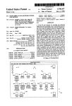
US005341305A
United States Patent [19]
Clarino et a1.
[11]
[45]
[54]
4,963,703 10/1990 Phillips et a1. .
A COMPUTERIZED PATI‘ERN
DEVELOPMENT SYSTEM CAPABLE OF
DIRECT DESIGNER INPUT
Patent Number:
Date of Patent:
5,089,971
2/ 1992
5,341,305
Aug. 23, 1994
Gerber ................ ..
.. 364/470
5,172,326 12/ 1992 Campbell, Jr. et a1
.. 364/470
5,175,806 12/ 1992 Muskovitz et al. ............... .. 395/ 125
[75]
Inventors: Thomas N. Clarino, East Haven;
FOREIGN PATENT DOCUMENTS
Mary M. Altshul, South Windsor,
both of Conn.
[73] Assignee: Gerber Garment Technology, Inc.,
Tolland, Conn.
[21] Appl. No.: 694,666
May 2, 1991
[22] Filed:
Int.
01.5
............................................
.. G06F 15/46
[51]
[52] Us. (:1. .................................. .. 364/470; 364/468;
364/474.24
[5 8]
Field of Search ............. .. 364/470, 468, 469, 471,
364/474.24; 395/125
[56]
References Cited
U.S. PATENT DOCUMENTS
3,391,392
3,473,157
3,534,396
3,596,068
3,766,528
3,81 1,113
3,887,903
3,895,355
3,924,244
4,058,849
4,149,246
4,451,895
4,539,585
4,546,434
4,552,991
4,570,033
4,578,376
4,807,143
4,853,715
4,961,149
7/1968
10/1969
10/1970
7/1971
10/1973
5/1974
6/1975
7/1975
12/1975
11/1977
4/1979
5/1984
9/1985
10/1985
1l/1985
2/1986
7/1986
2/1989
8/1989
10/1990
Doyle .
4013836 10/1991 Fed. Rep. of Germany .
4100534 1/ 1992 Fed. Rep. of Germany .
85634A/89 ofOOOO Italy .
1221349 ofOOOO Italy .
2050658 of 0000 United Kingdom .
OTHER PUBLICATIONS
Lisa Cedrone, CAD/CAM Marches On, pp. 82-86,
Bobbin, Jan. 1991.
AccuMark 300 User’s Manual, Document No.
05231-003, Issue No. 3, Apr. 1989, Chapter 6, by Ger
bar Garment Technology, Inc.
Primary Examiner-Jerry Smith
Assistant Examiner--Jim Trammell
Attorney, Agent, or Firm--McCormick, Paulding &
Huber
Little et a1. .
Hart et a1. .
[57]
Doyle .
ABSTRACT
Ichida .
A pattern development system for use during the gar
Saito et al. .
ment development process includes a digitizer with a
Martell .
work surface. The designer draws the lines of the gar
Shorrock .
ment pattern on the work surface with a stylus that
Seitz .
enables the digitizer to present position signals to a
Fitzgerald et al. .
Goldman .
controller in real time. The controller includes algo
Sliwkowski .
rithms to compose the drawn lines into a garment pat
Spackova et al. .
tern as well as compensate for human errors such as
multiply drawn lines and missing line portions. The
present system is transparent to the designer in opera
Gioello .
Hulls .
Hulls .
Burton et al. .
Matsuura .......................... .. 364/470
tion as it adapts to the human designer rather than forc
ing the designer to adapt to the system.
Paschkis .
Schneider et a1. ................ .. 364/410
62
26 Claims, 5 Drawing Sheets
US. Patent .
Aug. 23, 1994
Sheet 1 of5
5,341,305
T5 5/ A
\. I ‘b6 J /
§¥
'
22
‘
ZZNQ
FIG. I
PRIOR ART
[74
76‘\
‘
/.J86
(78
"\-84
83’
FIG. 7
>
;
8O’
US. Patent
Aug. 23, 1994
Sheet 2 of 5
5,341,305
FIG. 2
PFBIIQR ART
26
24
US. Patent
‘Aug. 23, 1994
Sheet 3 of 5
5,341,305
34
Z
30
FIG. 3
PRIOR ART
4244
FIG. 4
PRIOR ART
33]
US. Patent
Aug. 23, 1994
Sheet 4 of 5
LO
92
u.
54
62
52
5,341,305
US. Patent
Aug. 23, 1994
5,341,305
Sheet 5 of 5
INITIATE SYSTEM
SELECT
OUICKDRAW
OPTION
IDENTIFY SYSTEM
CONFIGURATION
72L
I DENTIFY
QUICKDRAW
VERSION
SELECT MENU LOCATION
ON DIGITIZER
,90
CHOOSE FUNCTION
92
SKETCH
94
IIAjITEiIIcIEJ
I RACE DRAFTI
IOO
I02
ZJCE
FIG. 6
ICURVEI
I04
ISCRIBEI
106
98
IREJECTI
I08
no
I PLOTI
REORIENT
(88
CHOOSE GARMENT PATTERN
SIGNAL 6 ROUP
1
5,341,305
2
matching relationships. A vision sensor is then automat
A COMPUTERIZED PA'ITERN DEVELOPMENT
SYSTEM CAPABLE OF DIRECI‘ DESIGNER
INPUT
ically positioned over the spread pattern fabric which is
to be cut in the positions of the matching points which
have been de?ned for each one of the panels which
have been distributed for cutting. The relative design
position with respect to a reference position at each of
the matching point positions is then determined and a
position correction obtained for each panel with respect
to the position initially assigned to each one of the pan
TECHNICAL FIELD
The present invention relates generally to systems for
use with the design of fabric articles and more particu
larly to computerized systems for use in the design and
10 els to be cut. Each position correction is obtained on the
creation of garments.
basis of the positions of the pattern determined in the
CROSS-REFERENCE TO RELATED
previous step and on the basis of the previously de?ned
APPLICATIONS
matching relationships wherein all of the panels which
Some of the subject matter hereof is disclosed and
are to be cut are matched prior to proceeding with their
claimed in the commonly owned US. patent applica
cutting operation.
tions entitled “A Garment Cutting System Having
Computer Assisted Pattern Alignment”, Ser. No.
694,871; “Method For Splitting Marker Lines And
Related Method For Bite-By-Bite Cutting Of Sheet
Material”, Ser. No. 694,942, U.S. Pat. No. 5,214,590
each of which is incorporated herein by reference.
US. Pat. No. 4,149,246 discloses a system for creat
ing custom garments of clothing by combining data on
a personal tailoring measurements of the wearer, physi
cal characteristics of the wearer, garment pattern and
20
garment options selected on the basis of resulting com
binations of personal pattern data. The ’246 system is
BACKGROUND OF THE INVENTION
embodied with a central location unit including a cut
ting table apparatus, a memory and a pattern processing
Computerized systems adaptable for use with the
system. The central units serves a plurality of remote
fabrication of clothing are known in the art. Known 25 location equipments through a communication system.
systems include US. Pat. No. 4,546,434. The method
The remote equipments include an interactive graphic
disclosed in the ’434 patent is for visually composing
display wherein an operator can customize the garment.
and editing original apparel designs and includes the
A garment pattern is ?rst selected from memory. Per
steps of providing a plurality of con?gurations of indi
sonal physical data is supplied and the two forms of data
vidual garment components, compiling a computer 30 are combined to provide a representative of the combi
database from which the components may be retrieved
nation. Upon con?rmation, the speci?c pattern data is
and assembled in a ?nished apparel format on a ?gure
processed
to control a central location cutting table
outline in selected composite fashion, and if desired,
apparatus to provide the components which are sewn
modifying the apparel design by replacement of any
component by a selection of a new element from the 35 together to create the desired garment.
US. Pat. No. 4,058,849 discloses a system for con
database by the use of an electronic locating instrument.
verting
a rough sketch into a ?nished drawing. In the
Further, the design may be presented as a permutation
’849 system, an electronic digitizing tablet or its equiva
of any one or more selected parts. When a design is
lent is used to receive a roughly sketched object by an
completed, its component CRT image is made available
in accordance with the ’434 method as hard copy which 40 operator along with the desired ?nal proportions which
can subsequently be used in cutting component parts
comprising the design on suitable piece goods.
US. Pat. No. 3,596,068 discloses a system for opti
mizing material utilization. ‘The ’O68 system automati
cally arranges patterns on a surface of a material in a 45
manner which will require less material than which
would otherwise be consumed by a human performing
the same task. The simulated movement of each pattern
piece about an established marker boundary is accom
are entered into a stored table called a pointing se
quence list (PSL) capable of storing all of the informa
tion required to de?ne both the original form and the
desired ?nal con?guration of the object. The PSL ini
tially contains positional entries representing the coor
dinates of de?nitive points on the roughly sketched
object and dimensional entries specifying the propor
tions which the object is to have in its ?nal con?gura
tion. These are arranged in an order corresponding to a
plished by data processing techniques. Once the con
prede?ned pointing sequence which is followed by the
tour of a piece outline and boundary outline is known
and the slopes of the vertex connecting the segments are
graphic information system. The PSL is subsequently
operator when he enters the necessary items into the
converted to a new PSL by a rectifying procedure
determined, the ’O68 system displaces the pieces within
which modi?es the coordinates of the previously en
the boundary in a nonoverlapping manner.
US. Pat. No. 4,853,866 discloses a method and appa 55 tered points when necessary in order to effect the hori
ratus for matching panels to be cut from pattern fabrics. ' zontal and vertical alignments of points ostensibly lo
cated on common, axially directed lines. Consequently,
The ’866 method and apparatus ?rst de?nes matching
the ’849 system is limited to rectifying a rough sketch
points in each of several patterns of panels to be cut and
into a preferred ?nal geometry to eliminate undesirable
digitizes the panels at these points so that the coordi
irregularities from, for example, nonparallel lines.
nates in respected identi?cation codes for each of the
points are recorded in memory. Matching relationships
are then de?ned for the matching points which unequiv
ocally ?x the position which the design must be in at
each of the matching points and records these relation
In addition, the prior art includes systems for manipu
lating databases which have digital images of articles,
such as garment segments, (equivalently; pieces, panels
or patterns). However, the prior art is directed towards
ships in memory. Thereafter, separation margins be 65 the creation and manipulation of computer databases
tween the panels and distribution are established by the
’866 method and apparatus, either automatically or
interactively on the basis of the previously de?ned
after the garment segments have been put in their ?nal
form for that garment piece by the designer or pattern
maker. The known systems are all characterized by
3
5,341,305
computer software which requires closed polygonal
BRIEF DESCRIPTION OF THE FIGURES
FIG. 1 is a plan view of a drawing having key body
elements in order to be manipulated, such as for grading
or other purposes. Further, the natural intuitive actions
of the designer during the development process, such as
erasures, redrawn lines, etc., are not compatible with
landmarks and sketches of garment piece patterns.
FIG. 2 is a plan view of a drawing from which gar
ment piece patterns are lifted.
FIG. 3 is a plan view of a drawing board having
the known computerized systems.
It would be advantageous to have a system which to
garment piece patterns affixed thereto.
be used to during the creative pattern developing pro
cess itself that digitizes an article’s elements in real time
FIG. 4 is a simpli?ed illustration of a digitizing tablet
used with a prior art digitizing system.
FIG. 5 is a simpli?ed schematic illustration of a pat
This system would be capable of use during the devel
tern development system provided according to the
opment process in which the garment segments have no
present invention.
preselected ?nal geometric shape. The present inven
FIG. 6 is a diagram showing an algorithm executed
tion is drawn towards such a system.
15 by the controller of FIG. 5.
SUMMARY OF INVENTION
FIG. 7 is a schematic illustration of a digitizer used
with the system of FIG. 5.
An object of the present invention is to provide a
pattern development system for use during the garment
DESCRIPTION OF THE PREFERRED
design and pattern making processes capable of creating
EMBODIMENT
a database of signals corresponding to drawn garment
A
pattern
maker
or designer of a garment begins the
segment patterns.
development
process
by drafting a garment pattern
Another object of the present invention is to provide
from
(1)
scratch,
(2)
a
?rst pattern, (3) a production
a pattern development system of the foregoing type
pattern from a previous style, (4) a pattern from an
and constructs the garment segments in a ?nal form.
capable of real time generation of position signals for
the database as a garment segment pattern is being
drawn.
Still another object of the present invention is to
provide a pattern development system of the foregoing
type that composes digitized signals representing drawn
25
existing garment or (5) by working from fabric which
has been draped on a dress form or ?t model. Each
garment pattern is comprised of a plurality of garment
pattern segments or pieces.
Referring now to FIG. 1, there is shown a drafting
table 10 on which is a large sheet of paper 12. When
pattern lines into pattern signal groups corresponding to
drafting a pattern from scratch, the pattern maker be
drawn garment segments.
gins with the blank piece of paper. Initial guidelines 14
Another object'of the present invention is to provide
representing key body landmarks are drawn in pencil on
a pattern development system of the foregoing type that
the paper with the aid of straight edges (rulers). Lines
edits said pattern signal groups by deletion or addition 35 16 representing the garment piece 18 (garment pattern
of position signals to provide a complete pattern, free of
segment) are then created off of the guidelines using
extraneous position signals.
rulers, curve templates or by drawing curves freehand.
According to the present invention, a system for use
Initial changes are made by the pattern maker by simply
in developing a garment pattern comprised of a plural
erasing unwanted lines such as line 20. Also, the pattern
ity of garment pattern segments includes a stylus for 40 maker may wish to darken an ink line of the garment
drawing a visible line on a sheet of work material and
further having an enabling mechanism for selectively
enabling the generation of position signals in an electri
cal circuit in proximity with a stylus tip. A digitizer
having a digitizing panel in substantial registration with
a work supporting surface is adapted to receive the
work material sheet. The digitizing panel has an electri
cal circuit for producing position signals representing
the position of the stylus tip relative to the supporting
surface as the stylus is moved over the work supporting
surface in proximity thereto. A controller is adapted to
receive the position signals and to generate a database of
signals corresponding to at least one garment pattern
piece as an aid during the development process. This is
typically done by retracing one or more of the lines 22
in the garment piece.
When working from a ?rst garment pattern segment
45 which is created to capture the intent of the designer,
changes must be made which make that style of gar
ment production ready. As shown in FIG. 2, each piece
is separately lifted off in the prior art by tracing and
cutting the individual garment pattern segments 24, 26
from a separate sheet (or sheets) of paper 28, 29.
Manufacturing standards must be then integrated into
the pattern pieces 24, 26. Therefore, the patterns must
be again altered. Typical changes include checking for
segment. The controller includes a composing mecha 55 curve shapes, angles, generation of facing/secondary
pieces, standard seam allowance treatments, measure
nism for ‘composing pattern segment lines from a set of
adjacent position signals and further forming garment
ment checks (both across pieces and perimeter lines),
and necessary markings for notions. The pattern maker
will first examine the existing pieces for the style to
pattern segment signal groups from selected ones of said
pattern segment lines corresponding to said garment
determine the changes which need to be made. The
pattern segment. An editor is provided for editing se
pattern segments are taped to the pattern makers table
lected position signals in said segment lines in response
and again traced onto a clean piece of paper that is laid
to instruction signals. A memory stores the signal data
over the original. The subsequent tracing is subse
base. Also, a graphic display device connected with the
quently altered to re?ect the desired changes. Markings
controller visually displays selected ones of the position
can also be transferred using a known tracing wheel.
signals as well as the instruction signals and signals 65 Adjustments are then made according to the pattern
indicative of the operational status of the system. An
maker’s judgement.
input mechanism provides for the manual input of the
It is common to use the patterns of styles from previ
instruction signals to the controller.
ous seasons which are similar to the intended design. In
5
5,341,305
this way fewer changes are necessary and less time is
needed to create the new patterns. In a manual produc
tion environment such piece patterns 30 are in a hard
paper (manila) or plastic form. As demonstrated in FIG.
3, the pattern maker tapes or pins a blank piece of paper
32 to the table 33 and places the hard pattern on top.
6
design relies on human perception of subtleties such as
texture and proportion in three dimensions, all of which
are lost in a computer graphics display.
In contrast, the present invention solves the problems
of the prior art by adapting the computer system to the
The pattern can be traced by simply running the pen
cil/pen against the edge of the pattern. Internal mark
existing development process and endeavors to be as
transparent to the designer as possible. Referring now
to FIG. 5, there is schematically shown a pattern devel
ings can be obtained by sticking a push pin 34 through
the manila pattern along the internal markings. A line
opment system 46 provided according to the present
(dashed line 36) is then created on the traced pattern by
invention. The system 46 can be used as a stand alone
unit or as a supplement to an existing garment piece
connecting the pin pricks on the tracing paper using
database manipulation system. The system 46 comprises
rulers and/or curves. Internal markings can also be
a large drafting table 48 which is also con?gured to be
transferred to the tracing paper by placing the manila
pattern underneath the tracing paper and the internal
a digitizer. The size of the table 48 is selected in accor
markings are traced off of that.
Patterns can also be taken from existing garments in
large enough to accommodate garment piece patterns
or the garments themselves (e.g. input surface
the prior art by disassembling the garment into cloth
pieces, placing the cloth piece onto the table and then
transferring the cloth piece shape to paper by typical
dance with the wishes of the designer, but is typically
66"><48", 44"><36” through 12"><l2"). The drafting
methods such as tracing or using a pattern wheel. De
signing can be done directly on a dress form or ?t model
table/digitizer can be of the type sold by the Numonics
Corp. of Montgomeryville, Pa. and may have a back
light, if desired. A stylus 50 is included and is character
ized by a point 52 which will write in ink or pencil on
by draping the fabric thereon. The fabric can be pinned
a paper sheet 54 placed on a top surface 56 of the table.
in place, drawn on and cut or clipped with scissors. The
The stylus is preferably of the cordless and graphite
result can be used as a guide to create a paper pattern. 25 type, and further comprises a manually selectable
The fabric is laid ?at on the table and the shape and
switch which enables signals to be presented to receiv
markings are transferred to paper in the manner de
ing elements in the table in a known manner to digitize
scribed above.
the position of the stylus as it is moved about the top
Multiple pieces or garment segments are required to
work surface.
make a single garment. It is often necessary to create 30 The present system further comprises a controller 58
certain curves (areas) by reworking common areas on
programmed in accordance with algorithms detailed
corresponding pieces with multiple iterations where the
hereinafter to convert the lines drawn into piece pat
requirements of the geometry on the paired pieces is
terns for subsequent manipulation in a garment database
dependent on the remaining pieces of the garment. This
such as is done with the aforementioned GGT Ac
must be done on the paper patterns.
35 cumark system. The controller preferably comprises a
Once the development process is ?nished, the gar
80386/486 type 32 bit processor, a 32 bit mathematics
ment piece patterns can be digitized by known systems,
coprocessor, 4 Mbytes of internal memory and 40
such as the Accumark system marketed by Gerber Gar
Mbytes of storage. A 1.2 Mbyte diskette is provided as
ment Technology (GGT), the assignee of the present
well, as is other conventional components need to con
invention. As seen in FIG. 4, with the Accumark system 40 ?gure the controller to operate with a MS-DOS operat
a predrawn and/or cut garment piece pattern 38 is
ing system such as a keyboard and printer. Also in
taped or pinned onto a digitizing tablet 40. Digitizing
cluded is a monochromatic system management work
puck 42 is manually moved about the tablet along the
station 60 and a color design and marking workstation
perimeter of the pattern. Selected points therealong are
62 used during the development process. The present
picked off by activation of appropriate switches 44 on 45 system will support the operation of a plotter or cutter
the puck. The Accumark system is con?gured to create
64 as well. The table and stylus receiver unit (not
a digital image of the predesigned garment piece pattern
shown) plug into a “mouse” port on the controller for
and store that image in a garment piece pattern database
receiving data in serial format.
along with other images of garment piece patterns for
The development process provided by the present
similar pieces, such as sleeves. These stored images can 50 invention can begin in a number of ways, such as by
be manipulated by a computer to compose a garment of
taping or pinning paper patterns or fabric to the design
selected images as well as grade these images for differ
surface. Fresh paper is then overlaid and taped or
ent sizes.
While the adoption of computer based systems in the
pinned on the pieces. When drafting from scratch, only
clean paper is placed on the design surface. The initial
development process in many areas such as architecture 55 pattern is then traced onto the clean paper using the
or engineering has proceeded quickly, the same cannot
systems pen/pencil-stylus. As the lines are traced using
be said for the clothing industry. At present, there re
rulers and curves, the stylus transfers the markings to
mains a strict bifurcation of the process of making gar
the paper and computer screen simultaneously. To trace
ments into the “creative”, initial phases accomplished
the pattern lines, the pattern maker as user can trace the
without computerization and the subsequent ones that 60 lines in multiple subsegments adjusting and switching
adapt designs for mass production in which computers
tools, in nonconsecutive order and in different direc
are used routinely.
tions. All in contrast to known systems which require
The great resistance to computerization by designers
lies with the failure of known systems to adapt to the
human development design process. Instead, designers
consecutive movement in a single direction.
As illustrated in FIG. 6, the present system is ?rst
65 initialized at block 66. When con?gured with an Ac
were expected to adapt to the computer systems and
cumark system, the present pattern development system
design clothes on, for example, video display terminals.
It has not been appreciated by the prior art that garment
is executed from the AccuShell main operating pro
gram menu by executing the “Silhouette” labeled op
7
5,341,305
8
tion (block 68). The submenu options of “Silhoutte”
system is con?gured to be used with a “stylus” of a
include RUN SILHOUTTE, RUN SYSTEM
MANAGMENT and RETURN TO MAIN MENU.
Selecting RUN SILHOUETTE will initiate the pro
gram, displaying the “color-scope-idle” screen which
has SILHOUETTE in place of the MED and PDS
algorithm options that are otherwise found with the
Accumark system. Selecting RETURN TO MAIN
known type having a depressable barrel switch therein.
As seen in FIG. 7, the subportions 78, 80 comprise
three areas 83, 84 and 85. Lower area 83 is used to input
commands from the surface and contains menu options.
A list of the different garment pieces is found in area 85.
The relative size of the areas 83 and 85 are exaggerated
for illustrative purposes. In order to decrease user arm
menu. Selecting exit from within Accumark digiting
movement while selecting from the menu area or the
icon menu and to allow the user to work in a reduced
program “pattern development system” (PDS) returns
input area, area 84, 6" X 6" in dimension is also mapped
the user to the AccuShell. Selecting RUN SYSTEM
to the entire work area of the screen. When the user has
not selected a command function and moves the stylus
MENU returns the user to the ACCUSHELL main
MANAGEMENT executes the System Management
from the primary input area 86 of the work surface to
data management processes such as reports, editors, 15 the section 78 or 80, the algorithm alters the scale of
movement of the cursor on the display. If, however, the
piece verify and order. Selecting SHUTDOWN returns
user is in a command function mode and moves the
the user to the SYSTEM MANAGEMENT submenu,
stylus in the area 83, there is no effect on the system, and
and selecting EXIT from the submenu returns the user
algorithm from which the user can access the standard
to the ACCUSHELL main menu.
the user can operate the system within that area without
questions are asked with the corresponding options
indicated:
for that particular iteration. Regardless of the tech
nique, the present invention digitizes the pattern lines to
comprise a sequence of position signals presented di
rectly to the controller.
When the present invention is ?rst installed or con?g 20 the digitized input signals changing scale.
Lines can be created in several different ways while
ured, additional questions to the user are posed at the
designing
with the present invention. Curves can be
initiation of the SILHOUETTE algorithm, including
created by the user depressing the stylus tip and drag
those designed to determine the hardware con?guration
ging the stylus as the curve is being drawn. A curve
of the system (block 70) and the version of the algo
rithm (block 72). After the system asks, “IS THIS A 25 template or straight edge can be employed or the lines
drawn freehand. While tracing an existing pattern, all of
PLOTTER WORKSTATION?”, the system will
the straight line segments can be created ?rst using a
prompt “IS THIS A SILHOUETTE WORKSTA
straight edge or ruler, and then drawing all of the curve
TION”. If the user answers in the negative, the algo
lines. An alternate approach would be to work in one
rithm continues without asking the questions relevant to
SILHOUETTE. If the user answers yes, the following 30 area of a garment pattern segment until it is completed
WHICH CONFIGURATION OF SILHOUETTE DO
YOU HAVE?
‘
l. SILHOUTI'E ADD ON TO STANDARD ACCUMARK
2. SINGLE SCOPE SILHOUTTE STATION
WHICH SIZE INPUT TABLE DO YOU HAVE?
L 60,, X 44”
2. 40" X 36”
As noted above, the present invention as set forth in the
SILHOUETTE embodiment can be added to existing
Accumark systems or integrated into a single system.
The input table refers to the digitizer with the planar
35
The user must select which function is to be imple
mented by the system (block 90). Before the lines are
sketched, the user selects the garment pattern signal
group for a garment pattern to which the new pattern
lines will belong (block 88). The function choices are
sketch (block 92), trace draft (block 94), create piece
(block 96) curve/line (block 98), scribe (block 100), trim
(block 102), reject (block 104), draft scale and draft
zoom (block 106), plot (block 108) and reorient (block
110). The operation of the various functions are detailed
hereinafter.
In response to the prompt SKETCH FUNCTION,
work surface. The present invention also includes an
SELECT BLOCK (GROUP) TO SKETCH LINE(S)
option for a stand up plotter that is added to a plotter
the user begins drawing lines. As the lines are drawn on
con?guration prompt presented to the user at this time.
the paper they appear on the display screen. PRESS
Except for a small section of the tablet, the entire 50 STYLUS TIP AND DRAW TO SKETCH LINES. If
input surface of the table is mapped to the entire work
this function is used to create only perimeter lines of a
area of the PDS screen in a full-scale mode. In FIG. 7
garment pattern, then DRAFT/CREATE PIECE is
there is shown a tabular digitizer 74 having a work
used to create a garment pattern segment for the PDS
surface 76. Subportions 78 and 80 correspond to those
function in the Accumark system. If this function is used
portions of the work surface which are not directly 55 to draft a piece, or trace internals as well as perimeters,
mapped into the garment pattern segment database as
then DRAFT/TRACE DRAFT function is used to
detailed hereinafter. These subportions are con?gured
create a PDS piece. The controller automatically as
to enable the user to select program options with the
sembles the position signals into the various segment
stylus directly without the use of a keyboard or mouse.
lines and identi?es them as associated with a particular
The command MENU LOCATION allows the user to 60 signal group.
position this area in either the bottom left or bottom
When the position signals that correspond to the
right subportions of the surface. The default setting is
pattern lines are compiled into the selected block or
for the right side. Selecting this option will toggle the
group, the present system is con?gured to automatically
menu position. The following is presented to the user:
correct and compensate for the variations in the perime
MENU SELECTION AREA IS LOCATED ON 65 ter caused by subsequent traces of the pen. Therefore,
THE RIGHT (LEFT) SIDE OF THE TABLE,
when a designer “darkens” a pattern line by multiple
PRESS STYLUS BARREL SWITCH TO CON
passes of the pen, the present system disregards subse
TINUE. See block 82, FIG. 6. Note that the present
quently generated position signals if they are identical
5,341,305
10
to the previously generated ones and computes an “av
selected is labeled as the primary grain line, GO, and the
erage” pattern line for those that are displaced laterally
from the initially drawn pattern line. In this regard, the
present system determines a position of the desired
others are labeled and numbered in order of selection.
pattern line based on an average position of the sepa
grain line to be generated automatically.
Depressing the barrel switch button without selecting a
line when replying to this prompt causes a horizontal
rately drawn sublines.
Further, the present system determines which posi
The RESKETCH function is used to enter lines into
the perimeter of a “legal” or system compatible piece,
to replace existing lines. SELECT LINE(S) TO RE
tion signals are extraneous in that they are located be
yond the perimeter of the garment pattern. In those
stylus fully about the perimeter, the present system
PLACE is the command used with this function. The
selected lines are shown on the display in red. In re
sponse to the PRESS STYLUS TIP AND DRAW TO
SKETCH LINES, DEPRESS BARREL SWITCH
situations where the drawn lines are incomplete be
cause, for example, the designer failed to move the
determines an appropriate intersection with an adjacent
TO END prompt, the user draws the new lines which
pattern line and generates the corresponding position
signals to complete the garment pattern segment signal
display as they are created. After the barrel switch is
depressed the new pattern lines are entered into the
group. The ability of the present system to work with
the pattern lines as drawn when compiling a garment
piece perimeter and the original lines are replaced.
If, after the pattern segments are sketched, the lines
pattern segment signal group marks an important point
of departure of the present invention over the prior art.
extend too far past or do not meet at an intersection, the
system may not be able to ?nd the proper intersection
The function CURVE is used to enter curved pattern 20 created by two adjacent lines. Therefore, after a pattern
lines by entering points along the curve in the manner of
digitizing rather than sketching the lines. This feature is
segment has been sketched and the function CREATE
PIECE is used unsuccessfully as indicated by the com
also possible for straight lines too, like digitizing. The
ment “LINE ORDER FAILURE” the intersect func
system then creates a curved line of position points in
tion is used to trim the intersections of two lines. With
25 the intersect function, the user selects a point and moves
the database which encompasses the entered points.
Initially, the user selects the signal group desired in
it along the direction of the line which it is on in reply
response to the prompt Step 2 SELECT BLOCK TO
to SELECT POINT TO REPOSITION, DEPRESS
CREATE CURVE. Next, the user selects the signal
BARREL SWITCH TO END. The points are then
points in the curve in response to Step 2 SELECT
placed close to the proper intersection.
The REJECT function is used to reject lines created
POINTS ALONG CURVE, DEPRESS BARREL
SWITCH FOR STRAIGHT LINES. Beginning at one
during the SKETCH function. While in the SKETCH
end of the curve, points are created by depressing the
function the user can select the REJECT which deletes
stylus tip at intervals along the curve. As the points are
the last line created. No prompt is given.
placed they are displayed on the screen. Signal points
The REORIENT function is used to orient the pat
can be deleted in the same way as in the LINES/DI 35 tern segment displayed on the screen to the orientation
GITIZE LINE function.
of the piece on the table. This function lets the user pick
The CREATE PIECE function creates an accept
up the paper or fabric pattern and reposition it on the
able AccuMark piece (garment pattern signal group as
table while working and have the garment pattern on
designated in the present application), a closed ?gure
the screen display in the same orientation so that
with lines received in order in the clockwise direction.
sketched lines can continue to be input. This function
This function is only used for sketched pieces which
can be used to enter large pattern segments by ?rst
have no internal structure. Those garment patterns that
sketching in a portion, repositioning the pattern seg
have such internal structure have to be created after the
ment on the table, using REORIENT and then sketch
perimeter is closed unless TRACE DRAFT is used in
ing in the remainder.
the drawing process. Initially, the system provides the
prompt: SELECT BLOCK(S) TO CREATE, DE
PRESS BARREL SWITCH TO END. The user se
lects the block(s) representing the garment pattern to
create and then illustrates the position signals on the
display in red. After the barrel switch button is de
pressed,'the garment pattern signal group is created and
displayed with stripe line and symbols. The default
45
To use the REORIENT function, the user selects
two points on the piece displayed on the screen to be
re-displayed in a new orientation when presented with
the prompt SELECT TWO POINTS ON PIECE DIS
PLAYED ON SCREEN. In response to SELECT
CORRESPONDING POINTS ON PIECE ON TA
BLE, the corresponding points are selected on the
paper pattern on the table by depressing the stylus tip.
orientation is horizontal.
The garment segment displayed on the screen is then
The TRACE DRAFT function is used to de?ne the
redrawn to re?ect the correct orientation. The system
perimeter lines of a garment pattern segments, the inter 55 will perceive an error should two sets of points not same
nal lines of a draft are then selected. With the command
distance apart. The user must then re-input the selected
points.
SELECT PERIMETER LINES, DEPRESS BAR
Completed garment pattern segments which are
REL SWITCH TO END, the pattern lines are selected
in order in a clockwise direction. As the pattern lines
newly created and not stored in the AccuMark Data
that correspond to the perimeter of the garment seg
base can be plotted on a standup plotter directly from
ment pattern are selected they are displayed in red.
PDS. The garment pattern segment perimeter and inter
Pattern lines can be selected as in the standard CRE
nal structural lines are plotted with solid and dashed
ATE TRACE function. The intemal lines are selected
lines. The user sends the data to the plotter (e.g., Ioline
and display in red in response to the prompt SELECT
or Numonics brand plotter). The plot is entered into the
INTERNAL LINES, DEPRESS BARREL SWITCH 65 plotter queue and then sent to the plotter. A single
plotter can be used between two systems by means of a
TO END. SELECT GRAIN LINES, DEPRESS
BARREL SWITCH TO END is the prompt for select
switch. The system will typically check to see if the
ing the lines to be kept as grain lines. The ?rst one
plotter is connected, but not in all con?gurations. It is
11
5,341,305
desirable that the plotter have a small footprint but
12
internals can be scribed. When internals are scribed
thereto may be made therein without departing from
the spirit and scope of the present invention.
We claim:
1. A system for use in developing a garment pattern
that includes a plurality of preferred garment pattern
segment lines positioned in a spatial sequence with con
secutive ones of said pattern segment lines having an
intersection corresponding to the ends thereof, said
1/16” is left on the end of the line indicated by the user.
system comprising:
simultaneously be able to accommodate large drawings.
In this regard, “roller” type plotters are preferable to
?atbed ones.
Garment pattern segments which are not stored in the
AccuMark Database can be scribed or cut on the plotter
using the scribe option. Both the perimeter and selected
The garment pattern segment is entered into the plotter
queue before presentation to the plotter. The plotter
a stylus having a means for drawing a visible line on
a sheet of work material and further having an
uses the blade option rather than the pen to scribe the
enabling means for selectively enabling the genera
tion of position signals in an electrical circuit in
piece. SELECT BLOCK TO SCRIBE initiates the
function. The user selects the block or garment pattern
signal group, and the system prompts SELECT IN 15
TERNALS TO SCRIBE, DEPRESS BARREL
SWITCH TO END.
The user selects the internal pattern line (internals) to
proximity with a stylus tip;
a digitizer having a digitizing panel in substantial
registration with a work supporting surface
adapted to receive said work material sheet, said
digitizing panel having an electrical circuit for
be scribed. The blade is moved as with a pen, scribing
through the chosen media on the plotter. In some con 20
tion of said stylus tip relative to said supporting
?gurations the system will program the plotter to lift
the blade in tab regions spaced about the garment pat
surface as said stylus is moved over said work sup
porting surface in proximity thereto, said stylus tip
position signals arranged in signal sets correspond
tern segment and score the medium on the tabs, thereby
ensuring the garment pattern will remain attached until
the user desires it removed. Therefore within the pres 25
ent application “plot” includes any activity that can be
accomplished by a plotter, including drawing, scribing
and cutting. Thereafter, the piece is sent to the plotter
queue for plotting as above.
30
With the present invention it has been determined
that known plotters will sometimes jam when scribing
35
the blade from the medium in the tab regions. Rather,
the pressure applied to the blade is simply reduced to a
value which is less than needed to cut the medium. This
preferred embodiment also produces a garment pattern 40
that is more neatly torn from the surrounding medium.
When working on the work surface and viewing the
garment pattern segments on the screen there are sev
eral scales which can be utilized. Two scales are avail
able for cursor control. The ?rst is an input mode where 45
an inch on the pattern table surface is equal to an inch
on the PDS screen. This is the mode a pattern maker
would work in when entering patterns or drafting. The
sponding to said garment pattern segment lines,
said controller including:
a composing means for composing, for each of said
line signal set from one or more substantially adja
present system scribes only when the medium is being
pulled through the plotter past the blade. Furthermore,
ing to randomly drawn, non-continuous or over
lapping ones of said drawn lines;
a controller adapted to receive said positions signals
and generate therefrom a database of signals corre
pattern segment lines, a preferred pattern segment
garment patterns as set forth above. Consequently, the
in some applications it is desirable not to completely lift
producing position signals representing the posi
cent drawn line signal sets;
a means for forming a garment pattern signal group
corresponding to said garment pattern from se
lected ones of said pattern segment line signal sets;
an editing means for editing selected position signals
in said segment lines signal sets in response to in
struction signals; and
a memory means for storing said signal database;
a graphic display device connected with said control
ler for visually displaying selected ones of said
position signals as well as said instruction signals
and signals indicative of the operational status of
the system; and
an input means for the manual input of said instruc
tion signals to said controller.
2. The system according to claim 1 further character
other mode is for standard PDS use where a small area
of the table surface as described hereinabove with re 50 ized by said digitizer having a backlighted work sup
spect to the MENU section is mapped to the screen.
This allows for minimum user arm movement when
moving the cursor. While the system is in this mode the
user has the option to access a different scale.
Multiple scales are available for displaying garment
patterns on the display. The scale initially provided at
porting surface.
3. The system according to claim 1 wherein said
controller is further characterized by a means for com
piling ones of said drawn lines substantially in registra
55 tion with one another into a ?nal pattern segment line
whose position on said work supporting surface is an
start up maps the work surface to the screen (X" XY”).
Speci?c areas of the display can be recon?gured in
average of the position of said compiled drawn lines.
4. The system according to claim 3 wherein said
ZOOM mode so that a garment pattern or segments
controller composing means forms said preferred gar
thereof are magni?ed, with one inch of the pattern 60 ment pattern segment signal sets from those of said ?nal
surface still equal to one inch scaled on the screen.
segment lines located substantially adjacent to distal
Other variations are also available with the present
system, and at any time the user can return to a different
ends thereof to form a perimeter of a closed geometric
?gure.
or previous view or mode by command signal input.
5. The system of claim 1 wherein said controller
Similarly, although the invention has been shown and 65 composing means selects adjacent ones of said drawn
described with respect to a preferred embodiment
line signal sets located substantially adjacent to distal
thereof, it should be understood by those skilled in the
ends thereof to form a perimeter of a closed geometric
art that various other changes, omissions and additions
figure as said garment pattern segment signal group.
13
5,341,305
6. The system of claim 5 wherein said controller
composing means forms said preferred garment seg
ment pattern signal sets from adjacent ones of said pat
tern lines located substantially adjacent to distal ends
14
area of the screen and for causing a portion of said
digitizer in registration with said work supporting sur
face to be related to the menu display by said display
screen whereby a desired instruction provided by said
menu may be input to said computer by touching said
stylus to the area of said work support surface associ
ated with said instruction.
thereof and eliminates those position signals in said
drawn lines extending outward from said closed geo
metric ?gure perimeter.
7. The system of claim 5 wherein said controller
composing means forms said garment pattern segment
signal sets from adjacent ones of said drawn lines lo
cated substantially adjacent to distal ends thereof and
supplements said drawn lines with position signals ap
a plurality of line segments positioned in a spatial se
quence with consecutive ones of said pattern line seg
ments having an intersection corresponding to the ends
proximately corresponding to those position signals
placing a sheet of work material on a work support
19. A process for developing garment patterns having
thereof, said process comprising:
necessary to generate said closed geometric ?gure pe
ing surface and drawing at least one visible pattern
line on said sheet with a drawing implement,
rimeter.
15
8. The system of claim 1 wherein said controller
composing means further eliminates from a drawn line
redundant position signals input to the controller subse
quent to a ?rst set of adjacent position signals compris
ing said segment line.
9. The system of claim 1 wherein, subsequent to the
digitizing, substantially simultaneously with said pat
tern line drawing, the position of said implement
relative to said work supporting surface as it moves
20
along said pattern line to provide drawn line posi
tion signals representing said line,
arranging said position signals into signals sets corre
sponding to randomly drawn, non-continuous or
formation of a garment pattern segment signal sets cor
responding to a garment pattern segment, said editing
means further identi?es an image of said garment pat
overlapping ones of said drawn lines,
inputting said position signals to a computer,
composing, for each of said pattern line segments, a
preferred pattern line segment signal set from one
tern segment positioned on said work surface at a new 25
orientation in accordance with pattern orientation sig
nals generated by means of said stylus being brought
into proximity with selected portions of said garment
pattern segment perimeter on said work surface.
10. The system of claim 9 wherein, subsequent to said 30
garment pattern segment identi?cation, said editing
or more substantially adjacent drawn line signal
sets,
generating a garment pattern signal set from said
preferred drawn line position signal sets;
displaying said position signals on a graphic display
means further presents signals to said graphic display
device corresponding to a video image of said garment
pattern segment con?gured to approximate the new
screen, and
thereafter using said position signals to control a plot
pattern segment signal sets drawn on a sheet on said
ter to plot a representation of said line on a plot
medium.
20. A process for developing garment patterns as
de?ned in claim 19 further characterized by said step of
work surface from corresponding subsets of said pattern
drawing at least one visible pattern line on said sheet of
orientation thereof on said work surface.
11. The system of claim 1 wherein said composing
means further for generating a plurality of said garment
35
work material being accomplished by placing an exist
ing garment pattern made of sheet material adjacent one
12. The system of claim 1 wherein said stylus enabling
side of said sheet of work material and with the use of
means comprises a ?nger operated switch.
said implement tracing at least one line of said existing
13. The system of claim 1 wherein said stylus tip
pattern onto said sheet of work material.
comprises an ink cartridge.
14. The system of claim 1 further comprising a plotter 45 21. A process for developing garment patterns as
de?ned in claim 19 further characterized by said step of
means for receiving output signals from said controller
lines.
indicative of a selected one of said garment pattern
segment signal sets and for generating a plot thereof on
a selected plot medium.
drawing at least one visible pattern line on said sheet of
work material being accomplished by draping a piece of
> fabric over a model and generating a line on said piece
15. The system of claim 14 wherein said plotter fur 50 of fabric while it is draped on said model, removing said
piece of fabric from said model and placing it on said
ther comprises a cutting blade and wherein said control
work supporting surface adjacent one side of said sheet
ler further comprises a means for generating blade con
of work material, and then tracing said generated line
trol signals for altering blade pressure applied to said
media during said plot generation.
onto said sheet of work material by moving said draw
16. The system of claim 15 wherein said blade control 55 ing implement in tracing fashion along said generated
line.
signal generation means further generates signals to
adjust said blade pressure to only scribe said media in
22. A process for developing garment patterns as
tab regions of said garment pattern segment.
de?ned in claim 19 further characterized by said step of
17. The system of claim 15 wherein said blade control
drawing at least one visible pattern line on said sheet of
signal generation means further generates signals to
work material being accomplished by drawing directly
adjust said blade pressure to only cut in a signal direc
onto said sheet of work material with said drawing
tion as said blade and said media are moved relative to
implement without tracing a line from another sheet of
one another.
material placed adjacent one side of said sheet of work
18. A system according to claim 1 further character
material.
ized by said manual input means including means in said 65
23. A process for developing garment patterns as
controller causing a portion of said display screen to be
de?ned in claim 19 further characterized by said at least
devoted to the display of an instruction menu consisting
of a plurality of instructions each located in a separate
one visible pattern line which is drawn on said sheet of
work material being part of a pattern,
15
5,341,305
16
showing a representation of said complete pattern on
said display screen,
selectively enabling the generation of position signals
modifying the representation of the complete pattern
producing, in an electrical circuit associated with a
in an electrical circuit in proximity with a stylus tip;
shown on said display screen until an acceptable
digitizing panel, position signals representing the
pattern shape is achieved, and then controlling a
plotter to plot a repeat of said acceptable pattern
position of said stylus tip relative to said supporting
surface as said stylus is moved over said supporting
shape onto a sheet of paper.
24. A process for developing garment patterns as
de?ned in claim 23 further characterized by said step of
modifying the pattern representation shown by said
10
display screen being accomplished by inputting to a
surface in proximity thereto;
digitizing, substantially simultaneously with said line
drawing, said position signals to provide drawn
line position signals representing said line;
generating, by means of a controller adapted to re
computer modi?cation instructions selected from an
ceive said positions signals, a database of signals
instruction menu, and executing said instructions by
said computer.
25. A process for developing garment patterns as 15
de?ned in claim 23 further characterized by said step of
corresponding to at least one article segment pat
tern in accordance with the steps of:
modifying the pattern representation shown by said
display screen being accomplished by drawing one or
more lines on said sheet of work material supported by
said work supporting surface, digitizing the position of
composing segment pattern lines from sets of adja
cent drawn line positions signals corresponding to
randomly drawn, non-continuous or overlapping
ones of said drawn lines, and further forming a
segment pattern signal group corresponding to said
20
said implement relative to said work supporting surface
garment pattern from selected ones of said segment
as it moves along said one or more lines to provide
pattern drawn line signal sets;
editing selected position signals in said pattern lines in
position signals representing said one or more lines, and
supplying said position signals representing said one or
response to instruction signals; and
storing said signal database in a memory means;
more lines to a computer which uses them to modify the 25
visually displaying selected ones of said position sig
complete pattern representation shown by said display
nals as well as said instruction signals and signals
indicative of the operational status of the system on
a graphic display device connected with said con
screen.
26. An article made in accordance with a method
comprising the steps of:
troller; and
inputting said instruction signals to said controller.
drawing a visible line on a sheet of work material on
a Work supporting surface by means of a stylus;
*
35
45
50
55
60
65
*
*
*
*