1
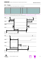
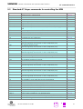
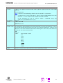
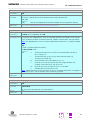
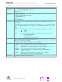
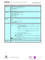
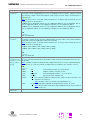
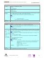
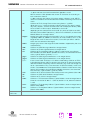
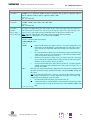
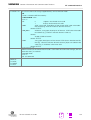
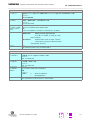
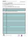
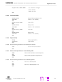
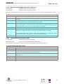
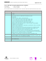
Parameter
t10
t11
t12
t13
t14
t15
t16
t17
t18
t11a
t19
t20
t21
t22
t23
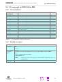
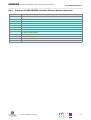
Table 4-3
4.3.4
Siemens Information and Communication Products
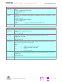
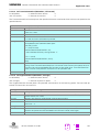
Comment
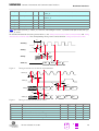
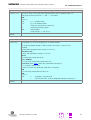
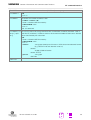
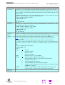
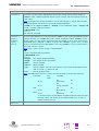
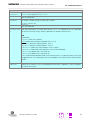
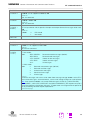
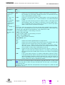
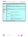
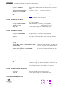
Write high byte to display enable high
Display enable high width
Display enable low width
Display register select setup
Display register select hold
Display chipselect setup
Display chipselect hold
Data setup
Data hold
Display enable high width read extension
Display enable low to write high
Display register select to display enable high
Display chipselect to display enable high
Display enable high to data valid
Data hold
Hardware interfaces
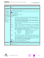
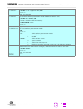
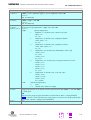
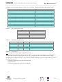
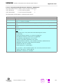
Min.
Typ.
152
Max.
462
462
10
5
10
5
68
15
538
10
200
200
450
0
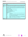
Units
ns
ns
ns
ns
ns
ns
ns
ns
ns
ns
ns
ns
ns
ns
ns
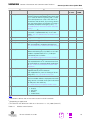
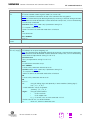
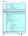
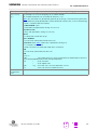
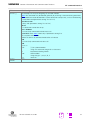
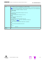
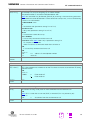
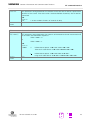
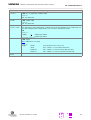
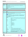
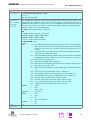
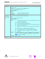
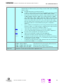
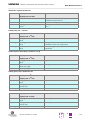
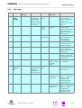
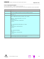
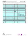
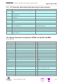
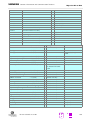
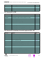
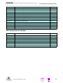
Timing values of display interface
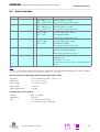
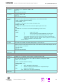
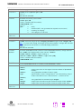
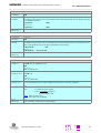
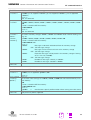
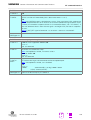
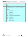
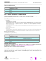
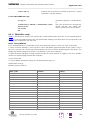
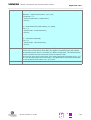
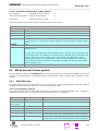
Keypad
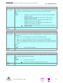
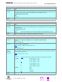
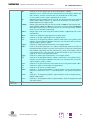
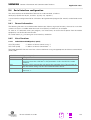
10 Pins for 4*6 keypad matrix.
Signal
KPR0..5
KPC0..3
Function
Keypad row
Keypad column
I/O
I
O
Level
2.8 V
2.8 V
Comments
may be disconnected if unused
may be disconnected if unused
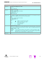
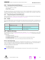
For activation of a key, connect a row signal to the appropriate column signal. The keypad address matrix implemented in the MMI software can be found in Chapter 6.2 “Keypad address matrix” on page 122.
Note: maximum input speed: 1 key per 400ms
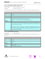
4.3.5
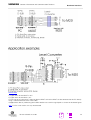
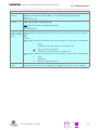
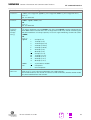
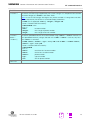
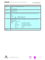
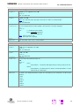
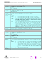
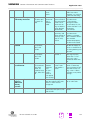
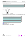
Serial Interface RS323 (V.24) Connections and signals
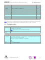
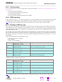
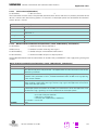
The Serial Interface can be used for:
• AT command interface
• Software download (SW update), see 8.5 “SW download (Version update)” on page 168
• serial interface for data/fax/SMS services.
Note:
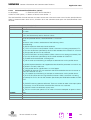
External level converter is necessary for V.24 level when using the M20.
The M20T has a direct 9 pin serial interface port.
A
Version 5 dated 01.03.99
23