1
IT-2000W
(Windows version)
Technical Reference
Manual
(Version 1.00 )
April 1998
Casio Computer Co., Ltd.
Copyright ©1998. All rights reserved.
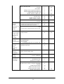
Table of Contents
Chapter 1
1.1
1.1.1
1.1.2
1.1.3
1.1.4
1.1.5
1.2
1.2.1
1.2.2
1.3
Chapter 2
2.1
2.1.1
2.1.2
2.1.3
2.2
2.2.1
2.2.2
2.2.3
2.2.4
2.2.5
2.2.6
2.3
2.3.1
2.3.2
2.3.3
2.3.4
2.3.5
2.3.6
2.3.7
2.3.8
2.3.9
2.3.10
2.3.11
2.3.12
Chapter 3
3.1
3.2
3.3
3.4
3.5
3.6
3.7
3.8
3.9
Preface
Overview
Features of System
Development Concept
Hardware
Software
Basic Specifications
Model Name
System Configuration
Hardware Block Diagram
Supported Software
Precautions
Basic Software
Overview
Software Configuration
Memory Map
Drive Configuration
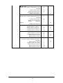
Basic System Operation
Overview
Power ON Process
Power OFF Process
Battery Voltage Monitoring Process
Low Consumption Current Process
How to Replace or Recharge Batteries
Supported Devices
Display Unit
EL Backlight
Touch Panel
Disk
Serial Communication
PC Card
Clock Timer
Buzzer
Barcode Reader
Infrared Communication (IR)
Keys
Sensors
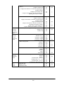
System Menu
Overview
Basic Operation
List of Functions
Key Click Sound Setup
Buzzer Volume Setup
Contrast Adjustment
Auto Backlight Setup
Auto Power OFF Setup
Touch Panel Calibration
2
5
6
6
6
6
6
7
8
9
9
10
13
16
16
16
17
18
19
19
21
25
27
31
34
36
36
38
39
40
42
44
46
47
48
49
50
51
52
52
53
53
54
55
56
57
58
59
Chapter
Chapter
Chapter
Chapter
Chapter
3.10
3.11
3.12
3.13
3.14
3.15
3.16
3.17
4
4.1
4.2
4.3
5
5.1
5.2
5.2.1
5.2.2
6
6.1
6.2
6.3
6.4
6.5
7
7.1
7.2
7.2.1
7.2.2
7.3
7.3.1
7.3.2
7.4
7.4.1
7.5
7.5.1
7.5.2
7.6
7.6.1
7.6.2
7.7
7.7.1
7.7.2
7.8
7.8.1
7.8.2
7.9
7.9.1
7.9.2
7.9.3
7.9.4
8
8.1
8.2
8.3
8.3.1
8.3.2
8.3.3
8.4
8.4.1
YMODEM Utility
FLINK Command
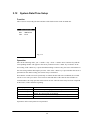
System Date/Time Setup
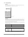
Command Prompt
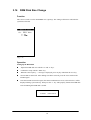
RAM Disk Size Change
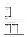
Disk Format
System Initialization
Password Entry
MS-DOS
Overview
How to Write CONFIG.SYS and AUTOEXEC.BAT
Card Boot
MS-Windows
Overview
Installation of MS-Windows
Demonstration Installation
Application Installation
Keyboard Controller
Overview
Keyboard Control
Touch Panel Control Function
Sensor Control
Backlight Control
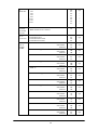
Drivers
Overview
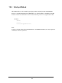
System Driver
Function
Startup Method
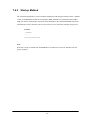
Clock Control Driver
Function
Startup Method
Keypad Driver/Hardware Window Manager
Function
PenMouse Driver
Overview
Startup Method
Virtual Keyboard Driver
Function
Startup Method
System Library (main program file)
Function
Operation Method
Display Driver
Function
Startup Method
COM Driver for IrDA
Overview
Windows 3.1 Communication Functions
Setting Up WIN.INI File
Installation Method
Application Development
Overview
Notes on Developing Application
Development Environment
Development Environment
Application Development Library
Simulation Driver
Program Development Procedure
Creation of Execution File
3
61
65
68
69
70
72
74
75
76
76
78
81
84
84
85
85
86
87
87
88
90
91
92
95
95
96
96
96
97
97
98
99
99
100
100
101
102
102
103
104
104
104
105
105
105
107
107
109
135
139
141
141
142
143
143
143
144
145
146
8.4.2
8.4.3
8.4.4
8.5
8.5.1
8.6
8.6.1
8.6.2
8.6.3
8.6.4
Chapter
APPENDIX
APPENDIX
APPENDIX
8.6.5
8.6.6
9
9.1
9.2
9.3
9.4
9.5
9.6
9.6.1
9.6.2
9.6.3
9.6.4
9.6.5
9.6.6
9.6.7
9.6.8
9.7
9.8
9.9
9.10
A
B
C
Debugging Through Simulation
Operation Check on IT-2000 (Using COM2KEY/XY)
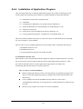
Installation of Application Program
Simulation Driver
System Driver Simulator (SysCall.DLL)
Library
Overview
System Library
Keypad Library
OBR Library
Setting Operation Mode/DT-9650BCR
Setting Operation Mode/DT-9656BCR
YMODEM Library
FLINK Library
Utility
Overview
Calculator Utility
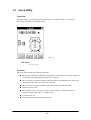
Clock Utility
Calendar Utility
Remaining Battery Voltage Display Utility
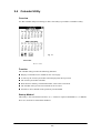
FLINK Utility
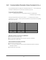
Communication Parameter Setup Command
File Transmission (/S)
File Reception (/R)
File Append (/A)
File Deletion (/D)
File Move/Rename (/N)
Idle Start
Termination Codes and Messages
XY Utility
Reverse Video Utility
COM2KEY Utility
Windows Installation Utility
TFORMAT.EXE
PC Card Driver
Acquisition of Suspend/Resume Event and
Power Status
4
147
149
150
152
153
157
157
158
196
213
223
228
233
239
257
257
258
260
262
263
264
265
267
269
271
272
273
274
275
277
282
283
284
291
292
295
Preface
The IT-2000 Technical Reference Manual (hereinafter referred to as this document) is provided to
assist the user in developing programs to run on the Casio IT-2000 (hereinafter referred to as this
terminal or IT-2000 or HT). Microsoft C/C++ Ver.7.0 or later, and the manuals supplied with it, is
required to develop programs for this terminal.
Read Chapter 1 of this manual in its entirety to understand the features of this terminal.
Important notices to user
The information contained in this document may be modified without prior notice.
Casio Computer Co., Ltd. shall not be liable for any outcome that result from the use of this
document and the terminal.
Copyright notice
The contents of this document are protected by the Copyright Law of Japan.
This document may not be reproduced or transferred in part or in whole, in any form without
permission from Casio Computer Co., Ltd.
Copyright © Casio Computer Co., Ltd. All rights reserved.
About MS-DOS 6.22
The MS-DOS copyright is the proprietary of Microsoft Corporation in the United States and is
protected by the United States Copyright Law and International Treaty provisions.
The MS-DOS software shall not be modified, reverse-engineered, decompiled, or disassembled. Any
form of reproduction is also absolutely prohibited.
About MS-Windows
The MS-Windows copyright is the proprietary of Microsoft Corporation in the United States and is
protected by the United States Copyright Law and International Treaty provisions.
The MS-Windows software shall not be modified, reverse-engineered, decompiled, or disassembled.
Any form of reproduction is also absolutely prohibited.
About trademarks
AT and IBM PC/AT are registered trademarks of International Business Machines
Corporation in the United States.
MS, MS-DOS, Microsoft C/C++, Visual C ++, Visual Basic, and MS-Windows are registered
trademarks of Microsoft Corporation in the United States.
5
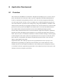
1.
Overview
1.1
Features of System
1.1.1
Development Concept
The IT-2000 is a data collection terminal for business use. After years of refinement Casio
Computer Co., Ltd. has developed its hand-held type terminals so that they yield high speed and
a high functionality in comparison to general personal computers. This allows improved efficiency
in software development.
It has adopted the IBM PC/AT architecture and incorporated an IBM PC/AT compatible BIOS.
It uses MS-DOS Ver. 6.22 and MS-Windows for its OS. This has drastically improved the software
development environment and compatibility to IBM PC/AT family applications.
The adoption of a power-saving type 32-bit CPU, the Intel 80486GX, allows the terminal to operate
continuously for eight hours (when the backlight is off).
1.1.2
Hardware
Global IBM PC/AT architecture standard is adopted.
Compact design: 85 (W) x 196 (L) x 30 (H) mm, 430 g (approx.)
Uses a 32-bit CPU (Intel 80486 GX) for 25 MHz high-speed operation.
High-resolution (192 x 384 pixels), large-size liquid crystal touch panel.
Supports various interfaces, including RS-232C (8-pin, 14-pin), IR, and PC card.
High environmental adaptability: Operation temperature at between -5 and 50 , water splash
proof capability conforms to the IPxII standard, etc.
1.1.3
Uses a small-size, large capacity lithium-ion battery pack as the main battery.
Incorporates a large capacity flash ROM drive as the user drive.
Software
MS-DOS Ver. 6.22 and MS-Windows as the operating system.
IBM PC/AT-compatible BIOS makes it easy to develop user application programs.
Uses APM 1.1, for advanced low-power consumption capability.
6
PC card slot conforms to PCMCIA Release 2.1 supporting various PC cards.
Implements IrDA 1.1 protocol for high-speed infrared communication.
System menu makes it easy to maintain the IT-2000 and install user application programs.
Provides various development support tools including C-language libraries and communication
utilities for developing business application programs.
1.1.4 Basic Specifications
IT-2000
Architecture
IBM PC/AT architecture
External dimensions and weight
Dimensions
: 85 (W) x 196 (L) x 30 (H) mm
Weight
: 430 g (approx.)
CPU
Intel 80486GX(32-bit)
Memory
DRAM
: 4 MB
F-ROM
: 0/4/8/12/16/24 MB (refer to Chapter 1.1.5)
MASK ROM
: 8 MB, Windows file
BIOS ROM
: 1 MB (BIOS section: 256 KB, Drive C image: 768 KB)
Display and input
LCD panel
: 192 x 384 dots (FSTN semi-transparent LCD), with EL
backlight
Touch panel
: Analog, 192 x 384 dots
Interface
8-pin
: RS-232C
14-pin
: RS-232C
IrDA
: Standards 1.0/1.1
PC Card
: PCMCIA Release 2.1
Power supply
Main battery
: Lithium-ion battery pack (x 1)
Sub-battery
: Lithium-vanadium battery (x 1), lithium battery (x 1)
Operating hours
: 8 hours (if backlight off)
Backup period
: 2 weeks (approximately)
Environment conditions
Temperature
: Operation -5 to 50
: Storage -10 to 55
Water-splash proof
: Conforms to IPxII standard
Software
BIOS
: IBM PC/AT compatible
OS
: MS-DOS Version 6.22, MS-Windows
F-ROM
: NAND flash file system
Basic functions
: Suspend/Resume, Auto Power OFF, Auto Backlight OFF,
Auto Backlight ON/OFF with light intensity detection,
Auto Power ON with timer/ring signal/detection of
mounted I/O Box, Battery voltage monitoring function
7
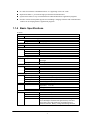
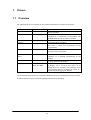
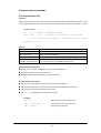
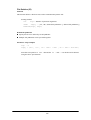
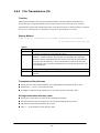
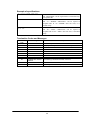
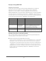
1.1.5
Model Name
The following IT-2000s of Windows version will be available. For price of each model, please
consult with your local Casio representative.
Model
IT-2000W20
IT-2000W30
IT-2000W40
IT-2000W50
IT-2000W60
RAM
4 Mbytes
4 Mbytes
4 Mbytes
4 Mbytes
4 Mbytes
FlashROM
4 Mbytes
8 Mbytes
12 Mbytes
16 Mbytes
24 Mbytes
8
Total
8 Mbytes
12 Mbytes
16 Mbytes
20 Mbytes
28 Mbytes
Remark
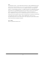
1.2
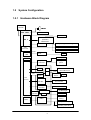
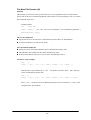
1.2.1
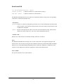
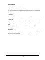
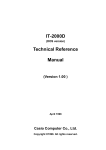
System Configuration
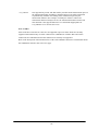
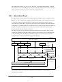
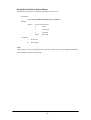
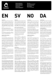
Hardware Block Diagram
CPU
i486GX
1
Power switch
MASK ROM
FLASH ROM
(DINOR)
BIOS/DOS
Battery voltage monitoring sensor
DRAM
A/D
converter
UART/
SIR
Temperature sensor
Illumination sensor
COM 1
Buffer
8-pin
Key
RTC
Keyboard
controller
Analog touch
panel
ASIC
RTC
IrDA
Driver/Receiver
IrDA 1.1
IrDA 1.0
COM 2
RS-232C
driver
16550
BUS
Controller
14-pin
PC card
PC card slot
controller
NAND
interface
VGA
controller
NAND FLASH
BL controller
LCTC
EL Backlight
LCD
Lithium-ion
battery
PMU
PMU
Primary sub-battery
Secondary sub-battery
9
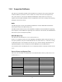
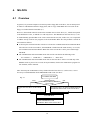
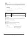
1.2.2
Supported Software
The software used with this terminal can be divided into two categories: the system software that
includes the BIOS, OS, and device drivers and the user software such as the development tools.
The system software is stored on the DINOR FLASH ROM (1 MB), and the user software is
supported from the SDK CD-ROM (version 4.0) supplied by Casio at free of charge. The following
paragraphs describe the software.
BIOS
The BIOS program is stored in the DINOR FLASH ROM. 256 KB of DINOR FLASH ROM is
allocated specifically as the BIOS storage area.
The BIOS of this terminal consists of the standard PC/AT BIOS section, PEN BIOS for supporting
the touch panel, extension BIOS for supporting devices inherent to this terminal, and APM BIOS for
attain the low-power consumption capability.
MS-DOS Main Part
The main part of the MS-DOS Ver. 6.22 is stored in drive (C:).
In drive (C:) 768 KB of memory area in the DINOR FLASH ROM (1 MB) is allocated. Because of
the capacity limitation, only the essential MS-DOS files are stored in drive (C:). Therefore, if using
an MS-DOS file that is not included in the main part, copy it from the Backup CD-ROM (title on
CD-ROM: MS-DOS version 6.22 Software) to the F-ROM drive (D:) or RAM disk (A:).
For information about each MS-DOS file refer to an MS-DOS manual, commonly available at book
stores.
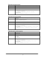
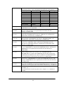
Device Drivers and System Files
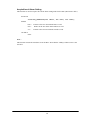
These files must be loaded via CONFIG.SYS or AUTOEXEC.BAT at boot-up. These files are all
stored in drive (C:).
File name
SYSDRV.SYS
TIME.SYS
CS.EXE, etc.
CASIOAPM.COM
ENDATA.COM
CKRAMDSK.EXE
CKRAMDSK.DAT
CALIB.EXE
SYSMENU.EXE
HWWMAN.EXE
KEYPAD.EXE
KEYPAD.DAT
Storage location
Basic drive (C:)
Basic drive (C:)
Basic drive (C:)
Basic drive (C: )
Basic drive (C:)
Basic drive (C:)
Description
System driver
Clock control driver
PC card driver
Touch-panel enabler
ATA card-related data
RAM disk checker
Basic drive (C:)
Basic drive (C:)
Basic drive (C:)
Basic drive (C:)
Calibration
System Menu
Hardware window manager
Keypad
10
TFORMAT.EXE
Basic drive (C:)
F-ROM drive formatter
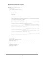
Windows Driver
These drivers are necessary for the Windows to run on IT-2000. Download to F-ROM drive (D: ).
File name
VGA_C.DRV
VGA_NC.DRV
PENMOUSE.DRV
VKD.386
IRDA.DLL
IRCOMM.DRV
Storage location
MASK ROM drive (E: )
Description
Display drivers
SDK
SDK
SDK
Mouse driver
Virtual key driver
IR communication drivers
Utilities
For information about the utilities refer to Chapter 9 "Utility".
File name
WCAL.EXE
WCALC.EXE
WCLOCK.EXE
WCHKBATT.EXE
XY.EXE
FLINK.EXE
LCDREV.EXE
Storage location
SDK
SDK
SDK
SDK
Basic drive (C:)
SDK
11
Description
Calendar utility
Calculator utility
Clock utility
Power status indication utility
XY utility (DOS program)
FLINK utility (DOS program)
Reverse video utility
(DOS program)
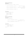
Development Tool Libraries
All the libraries of Windows are provided either as Dynamic Link Library (DLL) or as Visual
BASIC Custom Control (VBX). To use these libraries, download first to a directory in F-ROM
drive (D: ). The files, *.LIB and *.H, are needed when you develop an application program.
File name
LIBSYSW.LIB
SYSCALL.DLL
SYSCALLP.DLL
SYSLIB.H
PADCTRL.VBX
PADCTRL.H
LIBOBR.LIB
OBRLIB.H
OBRLIB.DLL
LIBYMOD.LIB
YMODEM.DLL
YMODEM.H
FLINK.LIB
FLINK.DLL
FLINK.H
COM2KEY.EXE
PMON.COM
PMOFF.COM
Storage location
SDK
Description
System library
SDK
Keypad library
SDK
OBR library
SDK
YMODEM utility library
SDK
FLINK utility library
COM > KEY for DEBUG
(DOS program)
Switching DOZE mode ON/OFF
(DOS program)
Basic driver (C: )
Basic drive (C:)
12
1.3
Precautions
If reading the internal clock with INT21h the significant data should include and be limited to
the seconds digits. On this terminal the time is read directly from the RTC so that the correct
time can be attained at any moment, even during extended continuous use. As a result the 1/100
of a second digit is ignored. (refer to Chapter 7.3 “Clock Control Driver”.)
To count time, the counter of DOS or the function provided for reading time must be used.
Time tick count of Windows will be behind 1 second in every 2 minutes.
If it is necessary to reboot the system from an application, use the dedicated system library.
However, the reboot operation that uses INT19h of the BIOS I/F does not work.
Many commercial PC programs use a VGA screen (80 (H) x 25 (V)). If these programs are run
on this terminal (24 (H) x 24 (V)) part of the message may not be displayed on the screen.
For example, some of messages displayed by Windows appear partly (left side of the messages
only) on the screen.
Writing to a PC card should always be performed by terminating the write action through the
flash-out process. Otherwise, if system operation is suspended while writing to an SRAM card
or ATA card, the data on the card may be damaged. To activate this flash-out process use the
“_dos_commit()” function of Visual C/C++ or Commit Function (68h) of DOS.
VGA controller is installed in IT-2000. Logically, it can display 16 different colors each in
single color though only 4 colors at a time are distinguishable. In case of development of
application program in single color, by having four colors, such as RGB (255,255,255), RGB
(192,192,192), RGB (128,128,128), RGB (0,0,0), will help you create an easy-to-see
application program.
Note:
If you wish to select a dither color, first display it on the screen to make sure. Due to technical
reasons the display of the B/W LCD may change to reverse video if an application program
developed by the user on a PC is executed without modification on this terminal. To restore the
normal display use the Reverse Video Utility (refer to Chapter 9.8 “Reverse Video Utility”).
Key input operation is disabled for about one second after the Power has been turned off/on.
This is not a malfunction. This occurs because the monitoring timer starts operating the moment
the Power switch is turned on and does not allow any key input for about one second until this
timer expires. Thus, key input is not possible.
13
If an LB1 event (low main battery voltage) occurs, the alarm buzzer starts sounding and system
operation is suspended about 10 minutes later. If the alarm buzzer starts sounding, terminate the
current operation as soon as possible and recharge the main battery.
This system will not execute an alarm indication to be displayed on the LCD screen for an LB2
event (low sub-battery voltage) or LB3 event (low SRAM card battery voltage). Therefore, the
application program side must acquire these alarm status via the system library and display an
appropriate alarm message on the screen.
If the volume of the buzzer is set to zero by the System Menu or system library, the LB1 (low
main battery voltage) alarm will not be heard. Also, other sounds issued by the system will be
inaudible.
If the system is booted from a PC card and if a large-size program that resides on the card is
called from AUTOEXEC.BAT, an error may result. To avoid this problem refer to Chapter 4.2
“How to Write CONFIG.SYS and AUTOEXEC.BAT".
The time limits that can be set for the Auto Power OFF (APO) function are 0 minute, 1 minute
and 30 seconds, 2 minutes and 30 seconds, up to a maximum of 15 minutes and 30 seconds.
This timer has an error of +/-23 seconds.
Do not open the battery compartment lid while the power is on. If it is opened accidentally, an
emergency alarm sounds. In case such the event occurs, close the lid at once.
When you change the main battery, be sure to switch off the power before opening the lid.
An SRAM card once formatted with the DT-9000 cannot be used or formatted with IT-2000.
If the battery pack is installed for the first time after purchase, or if it is installed after the
IT-2000 unit has not been used for a long period of time, install the battery and wait for
approximately eight seconds before turning the power on. This must be done because it takes
approximately eight seconds until sufficient power can be raised for the emergency process.
And, during this interval the power cannot be turned on even if the Power switch is turned on.
If the power is turned on for the first time after purchase and there is no installed application,
the System Menu will always appear. To start up the application, the application must be
installed first on the IT-2000. (refer to Chapter 8.4.4 “Installation of Application Program” )
14
The backlight is turned off by means of the ABO (Auto Backlight OFF) function. However, it
is turned off 1.3 seconds after the setup time. This is because the system has 1.3 seconds of
monitoring time before the internal timer is started.
During the process of loading Windows after boot-up, do not press the Power switch.
Do not press the Power switch because a processing request is issued before the process handler
is installed, resulting that the processing following the request can no longer be achieved.
This terminal cannot avoid encountering the bugs inherent to Windows. If, for example, the File
Manager is used, dates (such as a date of file creation, etc.) on and after the year of 2000 will
not be displayed correctly. This is caused by a bug within Windows. However, note that the
internal clock will operate properly after the year 2000.
The touch panel calibration program is not supported as part of Windows. Therefore, if
calibrating the touch panel with Windows, terminate Windows and execute the calibration
program from the DOS prompt screen, then return to Windows.
The input process from the touch panel should be designed so that every designation can be
accepted with a single click. On this terminal a double-click can be ignored.
For this system, the two display drivers of VGA_C.DRV and VGA_NC.DRV are provided.
The former will display the mouse cursor and the latter will not display the cursor nor the sandglass cursor.
While a file in SRAM card is being opened under Windows, the operation of the access to the
card is aborted if suspend is executed. This will cause INT24 error when the access to the
SRAM card for writing or closing is continued after the resume. When you use an SRAM card
under Windows, please be sure to perform the operation steps in sequence of “open write close”.
Do not input “^P” from the DOS prompt. If it is input, “^P” requests DOS to redirect console
output to printer. However, because the IT-2000 does not have a built-in printer, it will enter
into wait mode.
For information about the system library, refer to Chapter 8.6.2, "System Library".
For information about the low voltage alarm notification function refer to Chapter 2.2.4 "Battery
Voltage Monitoring Process"
.
15
2.
Basic Software
2.1
Overview
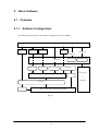
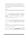
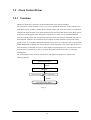
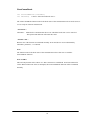
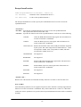
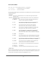
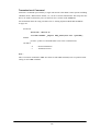
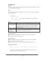
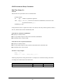
2.1.1
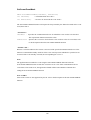
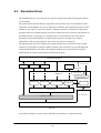
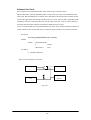
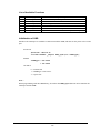
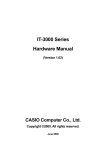
Software Configuration
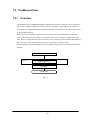
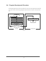
The following diagram shows the software configuration of the IT-2000W.
Application Program
LibSYSW.LIB
LibOBRW.LIB
LibYMOD.LIB
FLINK.LIB
Mouse Event
Display Req.
VGA_NC.drv
MS-Windows
OBRLIB.DLL
YMODEM.DL
PADCTRL.VBX
PenMouse.drv
FLINK.DLL
AT Architecture
LibSYSW.LIB
IrDA Driver
&
ROM BIOS
SysCall.DLL
VKD.386
Handy Terminal Original Hardware & ROM BIOS
Fig. 2.1
16
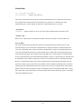
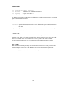
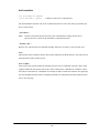
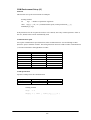
2.1.2
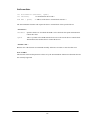
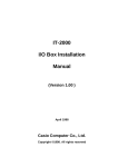
Memory Map
The memory map of the IT-2000 is as follows.
Extended Memory
100000h
ROM BIOS
NAND DISK BIOS/VGA BIOS
Memory Mapped Disk I/F
PC Card I/F
EMS Windows 16 KB x 4
Reserved
0F0000h
0E0000h
0DC000h
0D8000h
0C8000h
0C0000h
Video Buffer
128 KB
0A0000h
System RAM
640 KB
000000h
Fig. 2.2
17
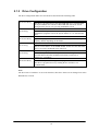
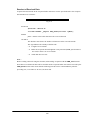
2.1.3
Drive Configuration
The drive configuration differs for each model as described in the following table:
Drive A:
[Read and Write]
Drive C:
[Read Only]
Drive D:
[Read and Write]
Drive E:
[Read Only]
Drive F:
[Read Only]
Drive G:
[Read and Write]
RAM disk
This drive is prepared for use after the RAM disk size is specified from
the System Menu. The contents of this RAM disk will not be erased
through a boot process or by pressing the RESET switch.
Basic drive (DINOR FLASH ROM)
This drive starts up MS-DOS. The main body of MS-DOS and
maintenance programs such as the System Menu, etc., are stored in this
drive.
F-ROM drive
Application programs are stored on this drive. The drive size (storage
capacity) differs depending on the model.
Drive for Windows files
A ROM that stores Windows files is assigned to the drive E.
This is a reserved drive on IT-2000D models. In this case note that if this
drive is accessed , an INT24h error will occur.
Drive for booting up from card
This read-only drive functions only while a card is being booted.
For information about the mechanism of booting a card refer to
Chapter 4.3 “Card Boot”.
PC card drive
This drive is required if the application program accesses the PC card.
This drive is prepared for use by loading the PC card driver via
CONFIG.SYS.
Note:
The drive letter of each drive is reserved. Therefore, these drive letters are not changed even if the
RAM disk is not used.
18
2.2
Basic System Operation
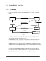
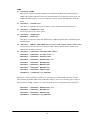
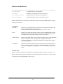
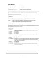
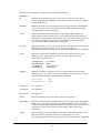
2.2.1
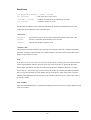
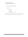
Overview
Basic operation of this system on the terminal consists of the suspend/resume process and boot
process operated by means of the Power switch and RESET switch, as shown in the following
diagram.
OFF STATE
ON KEY
ON STATE
Application BOOT
OFF EVENT
RESET SWITCH
OFF EVENT
System Menu BOOT
OFF Process
OFF Process
ON EVENT
ON Process
System Menu
RESET SWITCH
System Menu BOOT
SUSPEND
STATE
ON KEY
System Menu BOOT
INITIAL STATE
Fig. 2.3
During normal operation the system status will move between the ON state and the OFF state,
shown in the above diagram, by pressing the power key.
The SUSPEND state is a state from which the previous state can be returned to at any time. The
process of returning from the SUSPEND state to the ON state is called the resume process.
The RESET switch is used to either re-start the system or to initiate the System Menu, which is the
maintenance program. Press this RESET switch to start hardware initialization followed by initiation
of the System Menu. This process is called the System Menu boot process.
If an OFF event occurs while the System Menu is operating, the system shifts to the OFF state.
If the ON key is pressed in the OFF state, the boot process is executed again and an appropriate
application program will be loaded. This process is called the application boot process.
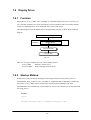
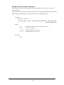
19
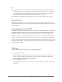
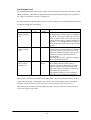
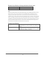
The following table summarizes the power-on processes provided for this terminal.
System Menu boot
process
Application boot process
Resume process
Always executes CONFIG.SYS and AUTOEXEC.BAT located
in drive (C:) for starting up the MS-DOS.
Searches for CONFIG.SYS and AUTOEXEC.BAT prepared
by the user and starts up MS-DOS from the drive where they are
located.
Restores the memory conditions that existed before the power
was turned off and continues operating according to the
conditions.
20
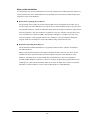
2.2.2
Power ON Process
Overview
The ON process is provided to make the system ready for use (ON state). The actual process varies
depending on the settings at that point in time and the last OFF factor (the cause of the OFF action).
ON factors:
Pressing the Power switch
Pressing the RESET switch
Power ON alarm
Reception of RING signal
Mounting on the I/O Box
OFF factors:
Pressing the Power switch
Pressing the RESET switch
Auto Power OFF (APO)
Power OFF by software
Auto Power OFF due to lower battery voltage
Emergency Power OFF due to lower battery voltage
Note:
For more information power OFF factors refer to Chapter 2.2.3 "Power OFF Process".
This ON process is divided into two processes: the "Resume process" for continuing the previous
process and the "Boot process" for re-loading MS-DOS. The Boot process can be further broken into
the "Application boot" and the "System Menu boot" processes.
Fig. 2.4
Boot Process
Application Boot Process
Resume Process
System Menu Boot Process
ON Process
Application Boot Process
Searches CONFIG.SYS and AUTOEXEC.BAT files according to the priority given to each
drive and, if these files are found, sets the drive where these files are located as the current drive.
(refer to ”Application Boot Process” on the next page).
21
System Menu Boot Process
Press the RESET switch to set the drive C as the current drive, and load MS-DOS from that
drive. As a result, the System Menu that includes the maintenance program will be initiated
(refer to “System Menu Boot Process” on this page).
Resume Process
This process restores the conditions that existed before the power was most recently turned off.
Any application program that was running at that point in time can be continued.
The contents of the above listed processes will be described in the following sections.
Application Boot Process
The application boot process is used to initiate application programs that have been installed in the
system by the user. The main system will search for CONFIG.SYS and AUTOEXEC.BAT files
according to the priority given to each of the following drive Gs prior to booting MS-DOS.
The system assigns the first drive on which they are found as the current drive, and boots MS-DOS
from it. Consequently, if the CONFIG.SYS and AUTOEXEC.BAT files created by the user are
located on one drive, MS-DOS will be booted from the drive assigned as the current drive. Under
factory defaults it is apparent that the CONFIG.SYS and AUTOEXEC.BAT files created by the
user cannot be found. If this occurs, therefore, the CONFIG.SYS and AUTOEXEC.BAT files
located in drive C: are selected and the System Menu will be initiated.
Priority of the drives:
If the F-ROM drive is installed
[Card drive (F:)] -> [RAM drive (A:)] -> [F-ROM drive (D:)] -> [Basic drive (C:)]
If the F-ROM drive is not installed
[Card drive (E:)] -> [RAM drive (A:)] -> [Basic drive (C:)]
Note:
The RAM disk (A:) is valid for use only if the setup is made in the System Menu.
System Menu Boot Process
The System Menu boot process is used to initiate the System Menu, which is nothing but a
maintenance program for this terminal system. The System Menu boot process will be executed only
if the RESET switch at the rear of the main unit is pressed.
If, in addition, a power OFF factor is encountered during the execution of the System Menu, the next
boot process will be the application boot process.
22
Note:
The RESET switch can be used not only for initiating the System Menu but also as the forced
restart switch when the user application program under development hangs. However, note that
if the RESET switch is pressed while the disk is being written to, the data may be corrupted.
Therefore, the RESET switch should be pressed only while the power is off.
Clock data or information on the RAM disk will not be lost if the RESET switch is pressed.
Resume Process
When the power is turned on the resume function resumes system operation under the conditions
that existed the last time the power was tuned off. Application programs are continued as soon as the
power is resumed.
Setup of Resume Process ON/OFF
The default settings have been made so that every OFF factor encountered during the operation of an
application program is the objective of the resume process. However, these default setting can be
modified so that the system reacts differently to OFF factors by means of the system library. For
example, according to the default settings, pressing the Power switch will suspend and resume the
execution of an application program. However, it is also possible to simply reboot the system with
the Power switch without activating the resume function if such a setup is made. However, note that
this setup is not permanent. The resume process is replaced by the boot process once only right after
the system library is called.
.
ON Factors
Various ON factors used to turn on the system are explained below.
Pressing the Power switch
If the Power switch is pressed while the system is off, the system power can be tuned on. When
the power is turned on the system operation sequence proceeds as described in "Relationship
between OFF Factors and ON Processes" on page 24.
Pressing the RESET switch
Press the RESET switch to turn on the system power. In this case the System Menu will always
be initiated.
23
This terminal has the Auto Power ON function which automatically starts the system. This Auto
Power ON function can operate in one of the following three ways:
Auto Power ON function (only affects the resume process) activated by alarm
The system power can be turned on (resumed) at the specified time by means of an alarm.
However, this will not function if the next start-up method is set to the boot process in the system
library.
Auto Power ON function activated by the RING signal
This function can be used if a modem is connected to the 14-pin expansion interface. In this case
the system power can be turned on by the detection of the RING signal from the modem.
Remember that Power ON by means of the RING signal is prohibited by default. Execute this
function using the system library to enable the Power ON function to be activated by the RING
signal. System operation after the power is turned on follows the sequence described in "
Relationship between OFF Factors and ON Processes" on this page.
Auto Power ON activated by mounting on the I/O Box
The system power can be automatically turned on as soon as this terminal is mounted on the I/O
Box. However, this function is effective only if power is supplied to the I/O Box. This function is
enabled by default, however, it can be disabled using the system library. System operation after
the power is turned on proceeds according to the sequence described in "Relationship between
OFF Factors and ON Processes".
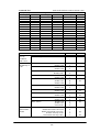
Relationship between OFF Factors and ON Processes
As described in the above overviews, the ON process (the Boot process or Resume process) will run
differently depending on the last OFF factor (what caused the OFF) and the conditions that existed
when the power was turned OFF. The following table shows the relationship between the OFF
factors and the ON processes that take place the next time the power is turned on.
OFF factor
Power switch
Auto Power OFF
Software OFF
Low battery voltage
(LB1)
Low battery voltage
(LB0)
RESET switch pressed
If an application is running
Resume process or application
boot process (see note below)
If the System Menu is on
Application boot process
Resume process
System menu boot process
System menu boot process
Note:
Depends on whether the resume function is enabled or disabled. With this setup the next boot
process can be designated as the Application boot process.
24
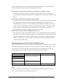
2.2.3
Power OFF Process
Overview
Turns off the system power. However, the power to all the devices is not turned off and some can be
used for storing the information required for the next resume operation. This process is called the
suspend process and the state of the system while off is called the suspend state.
The suspend process can be divided into two categories: one is the normal suspend process which is
the usual off method and the other is the critical suspend process to execute the emergency escape
process for protecting the system from drops or bumps. Either of these suspend processes will be
selected depending on the OFF factor, as described later.
Normal Suspend Process
If the Power switch is held down for more than one second while system is on, the system power
will be turned off. The process that takes place at this time is the normal suspend process. Before
this suspend process is executed, the application currently running is informed of the suspend
request (OFF factor) by the system. Then the system stores the information required for resumption
and turns off the power.
Hereinafter the suspend process (or OFF process) refers to the normal suspend process.
For information about the method used by each application to detect the occurrence of an OFF factor
(suspend event), refer to Chapter 9.5 “Remaining Battery Voltage Display Utility”.
Critical Suspend
This is a suspend process that takes place in an emergency. Since this critical suspend process should
achieve its escape process with very little power in the system, only essential information can be
retained.
The system will not inform the application currently running of the fact that it is critically
suspended. However, the application will be informed of the fact that it was critically suspended at
resumption.
For information about the method used by each application to receive this information, refer to
Chapter 9.5 “Remaining Battery Voltage Display Utility”.
25
OFF Factors
The OFF factors refer to various causes that make the system enter the OFF state (suspend state), as
follows:
OFF factor
Power switch
Auto Power OFF
(APO)
Power OFF by
Software
Power OFF due to
time-out of low
battery voltage
(LB1) alarm
If main battery
voltage falls to an
inoperable level
(LB0)
Power OFF due to
RESET switch
pressed
Description
System operation can be suspended by holding down the
Power switch for more than a second. (see note)
System operation automatically shifts to the suspend state
if key or touch panel operation is not performed for a
specified period of time.
The duration until Auto Power OFF occurs can be set and
modified through the System Menu or system library.
The system can be made to enter the suspend state by
calling the system library from the application program.
The system will issue an alarm (buzzer) if the remaining
battery voltage falls below the low main battery voltage
alarm level. If this occurs, recharge the battery or replace
it within ten minutes. If the battery is not charged or
replaced the system automatically shifts to the suspend
state to protect the data.
If the terminal is used while the LB1 alarm, mentioned
above, is sounding, the main battery voltage may reach
the LB0 level. If this occurs the system will execute the
critical suspend process and forcibly turn off the power.
Therefore, if the LB1 alarm sounds, recharge or replace
the battery as soon as possible.
Press the RESET switch to forcibly turn off the system
power. If this is attempted to initiate the System Menu, it
is strongly recommended to complete the application
running at present then turn off the system power with the
power switch before hand.
Suspend
Normal
Normal
Normal
Normal
Critical
Restart
For more information about LB0 and LB1, refer to Chapter 2.2.4, "Battery Voltage Monitoring
Process".
For information about the system library refer to Chapter 8.6.2. “System Library”.
For information about the System Menu refer to Chapter 3 “System Menu”.
For information about the method used by each application to acquire a power ON/OFF event, refer
to Chapter 9.5 “Remaining Battery Voltage Display Utility”.
Note:
Hold down the Power switch for more than one second until the power is off. This is done to
prevent the power from accidentally being turned off by the user. In addition, key input will not
be enabled for approximately one second after the Power switch has been pressed.
This occurs because the monitoring timer starts operating the moment the Power switch is
pressed and does not allow key input for about one second until this timer expires.
After this interval, key input becomes possible.
26
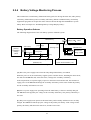
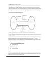
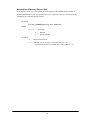
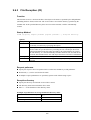
2.2.4
Battery Voltage Monitoring Process
This terminal uses a main battery (lithium-ion battery pack) for driving the main unit, and a primary
sub-battery (lithium battery) and a secondary sub-battery (lithium-vanadium battery) for backup.
Application programs can acquire the status of these batteries through the APM BIOS or system
library. Refer to Chapter 9.5 “Remaining Battery Voltage Display Utility”.
Battery Operation Scheme
The following diagram shows how each battery operates within the system.
Monitors main battery
voltage (LB1 LB0)
Main battery
Monitors
primary
sub-battery
voltage.
(LB2)
Sub-battery
Primary
[A]
[A] Charge
[A](During ON)
(During ON)
SRAM Card
Monitors
SRAM card
voltage. (LB3)
Secondary sub-battery
sub-battery (Rechargeable)
[C]
[A]
[B]
PC Card Slot
Objective devices of backup
Main circuit
(DRAM, etc.)
(CPU and controllers, etc.)
Fig. 2.5
[A] This is the power supply route where the fully charged main battery is installed.
While the power is on, the main battery supplies power to all the devices, including the main circuit,
PC card slot and DRAM, and, at the same time, it charges the secondary sub-battery.
In the suspend state, it stops the supply of power to the main circuit and PC card, but continues to
supply power to the DRAM and charge the secondary sub-battery. In this route neither the primary
nor the secondary sub-batteries are used.
[B] This is a power supply route operating where the main battery is absent or not fully charged.
The DRAM is back-upped by the voltage of the secondary sub-battery. The primary sub-battery is
not used.
[C] This power supply route operates if the main battery and secondary sub-batteries are not fully
charged. The DRAM is backed-up by the voltage of the primary sub-battery. If the voltage of this
primary sub-battery falls below the limit level, an LB2 event occurs.
27
Low Voltage Level
The IT-2000 continuously monitors the voltage of the main battery, the primary sub-battery, and the
SRAM card battery. This allows an application program to determine through the system library if
the voltage of each battery reaches a warning level.
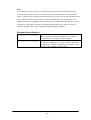
The following table summarizes the low battery voltage warning levels, which application programs
can acquire through the system library.
Name
Low main battery
voltage warning
level
Low sub-battery
voltage warning
level
Low SRAM card
battery voltage
warning level
AbbreviatObjective
Description
ion
battery
LB1
Main battery Indicates that the main battery voltage has
reached a limit level that requires a warning to
be issued. The system sounds the buzzer to
issue an alarm. If this occurs, the user must
replace the main battery within ten minutes. If
the battery is not changed within ten minutes,
the system automatically executes the suspend
process.
LB2
Sub-battery Indicates that the sub-battery voltage has
reached a limit level that requires a warning to
be issued. Since the system does not issue an
alarm, the application program must execute a
warning by acquiring the status from the
system library.
The sub-battery must be replaced according to
the procedure described later.
LB3
SRAM card Indicates that the SRAM card battery voltage
battery
has reached a limit level that requires a
warning to be issued. Since the system does
not issue an alarm, the application program
side must execute a warning by acquiring the
status from the system library.
The SRAM card battery must be replaced
according to the procedure described later.
There is also a main battery inoperable level (LB0). This is the status of the main battery when its
voltage falls below LB1. If this happens, the system executes an emergency power off (critical
suspend). Therefore, this level is also referred to as the emergency escape process level.
This status cannot be acquired from the application side, since the system turns off the power as
soon as the voltage reaches LB0.
28
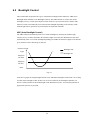
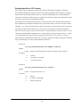
Main Battery Voltage Monitoring
If the main battery voltage reaches LB1, the system issues a warning buzzer. If this warning buzzer
sounds, either start recharging the battery or replace it with a fully charged battery as soon as
possible. If one of these measures is not taken within ten minutes, the system will forcibly turn off
the power for safety. The following diagram shows the main battery voltage against the time axis.
Main
Generate warning buzzer
Battery
Voltage level to operate.
voltage
LB1
(a)
(a)
Turn the power OFF.
(b)
Start recharge.
LB0
(c)
(e)
(d)
Time
10 minutes
Fig. 2.6
(a) If the main battery voltage reaches LB1, the low battery voltage warning alarm sounds.
(b) Unless the main battery is either replaced or recharged within ten minutes, the system power is
automatically turned off to protect the data.
(c) If the main battery voltage falls further and reaches LB0, the system automatically shuts off the
power to the main unit (critical suspend).
(d) If the main battery voltage drops below LB0, the main unit power cannot be turned on even if
the power switch is pressed.
(e) If the main unit is mounted on the I/O Box or connected to the AC adaptor, charging of the
battery is initiated and the main battery voltage will gradually increase.
(f) Once the main battery voltage has been recharged to an operable level, it is possible to turn on
the power to the main unit.
For information about the method used to replace the main battery refer to Chapter 2.2.6 “
How to Replace or Recharge Batteries”.
29
Sub-battery Voltage Monitoring
The sub-batteries are used for system backup while the main battery is being replaced. The subbatteries consists of two units: the primary sub-battery (button-type lithium battery) and secondary
sub-battery (button-type lithium-vanadium battery). The secondary sub-battery is recharged by the
voltage of the main battery.
While the fully charged main battery is installed , the entire system is backed-up by the main battery,
and the secondary sub-battery is charged by the voltage of the main battery. If the main battery is
removed, the job of system backup shifts to the secondary sub-battery. If the secondary sub-battery
voltage drops below the required level while the main battery is removed, the backup job shifts to
the primary sub-battery (refer to “Battery Operation Scheme” on page 27.).
Application programs are permitted, through the system library, to monitor this primary sub-battery
voltage and determine if it is lower than the warning level (LB2). However the system side will not
issue a warning about the low voltage level (LB2) of the primary sub-battery. Therefore, the
application program must monitor the primary sub-battery voltage via the system library and inform
the user that it must be replaced.
For information about the method used to replace the sub-battery refer to Chapter 2.2.6 “How to
Replace or Recharge Batteries”.
SRAM Card Battery Voltage Monitoring
This function monitors the SRAM card battery voltage. Application programs are permitted, through
the system library, to monitor this voltage and determine if it is lower than the warning level (LB3).
However, the system side will not issue a warning about the low voltage level (LB3) of the SRAM
card battery. Therefore, the application program must monitor the SRAM card battery voltage via
the system library and inform the user that it must be replaced.
For information about the method used to replace the SRAM card battery refer to Chapter 2.2.6 “
How to Replace or Recharge Batteries”.
Acquiring Power Status through APM BIOS
This terminal has APM 1.1 installed. This makes it possible for application programs to obtain
information, such as the percentage of battery voltage remaining or the connector status, via the
APM BIOS. For more information refer to Chapter 9.5 “Remaining Battery Voltage Display
Utility”.
Acquiring Power Status through Battery Status Acquisition Utility
With the battery status acquisition utility the user can be advised of the current remaining voltage of
the main battery, sub-battery status, or connector status in real time. For more information refer to
Chapter 9.5 “Remaining Battery Voltage Display Utility”.
30
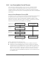
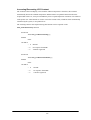
2.2.5
Low Consumption Current Process
This terminal has the APM BIOS installed to provide a low-power consumption capability.
It works in combination with POWER.EXE from Microsoft Corporation. The low-power
consumption capability is further enhanced by the use of unique power management functions,
including Auto Power OFF (APO) function, Auto Backlight OFF (ABO) function, and DOZE/RUN
transit function.
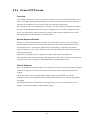
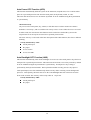
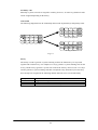
Advanced Power Management Process (APM)
The APM process, which is an interface between the hardware and application programs, has been
developed by the Intel Corporation and Microsoft Corporation for power control purposes.
APM consists of four layers. The layers include hardware, APM BIOS, APM Driver, and the
application, as shown below. With respect to the PC card which is a removable device, the APM
functions are provided from the specific APM driver (CS_APM.EXE).
Applications Layer
APM-aware Applications
PC Card APM Driver
(CS_APM.EXE)
OS Layer
APM Driver (POWER.EXE)
BIOS Layer
Hardware Layer
APM BIOS
APM BIOS Controlled Device
PC Card (Add-in Device)
Fig. 2.7
Basically, APM functions in the following two ways:
APM BIOS, which is in the background, controls the power conditions of each device.
Applications can call the APM BIOS functions to obtain or control the power conditions.
An application that uses the APM BIOS function is called an APM-aware Application. If an
application acquires information related to power conditions via the system library (refer to
Chapter 8.6.2 “System Library”), APM BIOS is actually called within the system library.
It is also possible to directly call APM BIOS from applications. For more information refer to
the APM BIOS manual.
31
Auto Power OFF Function (APO)
This function automatically shifts the system to the OFF state (suspend state) if no event has taken
place for a specified period of time from the touch panel, the keyboard, COM1, or a file.
This time interval has been set to one minute by default. It can be modified using the System Menu
or system library.
About the activity
Any access to the touch panel, key, COM1, or file that causes results in Auto Power OFF is
defined as "an activity", and it is said that "an activity occurs" if one of these devices is accessed.
In other words, the Auto Power OFF function can be said to have shifted the system to the
suspend state if no activity has occurred for a specified period of time.
The term "activity" is also used in the later description of the ABO function, but it has a different
meaning.
Activity monitored by APO:
Touch panel input
Key input
Access to files
Access to COM1
Auto Backlight OFF Function (ABO)
This function automatically turns off the backlight if it no access to the touch panel or keys has been
attempted for a specified period of time. This time interval has been set to twenty seconds by default.
It can be modified using the System Menu or system library. Touch panel or key sensing is
performed by the keyboard controller. This keyboard controller not only processes key input or
touch panel input, but it also simultaneously detects activity while executing various background
processes. Consequently, the limit value set as the Auto Backlight OFF time will not be accurate
down to the seconds. The accuracy of this setup value is 10 percent.
Activity monitored by ABO:
Touch panel input
Key input
32
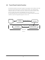
DOZE/RUN Transit Function
On this terminal the system will reduce the clock speed of the built-in CPU if no activity (access to
the touch panel, keys, COM1, or file) has occurred for a specified period of time (four seconds).
The state in which the CPU clock speed has been reduced is called the "DOZE state" and the state in
which the CPU is operating at full speed is called the "RUN state". If an activity occurs in the
DOZE state, the system returns to the RUN state. The DOZE/RUN transit function automatically
switches between the DOZE and RUN states.
Touch panel
No activity for
Key
a specified period
COM1
of time
File access
RUN
DOZE
Full speed
Low speed
Touch panel
Generation of
Activity
Key
COM1
File access
Fig. 2.8
Usually, application programs do not have to anxious about the RUN/DOZE state.
The user may tolerate the operation speed since the system shifts to the RUN state whenever the user
attempts an action.
However, the clock speed is quickly reduced and CPU operation is slow if high-speed processing is
attempted intentionally or if system operation continues without user action (e.g. in a long
calculation). In order to avoid this, disable the power management function by means of the system
library (refer to Chapter 8.6.2 “System Library”.).
Activity causing RUN/DOZE transition:
Touch panel input
Key input
Access to files
Access to COM1
Note:
If the power management function is disabled by the system library, the Auto Power OFF function
(APO) is also disabled. This is because both the power management function and Auto Power OFF
function use the same activity processing routine.
33
2.2.6
How to Replace or Recharge Batteries
Replacement of Batteries
The method used to replace the main battery, sub-battery, and SRAM card battery are explained here
Failure to observe the correct battery replacement procedure may result in a loss of data. Always
observe the following steps in battery replacement.
Main battery replacement
Hold down the Power switch for more than one second to turn off the main unit power.
Make sure that two sub-batteries are installed, then open the battery compartment lid.
Replace the fully charged main battery, the close the battery compartment lid.
Note:
Make sure that both sub-batteries are installed. If either of the sub-batteries is not installed, the
data may be lost.
Do not open the battery compartment lid while the power is on. If it is opened accidentally, an
emergency alarm sounds. In case such the event occurs, close the lid at once.
Sub-battery replacement
Hold down the Power switch for more than one second to turn off the main unit power.
Make sure that the fully charged main battery is installed.
Replace the primary sub-battery (button-type lithium battery) with a new one.
Note:
Make sure that the main battery is installed. If the primary sub-battery is removed without
the main battery being in place, data will be lost.
The secondary sub-battery (button-type lithium-vanadium battery) does not have to
be replaced.
SRAM card battery replacement
Make a backup of the SRAM card on the F-ROM drive or on some other device.
Remove the SRAM card from the PC card slot of the main unit.
Replace the battery of the SRAM card.
Insert the SRAM card into the PC card slot.
If the data has been lost, format (refer to Chapter 2.3.6 “PC Card”) the SRAM card then
restore the data on it from the backup device.
34
Note:
The SRAM card is supplied power by the main battery when it is installed in the main unit.
This means that the SRAM card can be used normally as long as it is in the slot, even if the
voltage of the card battery is zero.
In this case, however, the data on the SRAM card will be lost when the card is removed from the
main unit slot. Since the Casio SRAM card is provided with two batteries, the data will not be
lost a short while even if one of them is removed. However, it is recommended that the SRAM
card battery be replaced only after making a backup of the data to avoid accidental loss.
Main Battery Recharge
The main battery can be recharged using either of the following methods:
Recharging with the charger
According to the "Main battery replacement" procedure described on the previous page, remove
the main battery and place it on the charger.
Recharging with the AC adaptor
While keeping the main battery to be recharged in the main unit, insert the AC adaptor plug in
the charging jack located on the side of the main unit. This starts the recharging operation.
Recharging with the I/O Box
If the main unit is mounted on the I/O Box while the main battery to be recharged is in the main
unit, the charging operation starts.
35
2.3
Supported Devices
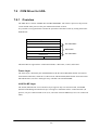
2.3.1 Display Unit
Hardware Configuration
LCD
Resolution
Tone
Method
VRAM
RAM for hardware window
FSTN semi-transparent liquid crystal display
192 x 384 dots
B/W 16 gray scales (4 gray scales are identifiable)
VGA compatible
512 KB
32 KB
Note:
With B/W liquid crystal displays the actual display colors will be changed to reverse video.
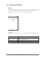
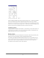
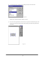
About the Display Screen
Since this terminal has a VGA controller, it can internally control the entire VGA (640 x 480 dots)
screen. However, only the 192 x 384 dots, which corresponds to the upper left portion of the VGA
screen, can be displayed.
Fig. 2.9
36
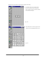
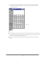
Software Functions
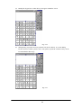
Standard Video BIOS is supported. This supports the following video modes:
Mode No
00h
01h
02h
03h
04h
05h
06h
07h
0Dh
0Eh
10h
11h
12h
Mode Type
Text
Text
Text
Text
Graphics
Graphics
Graphics
Text
Graphics
Graphics
Graphics
Graphics
Graphics
Characters
40 x 25
40 x 25
80 x 25
80 x 25
80 x 25
Resolution
320 x 200
320 x 200
640 x 200
640 x 200
320 x 200
320 x 200
640 x 200
640 x 350
320 x 200
640 x 200
640 x 350
640 x 480
640 x 480
Colors
16
16
16
16
4
4
2
2
16
16
16
2
16
Memory Segment
B800h
B800h
B800h
B800h
B800h
B800h
B800h
B000h
A000h
A000h
A000h
A000h
A000h
Hardware Window
The hardware window provides the superimpose function for the VGA controller.
With this hardware window a pop-up screen can be displayed without affecting the operation of
the application program. This hardware window is used in the keypad driver and various utility
programs.
Contrast Adjustment
The contrast of the liquid crystal display automatically compensates for temperature changes.
The user can adjust the offset value (refer to Chapter 6 “Keyboard Controller”) for the automatically
adjusted contrast in the following ways.
Press the 8 key after the Fn key to increase the contrast offset one step.
Press the 9 key after the Fn key to decrease the contrast offset one step.
Call the system library to increase/decrease the contrast offset.
37
2.3.2
EL Backlight
Overview
This terminal has the following functions to control the backlight. For more information refer to
Chapter 6 “Keyboard Controller”.
Manual Backlight ON/OFF function
Auto Backlight OFF function (ABO)
Auto Backlight Control function (ABC)
Manual Backlight ON/OFF Function
The backlight can be turned on and off with the following methods.
Press the 7 key after the Fn key to turn on or off the backlight.
Call the system library to turn on or off the backlight.
Auto Backlight OFF Function
This function automatically turns off the backlight when no key or touch panel input has been
occurred in the specified period of time. The time interval until the backlight is automatically turned
off can be set with the System Menu or the system library.
Auto Backlight Control Function
This function detects the intensity of ambient light and automatically turns on or off the backlight
accordingly. This function is set to off by default, however, it can be set to on using the System
Menu or system library. For more information about the system library refer to Chapter 8.6.2 “
System Library”.
38
2.3.3 Touch Panel
Hardware Configuration
Method
Resolution
: Analog type touch panel
: 192 x 384 dots
Software Function
To enable application programs to acquire touch panel coordinates, the following two pieces of
software are provided:
PENMOUSE.COM
With this PENMOUSE.COM application programs can acquire touch panel input through the
mouse I/F. (refer to Chapter 7.5 “PenMouse Driver”.)
KEYPAD.EXE
With this keypad driver application programs can perform character input through the touch
panel. However, it cannot be used concurrently with PENMOUSE.COM. (refer to Chapter 7.4
“Keypad Driver / Hardware Window Manager”.)
39
2.3.4 Disk
Types of Disk
Type
RAM disk
Basic drive
F-ROM disk
PC card
Drive name
A
C
D
G or F
Capacity
0 to 1920 Kbytes
768 Kbytes
0, 4, 8, 12, 16 or 24 Mbytes
SRAM card, ATA card
Note:
The drive name of the PC card varies for each model. For more information refer to Chapter 2.1.3
“Drive Configuration”.
RAM Disk
Part of the main RAM can be assigned on the RAM disk using System Menu.
The contents of the RAM disk will not be erased if the power switch is turned on and off, since they
are backed-up by the main battery and the sub-batteries. The contents of the RAM disk are not
affected by pressing the RESET switch either. Since this RAM disk permits the use of INT13h, it
can be used as the built-in fixed disk. Its drive name is A.
Note:
Since the RAM disk shares part of the main memory installed in the main unit, a large-RAM disk
size may affect the operation of application programs.
Basic Drive
Part of the DINOR FLASH ROM is used as the basic drive. It cannot be written to.
Disk capacity : 768 KB
Since the basic drive supports the INT13h (Read Only) interrupt, it can be used as the built-in fixed
drive. Its drive name is C.
40
F-ROM Drive
The F-ROM drive is supported as a disk for which both read and write operations are possible (only
for models with the F-ROM drive). Various disk capacities are supported for each model:
Disk capacity: 0 (models without F-ROM), 4M, 8M, 12M, 16M or 24 MB.
To format the F-ROM drive use the System Menu. For information about the formatting method
refer to Chapter 3 “System Menu”. In this process the System Menu will call TFORMAT.EXE from
drive (C:) to format the F-ROM drive.
For more information about the TFORMAT.EXE operation refer to Appendix A TFORMAT.
Since this F-ROM drive supports the INT13h interrupt, it can be used as the built-in fixed drive. Its
drive name is D.
PC Card Drive
If either an SRAM card or ATA F-ROM card is inserted in the PC card slot, it can be used as the
drive G (Drive F for models without the F-ROM drive). If the ATA F-ROM card is inserted in the
card slot, the system can boot up according to the CONFIG.SYS/AUTOEXEC.BAT files included
on this card. This start-up method is called "card boot".
For more information about card boot refer to Chapter 4.3 “Card Boot”.
41
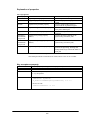
2.3.5 Serial Communication
Available Interfaces
Port
COM1
I/O Address
3F8h-3FFh
Name
8-pin serial I/F
COM2
2F8h-2FFh
COM3
3E8h-3EFh
Uses
Connection with a barcode
reader or PC
14-pin serial I/F Connection with an
expansion I/F device
IrDA 1.0
Communication with an I/O
Box or between two IT2000s
(Modem card)
Modem card
COM4
2E8h-2EFh
IrDA 1.1
Communication with an I/O
Box or between two IT2000s
Remark
Can be switched
via the system
library.
If a modem card is
used.
Direct control not
possible
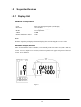
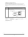
COM1
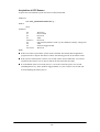
This is a COM port for RS-232C communication. This port can be used after turning on the power to
the 8-pin serial I/F via the system library. The 8-pin serial I/F is located on the side panel of the main
unit.
Pin assignment
Fig. 2.10
42
Pin 1.
Pin 2.
Pin 3.
Pin 4.
Pin 5.
Pin 6.
Pin 7.
Pin 8.
SD
RD
RS
CS
Vcc
GND
ER
DR
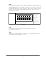
COM2
Either the 14-pin serial I/F or IrDA 1.0 can be assigned to this COM2 port depending on the system
library setup. Both the 14-pin serial I/F and IrDA 1.0 can be used as a normal RS-232C interface. By
default, the COM2 channel is not assigned to either device. Therefore, always use the system library
to designate either the 14-pin serial I/F or IrDA, then turn on the power. The 14-pin serial I/F is
located on the rear of the panel.
Pin assignment
8
9
10
11
12
13
14
1
2
3
4
5
6
7
Pin
Pin
Pin
Pin
Pin
Pin
Pin
Pin
Pin
Pin
Pin
Pin
Pin
Pin
1.
2.
3.
4.
5.
6.
7.
8.
9.
10.
11.
12.
13.
14.
GND
GND
N.C.
SD
RD
RS
ER
CS
CI
DR
CD
EXTSW
VH
VH
Fig. 2.11
COM3
A modem card, if one is inserted in the PC card slot, can be used as the COM3 port.
(refer to Chapter 2.3.6 “PC Card”.)
COM4
The COM4 port is dedicated for IrDA 1.1. It is used internally by the FLINK Utility. Therefore, it
cannot be directly controlled by application programs.
43
2.3.6
PC Card
Hardware Overview
Standard
Register compatibility
Slot
Power supply
Card lock switch
Conforms to PCMCIA Release 2.1
Has register compatibility with Intel 82365SL Step
1 slot TYPE II
Vcc : 5V (not operable at 3.3V)
Has a card lock switch
Recommended PC Cards
Type
SRAM card
ATA Flash ROM card
Model
DT-635MC (256 KB)
DT-636MC (512 KB)
DT-637MC ( 1 MB)
DT-9031FMC ( 2.5 MB)
DT-9032FMC ( 5 MB)
DT-9033FMC (10 MB)
DT-9034FMC (20 MB)
How to Format SRAM Card and ATA F-ROM Card
To format, call FORMAT.COM in the basic drive (C:). Then, in the DOS prompt screen that
appears, execute the following command to format the SRAM card or ATA F-ROM card.
FORMAT.COM can also be called as a child process.
FORMAT G:
COM Port of Modem Card
COM Port
IRQ
I/O Address
COM3
11
3E8h to 3EFh
Notes:
This port is not applicable for a 3.3V card, CardBus, or a ZV port.
Neither turn off the power nor remove the card while accessing the card. If this is done, system
operation becomes unstable.
Before using each type of PC card the PC card driver should be installed by means of the
CONFIG.SYS file. For information about the method used to write CONFIG.SYS refer to
Chapter 4.2 “How to Write CONFIG.SYS and AUTOEXEC.BAT”.
If the PC card is inserted in the slot and the card is locked, a card recognition sound (buzzer) will
be issued. Since the card is locked, a short period may be required until the recognition sound is
actually issued. Therefore, it is necessary to confirm this recognition sound in advance if
accessing to the card. An error may occur if the card is accessed before the recognition sound is
issued.
44
Card Lock Switch
The IT-2000 has a card lock switch to prevent accidental removal of the card. Any card can be made
usable only after it has been inserted in the slot and the switch has been locked properly. However,
since some types of cards do not allow this card lock switch to be closed, a library routine to disable
this switch is supported. For more information refer to Chapter 8.6.2 "System Library”.
45
2.3.7
Clock Timer
Clock BIOS
00h to 07h of the INT1Ah function is compatible with the IBM PC/AT.
Since INT1Ah can be called in the C language, an alarm operation using the clock can be set with
the system library.
Alarm
If an alarm operation is set using the INT1Ah or system library, it is possible to cause an INT4Ah
interrupt at the specified time to issue the alarm. Normally a buzzer sounds if an INT4Ah occurs,
however, the application program side can hook this interrupt and perform its unique alarm process.
It is also possible to automatically turn on the power at the specified alarm time by means of the
system library (refer to Chapter 8.6.2 “System Library”).
46
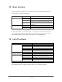
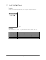
2.3.8
Buzzer
This terminal is provided with a buzzer function that is compatible, via an appropriate interface, with
the IBM PC. The application side can sound this buzzer by controlling the I/O port assigned to 61h.
It is also possible to modify the sound frequency by controlling channel 2 of the timer.
For information about the method used to modify the frequency refer to the hardware manual of the
PC/AT compatible machine.
Use of Buzzer From the System
The IT-2000 system uses the buzzer in the following cases:
At power on (boot).
If the power is turned off by the Power switch.
If the PC card is inserted/removed.
If a key input is accepted (for matrix key and keypad). Enable/disable can be set with the system
library. (refer to Chapter 8.6.2 “System Library”)
If the key buffer is full.
At a low battery voltage (LB1).
If an alarm interrupt (INT4Ah) occurs.
When the battery lid is opened while the power is on.
At a hardware anomaly.
For calibration and System Menu operation.
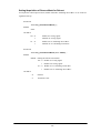
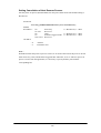
Setting Volume of Buzzer
The buzzer volume can be set with System Menu or from the system library.
The volume can be set to one of the four levels: OFF/Small/Medium/Large.
For more information about System Menu and the system library refer to Chapter 3 “System Menu"
and Chapter 8.6.2 “System Library” respectively.
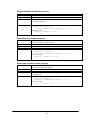
47
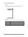
2.3.9
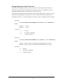
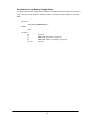
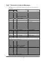
Barcode Reader
Overview
The IT-2000 supports the following two Casio OBR (Optical Barcode Reader) models:
DT-9650BCR ( Pen scanner )
DT-9656BCR ( CCD scanner)
Connect the OBR to the COM1 (8-pin) port of this terminal, and set up the interface as follows.
Synchronization
Baud rate
Data bit
Parity bit
Stop bit
Asynchronous
9600 bps
8 bits
none
1 bit
For communication between the OBR and this terminal use the OBR library. The various settings
such as an objective readout codes can be set up by transmitting the set up commands from this
terminal to the OBR.
Notes:
The OBR power is controlled by the OBR library function.
Before connecting the OBR to this terminal, turn off the main power.
Every OBR can write the current setup values in the EEPROM built into each OBR.
This ensures that the setup data is retained even when the power is off.
For more information about the OBR library, refer to Chapter 8.6.4 “OBR Library”.
48
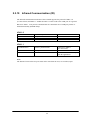
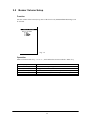
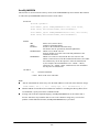
2.3.10
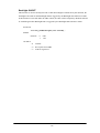
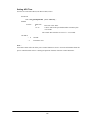
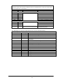
Infrared Communication (IR)
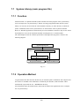
The infrared communication function of this terminal supports the protocol of IrDA 1.0
(see note below) and IrDA 1.1 standards. IrDA 1.0 can be used as the COM port for a general
RS-232C. IrDA 1.1 can provide communication at a maximum rate of 4 Mbps by means of
the dedicated utility (FLINK utility).
IrDA 1.0
Item
Synchronization
Baud Rate
COM Port
Specification
Asynchronous
115.2 Kbps max.
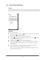
COM2
Remark
Conforms to IrDA1.0
Synchronization
Frame synchronization
Conforms to IrDA1.1
(see note below)
Baud Rate
COM Port
4 Mbps max.
COM4
IrDA 1.1
Cannot be controlled directly
from the application.
Note:
The distance between the two ports must not be more than 60 cm (or 23.6 inches) apart.
49
2.3.11 Keys
Hardware Overview
Key configuration
IRQ
Key repeat function
Simultaneous pressing of multiple keys
Roll-over function
5 (column) x 3 (row) keys
IRQ1
available
not available
not available
Key Layout
See the following key layout.
Fn
7
8
9
-
4
5
6
CLR
0
1
2
3
Fig. 2.12
Fn key
The "Fn" key should be used in combination with the numeric key. Hold down the "Fn" key and
press a numeric key.
Fn ->
Fn ->
Fn ->
Fn ->
Fn ->
0
1 to 6
7
8
9
Function key F10
Function key F1 to F6
Backlight on/off
Increase the contrast
Decrease the contrast
For more information refer to Chapter 6 “Keyboard Controller”.
50
2.3.12
Sensors
The IT-2000 has the following three types of built-in sensors:
Illumination
sensor
Temperature
sensor
Battery voltage
level sensor
Attached to the upper section of this terminal and used to sense the ambient
light intensity. It is used for the Auto Backlight Control (ABC) function. It
cannot be controlled directly from the application.
(For more information about the system library refer to Chapter 6 “Keyboard
Controller”.)
Attached to the inside of the main unit and used to detect the ambient
temperature. It is used for Automatic Brightness Adjustment (ABA) of the
liquid crystal display. It cannot be controlled directly from the application.
(For more information about the system library refer to Chapter 6 “Keyboard
Controller”.)
Detects the voltage levels of the main battery, sub-batteries, and card
battery. It is used by the system to take action against low battery voltges. The
system manages low voltage through this battery electric potential sensor.
Applications can acquire the information from this battery voltage level sensor
via the system library or APM BIOS.
(Refer to Chapter 2.2.4 “Battery Voltage Monitoring Process”.)
51
3.
3.1
System Menu
Overview
The system menu is a program and used to perform various setups (system clock, contrast of
liquid crystal display, etc.) and implement (downloading) application programs, all of which
are necessary to use this terminal.
To start up the system menu press the reset switch located at the back of the main unit.
When the reset switch is released a short beep will sound and, after a short while, a screen as
shown in Fig. 3.1 will appear.
The calibration (touch panel adjustment) program is initiated first and it must be executed
before entering to the system menu selection stage. If this terminal is used for the first time or
if the touch screen is out of line, adjust the touch panel using this calibration program.
(For information about adjusting the touch panel refer to Chapter 3.9 “Touch Panel Calibration”)
If the “ 1” key is pressed the system menu will be initiated as shown in Fig. 3.2.
Fig. 3.1
Fig. 3.2
52
3.2
Basic Operation
In the system menu a common set of key operations are used. The following list shows the
keys that can be used in the system menu.
Current Condition
Line cursor is on
Key Operation
8
2
CLR
RET
Others
0 to 9
RET
CLR
Operation Process
Moves the line selection cursor up one line.
Moves the line selection cursor down one line.
Moves the line selection cursor to the upper
menu area, if it is located in the lower menu area.
Confirms and executes the currently selected
menu item.
Selection of an item or entry of a numeric value.
Confirms the currently selected execution item.
Cancels the currently selected execution item.
If "FILE TRANSFER" or "MAINTENANCE" is selected for the first time after the system
menu is initiated, the operator is required to enter a password for system security purposes.
For information about password entry refer to Chapter 3.17 “Password Entry".
3.3
List of Functions
Command Screen
SYSTEM SETUP
Key Click Sound
Buzzer Volume
LCD Contrast
Auto Backlight
Auto Power OFF
Calibration
FILE TRANSFER
Ymodem Batch
(requires password)
FLINK (IrDA)
MAINTENANCE
Set Date/Time
(requires password) MS-DOS Command
RAM Disk Size
Format Disk
Default Setting
EXIT (power off)
Description
Switch ON or OFF the key click sound.
Set volume of buzzer.
Adjust the brightness of contrast.
Set the control of auto backlight.
Set auto power off.
Adjust the calibration on touch panel.
Start up the YMODEM utility.
Start up the FLINK utility.
Set date and time.
Set the command entry mode.
Change the size of RAM DISK.
Format on user disk.
Start up the system initialization.
For information about each function in the list above refer to the following pages.
53
3.4
Key Click Sound Setup
Function
Sets the key click sound ON and OFF. If it is set to ON, a key click sound is heard when a key
is pressed or when the keypad is touched. It does not sound if it is set to OFF.
Fig. 3.3
Operation
Select ON/OFF with the “ 0” or “ 1 “ key, then confirm the selection with the “RET” key.
Key Operation
0 key
1 key
. (decimal) key
RET key
CLR key
Others
Function
Sets the key click sound to OFF.
Sets the key click sound to ON.
Toggles to ON and OFF of the key click sound.
Confirms the current setup and exits the current operation.
Cancels the setup and exits the current operation.
Invalid.
54
3.5
Buzzer Volume Setup
Function
Sets the volume of the buzzer (beep). One of the four levels (OFF/Small/Medium/Large) can
be selected.
Fig. 3.4
Operation
Make a selection with a key, “ 0” to “ 3 “, and confirm the selection with the “ RET” key.
Key Operation
0 to 3 keys
. (decimal) key
RET key
CLR key
Others
Function
Selects the corresponding number.
Toggles between two selections.
Confirms the currently selected setup and exits this operation.
Cancels the currently selected setup and exits this operation.
Invalid.
55
3.6
Contrast Adjustment
Function
Adjusts the contrast of the liquid crystal display.
Fig. 3.5
Operation
Press the “8 “ key to increase the contrast or press the “ 2” key to decrease the contrast.
Press the “ RET” key to confirm the setting.
Key Operation
8 key
2 key
RET key
CLR key
Others
Function
Increase the contrast.
Decrease the contrast.
Confirms the currently selected contrast setup and exits this
operation.
Cancels the currently selected contrast setup.
Invalid.
Note:
Depending on whether the parameters are being modified, the CLR key activates differently.
For example, if the CLR key is pressed while a parameter is being changed, that parameter
will be reset to the previous value.
However, if the CLR key is pressed while no parameter is being changed, the setup process will
be aborted and exited at that point.
56
3.7
Auto Backlight Setup
Function
Sets the auto backlight control ON or OFF (refer to Chapter 6 “Keyboard Controller").
Fig. 3.6
Operation
Select ON/OFF with the “ 0” or “ 1” key, then confirm the selection with the “RET” key.
Key Operation
0 key
1 key
. (decimal) key
RET key
CLR key
Others
Function
Turns the auto backlight control to OFF.
Sets the auto backlight control to ON.
Toggles to ON and OFF of the auto backlight control.
Confirms the current setup and exits this operation.
Cancels the current setup and exits this operation.
Invalid.
57
3.8
Auto Power OFF Setup
Function
Sets the time-out period of the auto power off function (APO) (refer to Chapter 2.2.3 “Power OFF
Process"). This time-out period is the interval between when no key entry or no entry on the
touch panel is made and when the power of system is shut off automatically.
Fig.3.7
Operation
Set the APO time out period with the “ 2” or “ 8 “ key, then confirms the setting with the “ RET”
key.
Key Operation
8 key
2 key
RET key
CLR key
Others
Function
Increase the APO timeout period.
Decrease the APO timeout period. If "DISABLE" appears,
the APO function is disabled.
Confirms the current setup and exits this operation.
Cancels the current setup and exits this operation.
Invalid.
58
3.9
Touch Panel Calibration
Function
Adjusts the calibration of touch panel. If an inconsistency is noted between the target position and
the position actually touched on the touch panel, correct it by performing this calibration adjustment.
Fig. 3.8
Operation
Adjustment of the calibration :
with the stylus provided.
the center of this
in the upper left corner of the screen, then touch
First make sure that the arrow points to
When the buzzer sounds, release the stylus from the touch panel.
After the
in the upper left corner disappears and the arrow moves to the
in the upper
right corner, touch it in the same way.
Do the same for the
When all four
s in the lower left and lower right corners.
s are touched by the stylus, the touch panel calibration is completed.
If any improper operation has been done, press the “1” key to perform the touch panel
calibration again.
If the “2” key is pressed after the four positions have been touched, the calibration
adjustment result takes effect and the menu screen is restored.
If the “ 2 “ key is pressed before finishing on the fourth position, the adjustment process
performed so far will be canceled.
59
Note:
If an
mark does not disappear and the arrow does not move to the next position even if the
mark has been touched by the stylus, an incorrect position was likely touched.
Touch the correct position.
Key Operation
1 key
2 key
Others
Function
Adjusts the touch panel calibration starting from the beginning.
Returns to the menu screen.
Invalid
60
3.10
YMODEM Utility
Function
Used to achieve a file transfer via the COM cable.
Communication can be established either between an AT-compatible machine (PC) and an
IT-2000 (main unit), referred to as "PC-to-HT communication". A dedicated 9-pin DSUB-8-pin
cross-type cable (DT-9689AX) is required to connect both the terminals. This utility does not have
functions to allow communication between HT and HT. Use the FLINK function for the HT-to-HT
communication.
Fig. 3.9
Fig. 3.10
Fig. 3.11
61
Note:
When the cable comes off while the communication takes place:
If the connection cable is accidentally unplugged while communication between the IT-2000 and
PC is taking place, a communication error results and communication is interrupted. In this case
the communication software on the PC will display an error message and interrupt
transmission/reception, however, some data may remain in the transmission buffer. If an attempt
is made to restart communication in this condition, the XY utility may receive illegal packets,
hampering normal communication. If this occurs, terminate the communication software on the
PC side then restart it to restore normal communication.
About time stamping of files:
This utility supports the function to exchange time stamp information between the transmitted file
and received file. The time stamp information to be exchanged will be processed assuming that it
is Greenwich standard time. In contrast, the time used by the IT-2000 is the local time, and the
time stamp of IT-2000 files are accordingly controlled based on the local time.
The XY utility, for file transmission/reception by means of the YMODEM protocol, will convert
a time stamp in Greenwich standard time to a time stamp in local time, or vice versa. This time
conversion is achieved according to the environment variable, TZ. In communication between
two IT-2000 terminals, if, for example, TZ of the transmission side is "JST+5", the time stamp of
a file to be transmitted will have five hours added. In this case the reception side will create a file
by subtracting five hours from the time stamp of the received file.If the environment variable TZ
is not set, this time conversion is not performed.
The time stamp made at XMODEM communication uses the system time of the reception side.
Transmission side
IT-2000(TZ=none)
IT-2000(TZ=GMT)
IT-2000(TZ=JST+5)
IT-2000(TZ=JST+5)
PC
0
0
+5
+5
12:00 ?
12:00 12:00
12:00
12:00
12:00 0 12:00
12:00 0 12:00
17:00 -5 12:00
17:00 ? ??:??
??:?? -5 (??-5):??
Reception side
IT-2000(TZ=none)
IT-2000(TZ=GMT)
IT2000(TZ=JST+5)
PC
IT2000(TZ=JST+5)
About key input during communication
Do not press any key during communication, otherwise file transmission/reception may be
hampered.
62
Operations
(1) SEND FILE TO HT (one file transmission from IT-2000 to IT-2000)
This function may be available in future (as of now, not available). It is not allowed to use the
function. If the file transmission between IT-2000s is needed, FLINK utility may be used (refer to
Chapter 3.11 “FLINK Command”.).
(2) SEND FILE TO PC (one file transmission from IT-2000 to PC)
This function is used to copy an optional file from an IT-2000 to PC. To do this, use
commercial terminal emulation software on the PC side. The destination directory of this
copy should be specified by the terminal emulation software on the PC side.
Connect one end of the serial cable (cross-type) to the 8-pin COM port of the IT-2000 and
connect the other end to the COM port of the PC.
Select "SEND FILE TO PC" on the transmission side.
On the PC side initiate the terminal emulation software to prepare for download.
Select a baud rate of 9600 bps, and specify the YMODEM Batch protocol.
When the file name input screen appears on the IT-2000 side, specify the transmitted file with
its full path name (including the drive name), then press the “RET” key.
Pressing the “RET” key starts file transfer. When the "Normal End" message is displayed, file
transmission has been completed.
If the “CLR” key is pressed during file transfer, transfer will be interrupted. It will take about
10 seconds for communication to completely stop.
(3) SEND ALL TO HT (transfer all files in the user drive of IT-2000 to IT-2000)
This function may be available in future (right now, not available). It is not allowed to use the
function. If the file transmission between IT-2000s is needed, FLINK utility may be used (refer to
Chapter 3.11 “FLINK Command”.).
(4)
RECEIVE FILES (file reception)
The function is used to receive one file from the PC. On the PC side commercial terminal emulation
software can be used. In this operation the copy destination directory cannot be specified.
Connect one end of the serial cable (cross-type) to the 8-pin COM port of the IT-2000 and
connect the other end to the COM port of the PC.
Move the cursor to " RECEIVE FILES ", then press the “ RET” key to prepare for reception.
Start upload with the terminal emulation software on the PC side.
Select a baud rate of 9600 bps, and specify the YMODEM Batch protocol.
63
When the "Normal End" message is displayed on the IT-2000 side, file reception has been
completed. For information about the copy destination directory refer to the following table.
If the “CLR” key is pressed during communication, file reception will be interrupted. It will
take about 10 seconds for communication to completely stop.
The following table shows the possible destination drive/directory for copy purposes.
FROM drive (D:)
Installed
RAM disk (A:)
Installed
Not installed
64
Copy destination drive/directory
FROM drive (D:)
FROM drive (D:)
3.11
FLINK Command
Function
Files can be transferred by infrared communication (IR). This can be implemented either as PC-toHT (AT-compatible machine to IT-2000) communication or as HT-to-HT (between two IT-2000
terminals) communication.
To perform PC-to-HT communication an I/O Box for IT-2000 and a PC-side communication utility
"LMWIN.EXE" is required.
Fig. 3.13
Fig. 3.12
Fig.3.14
65
Note:
If the identical file name exists on the reception side, this command overwrites the existing file.
At this time, the system does not unconditionally overwrite the existing file but creates a temporary
file on the reception-side disk and attempts the overwrite after file transmission has been competed.
This protects file data even if transmission of the file fails.
Therefore, if the identical file name exists on the reception side, the reception-side disk must have a
space large enough for the transmitted file. If there is insufficient space, either delete unnecessary
files in advance on the reception side or use the file delete command (on page 253) to delete them.
Operation
SEND FILE to HT (One file transmission from IT-2000 to IT-2000)
This function is used to copy one file from one IT-2000 to another IT-2000. This file will be copied
to a destination directory that has a name that is identical to the source directory.
Place the two IT-2000 units so that their IR windows face each other.
Select "SEND FILE TO HT" at the transmission side.
Select "REMOTE SERVER" at the reception side to prepare for reception.
If the file name input screen appears at the transmission side, specify the transmitted file by its
full pathname (including the drive name), then press the “ RET” key.
Press the ”RET” key to start file transfer. If the "Normal End" message is displayed, file
transmission has been completed.
Note:
If the “CLR” key is pressed during file transfer, transfer will be interrupted. It will take about 10
seconds for communication to completely stop.
SEND ALL to HT (Transfer of all files in the F-ROM drive of IT-2000 to IT-2000)
This function is used to mirror-copy the F-ROM drive. All files existing on the F-ROM drive of the
copy source side are copied to the F-ROM drive of the destination side. Since this process does not
attempt either file deletion or formatting on the copy destination side, it is necessary to confirm in
advance that the F-ROM drive of the destination side has sufficient free space.
Place the two IT-2000 units so that their IrDA interface windows face each other.
Select "REMOTE SERVER" on the reception side to prepare for reception.
On the transmission side move the cursor to "SEND ALL TO HT" and press the “ RET” key.
File transfer begins.
If the "Normal End" message is displayed, file transmission has been completed.
66
Note:
If the “CLR” key is pressed during file transfer, transfer will be interrupted. It will take about 10
seconds for communication to completely stop.
REMOTE SERVER (remote server mode )
The remote server mode is used by the system which assigns the right of issuing a transmission
request to the partner side and enters the wait state for a request from the partner.
To facilitate communication between two IT-2000 terminals, set the reception side to this mode.
For HT-to-PC communication set the IT-2000 side to this mode and perform the entire operation on
the PC side.
Move the cursor to "REMOTE SERVER" and press the “ RET” key.
If the "Hit Any Key!" message appears, file transmission has been completed.
Note:
If the “CLR” key is pressed during file transfer, transfer will be interrupted. It will take about 10
seconds for communication to completely stop.
About communication with PC
To achieve communication between a PC and IT-2000 it is necessary to prepare an I/O Box for
IT-2000 and PC-side communication utility "LMWIN.EXE (Windows version)". The following
procedure shows the steps required for communication with a PC.
Connect the I/O Box and PC using a communication cable. Turn on the power of I/O Box.
Mount the IT-2000 on the I/O Box.
Select "REMOTE SERVER" on the IT-2000 side to enter the wait state.
On the PC side initiate the PC-side communication utility, LMWIN.EXE.
Operate the PC-side communication utility to perform reception or transmission. For information
about the operation of the PC-side communication utility refer to the "IT-2000 Upload/Download
Utility Manual" available separately.
If the "Hit Any Key!" message appears on the IT-2000 side, file transmission has been
completed.
Note:
If the “CLR” key is pressed during file transfer, the transfer will be interrupted. It will take about 10
seconds for communication to completely stop.
67
3.12
System Date/Time Setup
Function
This is used to set (modify) the date and time of the built-in timer in the IT-2000 unit.
Fig. 3.15
Operation
Enter in the following order: year -> month -> day -> hour -> minute. Press a numeric key and the
corresponding number will appear in the cursor position. Press the “ RET” key to advance to the
next setting. If the “RET” key is pressed without making a numeric entry, the cursor will advance to
the next setting without affecting the previous value. If the “ RET” key is pressed when the cursor is
positioned on the minute setting, the current setup is confirmed.
Note that the seconds can not be specifically set. When the date and time is modified, the seconds
will be set to 0. The year can be set to between 1980 and 2099. If the entered value includes an
invalid number, the setup operation will result in an error when the entire entry has been completed.
If this occurs, reenter from the beginning.
Key Operation
0 to 9 keys
RET key
CLR key
Others
Function
Enters the corresponding digit in the cursor position.
Moves to the next input item. When the cursor is in the minute
setting, the current setup is confirmed.
Cancels the currently selected setting and exits this operation.
Invalid.
Operations on the touch panel are not permitted.
68
3.13
Command Prompt
Function
This is the MS DOS command prompt screen. An appropriate DOS command can be inputted
through the keypad.
This DOS command prompt is the result of calling COMMAND.COM as a child process from the
system menu. Consequently, if the EXIT command is entered, operation returns to the system menu.
Fig. 3.16
69
3.14
RAM Disk Size Change
Function
This screen is used to set the RAM DISK size (capacity). The setting will become valid after the
system has rebooted.
Fig. 3.17
Operation
Setting up the RAM disk
Adjust the RAM disk size with the “8” and “2” keys.
Confirm the setup with the “ RET” key.
When the "Hit Any Key... " message is displayed, press any key other than the “Fn” key.
The IT-2000 is turned off. After making sure that it turns off, press the reset switch on the
IT-2000 again.
After the IT-2000 is turned on again, the format confirmation screen, as shown below, will be
displayed during system start-up. Then press the “1” key. This properly formats the RAM disk.
After formatting the RAM disk is usable.
RamDisk is broken.
Format?
YES:1/NO:0
70
Key Operation
8 key
2 key
RET key
CLR key
1 key
0 key
Others
Function
Increases the RAM disk size.
Decreases the RAM disk size.
Confirms the currently selected RAM disk size and exits this
operation.
Cancels the currently selected RAM disk size.
Formats the RAM disk (Format confirmation screen).
Aborts formatting of the RAM disk.
Invalid.
Operations with the touch panel are not permitted.
71
3.15
Disk Format
Function
Formats the RAM disk and F-ROM drive.
Fig. 3.18
Operation
In the screen shown above, use the “2” or “8” key to select whether the RAM disk or user drive is to
be formatted, then press the “RET” key. This makes the following screen appear. In this screen press
the “1” key to move the cursor onto "YES" and press the “RET” key to start formatting. If either the
“RET” key is pressed while the cursor is on “NO”, or “CLR” key is pressed while the cursor is on
“YES”, the formatting operation will be canceled.
Fig. 3.19
Fig. 3.20
72
Key Operation
2 or 8 key
0 key
1 key
. (decimal) key
RET key
CLR key
Others
Function
Selects the objective item (drive selection screen).
Does not perform formatting (formatting start screen).
Starts formatting (formatting start screen).
Toggles YES and NO options of formatting.
Confirms the current setting.
Cancels the current setting.
Invalid.
73
3.16
System Initialization
Function
Sets all the system setups to their default settings.
Fig. 3.21
Operation
The following table shows the available key operations.
Key Operation
0 key
1 key
. (decimal) key
RET key
CLR key
Others
Function
Does not initialize the system.
Initializes the system.
Toggles YES and NO options of initialization.
Confirms the current setting.
Cancels the current setting and exits this operation.
Invalid.
74
3.17
Password Entry
Function
When "FILE TRANSFER" or "MAINTENANCE" is selected for the first time after the system
menu is initiated, the operator is requested to enter a password.
Fig. 3.22
Operation
With the keypad enter "system" (lowercase letter), then press the “RET” key. If the “CLR” key is
pressed without entering a character, the password entry operation will be canceled. If the “CLR”
key is pressed with characters having been entered, the characters entered so far will be canceled,
and the password entry operation must be performed again.
This password will, if it is accepted once, be valid and will not have to be entered again unless the
system menu is re-started.
Key
RET key
CLR key
Others
Touch Panel
BS key
Arrow key
INS key
DEL key
SP key
Others
Function
Confirms the entry.
Either clears or cancels the entered characters.
Inputted as a character comprising the password.
Function
Clears one character entered.
Invalid.
Inputted as a character comprising the password.
75
4.
MS-DOS
4.1
Overview
In general, if a personal computer is booted-up with a floppy disk in the drive, first an attempt will
be made to read MS-DOS from the floppy disk, and if a copy of MS-DOS does not reside on the
floppy it is loaded from the hard disk (C:).
However, this method cannot be used on this terminal since its basic drive (C:), which corresponds
to the hard disk of a PC, is defined as a read-only device. The MS-DOS on the boot drive (C:) can
be loaded initially provided that no PC card is inserted in the slot, but, in this case, it is not possible
to add the start-up code for user programs to the AUTOEXEC.BAT file. This problem is solved on
the terminal as follows.
At boot-up this terminal searches each drive to locate the CONFIG.SYS and AUTOEXEC.BAT
files and sets it as the current drive, then MS-DOS is loaded into the main memory. As a result,
the CONFIG.SYS and AUTOEXEC.BAT files in the current drive can be processed through
MS-DOS.
The CONFIG.SYS and AUTOEXEC.BAT files will be searched in the following order:
PC card drive ->
RAM disk ->
F-ROM drive ->
Basic drive
The CONFIG.SYS and AUTOEXEC.BAT files on the basic drive will be executed only if the
RESET switch is pressed. As a result, the System Menu, which is the maintenance program for
this terminal, will be initiated.
Since the main part of MS-DOS is always loaded from the basic drive (C:) in this case, it is not
necessary to install MS-DOS and COMMAND.COM on the user drive.
LOADING MS-DOS
Fig. 4.1
YES
RESET BUTTON
was pressed?
Specifies the basic drive as the current
drive.
NO
Specifies the drive on which CONFIG.SYS and
AUTOEXEC.BAT reside as the current drive.
Load MS-DOS.
Executes CONFIG.SYS and
AUTOEXEC.BAT in the current drive.
76
As described above, if the system power is turned on without an application installed (i.e. the
conditions just after purchase), the CONFIG.SYS and AUTOEXEC.BAT files locating on the basic
drive will be executed automatically. This inevitably initiates the System Menu (maintenance
program). Therefore, if not only CONFIG.SYS and AUTOEXEC.BAT, but also an application
program are installed on the user drive, it is possible for the application program to be automatically
initiated from the user drive.
Example 1
In the following example MS-DOS is loaded from the RAM disk which has been designated as the
current drive, since the system finds the CONFIG.SYS and AUTOEXEC.BAT first in the RAM
disk.
ATA CARD
RAM DISK
F-ROM
Basic Drive
NO CARD
CONFIG.SYS
AUTOEXEC.BAT
APPLICATION
CONFIG.SYS
AUTOEXEC.BAT
APPLICATION
CONFIG.SYS
AUTOEXEC.BAT
APPLICATION
Fig. 4.2
Example 2
In the following example the RAM disk contains only CONFIG.SYS. As a result, MS-DOS is
loaded from the F-ROM drive designated as the current drive.
ATA CARD
RAM DISK
F-ROM
Basic Drive
NO CARD
CONFIG.SYS
APPLICATION
CONFIG.SYS
AUTOEXEC.BAT
APPLICATION
CONFIG.SYS
AUTOEXEC.BAT
APPLICATION
Fig. 4.3
Example 3
The following example shows a case where there is no F-ROM drive. The search order is also the
same in this case. However in this case, CONFIG.SYS and AUTOEXEC.BAT in the basic drive
will be executed, and System Menu will be initiated.
NO CARD
CONFIG.SYS
APPLICATION
CONFIG.SYS
AUTOEXEC.BAT
APPLICATION
Fig. 4.4
77
4.2
How to Write CONFIG.SYS and AUTOEXEC.BAT
This section explains how to write the CONFIG.SYS and AUTOEXEC.BAT files mentioned in the
previous section. A basic explanation of the CONFIG.SYS and AUTOEXEC.BAT is not given here.
For further information about these files refer to the MS-DOS manual or appropriate technical
documents. Observe the following notes when writing a CONFIG.SYS file.
The System Driver (SYSDRV.SYS) is required to operate this terminal. Always include a line
through which to load the System Driver in the CONFIG.SYS.
As described above, MS-DOS, which is in the basic drive, is always loaded. Consequently,
C: COMMAND.COM is used as the command interpreter. Therefore, set a path to
COMMAND.COM to be reloaded in CONFIG.SYS using the SHELL command.
Within CONFIG.SYS the MENU command can be used. Note however, that no power off
command is included in the MENU selection screen. This is to prevent the power from being
accidentally turned off while loading the drivers. The Power switch is also disabled until the
CASIOAPM.COM program is initiated from AUTOEXEC.BAT, etc. In other words, the MENU
command should only be used in the application program development processes.
Example of CONFIG.SYS
The following example shows a typical CONFIG.SYS file script. Since this example assumes that
the system is booted from either the RAM disk or NAND F-ROM drive, it is necessary to partially
modify it if booting up from the ATA card.
For information about booting from the ATA card refer to Chapter 4.3 "Card Boot".
1
FILES=30
Not required
2
BUFFERS=20
Not required
3
DOS=HIGH, NOUMB
Required (1)
DEVICE=C:
Required (2)
4
5
6
7
8
9
10
11
12
13
14
15
16
17
18
SYSDRV.SYS
DEVICE=C:HIMEM.SYS /M:2
DEVICE=C:POWER.EXE
DEVICE=C:TIME.SYS
DEVICE=C:EMM386.EXE FRAME=C800 X=C000-C7FF X=D800-DFFF I=C800-D7FF
SHELL=C:COMMAND.COM C: /P /E:1024
DEVICE=C:CARDSOFTSS365SL.EXE /SKT=1
DEVICE=C:CARDSOFTCS.EXE /POLL:1
DEVICE=C:CARDSOFTCSALLOC.EXE
DEVICE=C:CARDSOFTATADRV.EXE /S:1
DEVICE=C:CARDSOFTMTSRAM.EXE
DEVICE=C:CARDSOFTMTDDRV.EXE
DEVICE-C:CARDSOFTMTDAPM.SYS
DEVICE=C:CARDSOFTCARDID.EXE
INSTALL=C:CARDSOFTCS_APM.EXE
78
Required (3)
Required (4)
Required (4)
Required (5)
Required
Required (6)
Required (6)
Required (6)
Required (6)
Required (6)
Required (6)
Required (6)
Required (6)
Required (6)
(1)
DOS=HIGH,NOUMB
This specifies that the main part of DOS is to be loaded in the HMA and, consequently, the
UMB (Upper Memory Block) is not used. This terminal does not support a memory space for
UMB if the EMS memory is to be used. Therefore, always specify NOUMB when using the
EMS.
(2)
DEVICE=C:
SYSDRV.SYS
This driver is required to operate this terminal. Always install it before all other drivers.
(3)
DEVICE=C:
HIMEM.SYS /M:2
Never fail to specify the "/M:2" option.
(4)
POWER.EXE
DEVICE=C:TIME.SYS
DEVICE=C:
This driver is required to enable the APM function. TIME.SYS must follow immediately after
POWER.EXE.
(5)
DEVICE=C:
EMM386. EXE FRAME=C800 X=C000-C7FF X=D800-DFFF I=C800-D7FF
Always specify the above options if using the EMS. Options other than the X option can be
eliminated if the EMS is not used.
(6)
CARDSOFTSS365SL.EXE /SKT=1
DEVICE=C:CARDSOFTCS.EXE /POLL:1
DEVICE=C:CARDSOFTCSALLOC.EXE
DEVICE=C:CARDSOFTATADRV.EXE /S:1
DEVICE=C:CARDSOFTMTSRAM.EXE
DEVICE=C:CARDSOFTMTDDRV.EXE
DEVICE=C:CARDSOFTMTDAPM.SYS
DEVICE=C:CARDSOFTCARDID.EXE
INSTALL=C:CARDSOFTCS_APM.EXE
DEVICE=C:
This driver is required if the PC card driver is used. However, if the SRAM card is not used, the
lines following ATADRV.EXE can be modified as follows. This saves a memory space as large as
that used for the SRAM card driver. For more information refer to Appendix B "PC Card Driver".
CARDSOFTATADRV.EXE /D:1
DEVICE=C:CARDSOFTMTDAPM.SYS
DEVICE=C:CARDSOFTCARDID.EXE
INSTALL=C:CARDSOFTCS_APM.EXE
DEVICE=C:
79
Example of AUTOEXEC.BAT
The following example shows a typical AUTOEXEC.BAT script. Since this example assumes that
the system is booted from either the RAM disk or the NAND F-ROM drive, it is necessary to
partially modify it if booting up from the ATA card.
For information about booting from the ATA card refer to Chapter 4.3 "Card Boot".
1: C: ENDATA
2: C: CASIOAPM
3: (Environment variables setup and application call, etc.)
Note:
(1)
C:
Required (1)
Required (2)
Optional
ENDATA
Disables the card boot function in the BIOS. For more information refer to Chapter 4.3, "Card
Boot".
(2)
C:
CASIOAPM
Enables the touch panel and power switch operations. The touch panel and power switch
operations cannot be used until this program has been executed. This program only needs to be
called once when booting the system.
80
4.3
Card Boot
Basically the "card boot" operation boots MS-DOS from the ATA card, just like it is booted from a
floppy disk. For this terminal the boot operation looks the same as this case. However, this terminal
uses a boot process greatly different from a general card boot so that the MS-DOS in the drive C is
always loaded, in such a way that MS-DOS not residing in the card is booted.
Usually, in order to access the ATA card, a specific card driver is required. This card driver should
be registered as an MS-DOS block device for the MS-DOS and added as a new drive to the system.
Then the user can read from and write to the disk via the added drive by this device driver.
BIOS
Physical
Drive
MS-DOS
Application
CARD
Driver
ATA CARD
G
Fig. 4.5
However, in order to achieve a card boot, readout from the ATA card must be enabled before
MS-DOS is loaded into the main memory. To solve this conflict the terminal has a function in its
BIOS that can directly read the data from the ATA card. This function is assigned to the drive F (
drive E for models without an F-ROM) and the ATA card looks, from MS-DOS, like a physical
drive. As a result, when BIOS recognizes the presence of an ATA card during the boot process,
it will search for CONFIG.SYS and AUTOEXEC.BAT in the ATA card prior to loading MS-DOS.
If these files are found, the BIOS will load MS-DOS into main memory and shift control to
MS-DOS after designating the drive F as the current drive. Subsequently, MS-DOS will execute the
CONFIG.SYS and AUTOEXEC.BAT files in the current drive (drive F). This completes the load
process.
The mechanism determining which drive is specified as the one to be used by an application that
accesses the card is explained below. The drive G (drive F for models without F-ROM), which is a
drive specifically reserved for applications, will be enabled by CARDID.EXE which is loaded into
the main memory. It is loaded when CARDID.EXE is loaded and when both the drive F and drive G
are being enabled. If this is the case, note that if an attempt is made to access the drive F,
81
the drive G, which is currently enabled, will be disabled.
This problem arises from the fact that the hardware conditions established by initialization with
CARDID.EXE are lost since access to the drive F was executed by means of specific codes
included in the BIOS. To avoid this problem, these specific codes in BIOS should be disabled.
ENDATA.COM is used to do this. If ENDATA.COM is executed with the two drives mentioned
above enabled, the specific codes (program) in BIOS are disabled, and the drive G can be retained
as the only valid card drive. Below are example CONFIG.SYS and AUTOEXEC.BAT scripts
used to boot a card.
Example of CONFIG.SYS
FILES=30
BUFFERS=20
DOS=HIGH,NOUMB
SYSDRV.SYS
DEVICE=C:HIMEM.SYS /M:2
DEVICE=C:POWER.EXE
DEVICE=C:TIME.SYS
DEVICE=C:EMM386.EXE FRAME=C800 X=C000-C7FF X=D800-DFFF I=C800-D7FF
SHELL=C:COMMAND.COM C: /P /E:1024
DEVICE=C:CARDSOFTSS365SL.EXE /SKT=1
DEVICE=C:CARDSOFTCS.EXE /POLL:1
DEVICE=C:CARDSOFTCSALLOC.EXE
DEVICE=C:CARDSOFTATADRV.EXE /S:1
DEVICE=C:CARDSOFTMTSRAM.EXE
DEVICE=C:CARDSOFTMTDDRV.EXE
DEVICE=C:CARDSOFTMTDAPM.SYS
DEVICE=C:
Example of AUTOEXEC.BAT
@ECHO OFF
C:
C:CARDSOFTCARDID.EXE
C:ENDATA.COM
C:CARDSOFTCS_APM.EXE
CD
PROMPT $p$g
PATH C:
C:
CASIOAPM.COM
For the moment concentrate on the positions of CARDID.EXE and ENDATA.COM. CARDID.EXE
can be registered as a device driver. In fact, this CARDID.EXE is registered as a device driver in
82
CONFIG.SYS which resides on the drive C. However, CARDID.EXE cannot be registered as a
device driver at a card boot. If this CARDID.EXE is registered as a device driver, two drives may
be enabled concurrently if MS-DOS executes CONFIG.SYS. In addition, if ENDATA.COM is
called with the INSTALL command, the drive G is enabled exclusively. However, since MS-DOS is
operating under the assumption that the drive F is the current drive, an access error with the drive F,
which does not actually exist, occurs because the AUTOEXEC.BAT file has been opened.
Then how about calling ENDATA.COM from AUTOEXEC.BAT? It is apparent that this is also not
successful. Although two drives are enabled by executing CONFIG.SYS, the drive G having been
enabled by CARDID.EXE is disabled when MS-DOS accesses the drive F to execute the
AUTOEXEC.BAT file.
Next, the problem where a large program cannot be directly initiated from AUTOEXEC.BAT is
explained. The explanation discusses the restrictions that apply to a card boot. This can be the
situation when an attempt is made to read AUTOEXEC.BAT from the drive F while it is being
disabled. COMMAND.COM consists of two independent parts called the resident part and nonresident part. The non-resident part will be overwritten by a large application program if it is loaded
into the main memory. The resident part checks if the non-resident part has been destroyed at the
termination of an application program, and will, if it is found to have been destroyed, reload the nonresident part again from the disk. In this case, accessing the drive F would not cause an error since
the COMMAND.COM file to be read at this time was designated by the SHELL command in the
CONFIG.SYS file. However, an error will result when an attempt is made by the reloaded
COMMAND.COM file to open the AUTOEXEC.BAT file in order to continue its process. This
problem can be avoided by shifting control priority from the AUTOEXEC.BAT file to another
appropriate batch file in the drive G.
Example of AUTOEXEC.BAT
@ECHO OFF
CARDSOFTCARDID.EXE
C:ENDATA.COM
C:
---G:
Other.bat
In the above example the current drive is moved to the drive G, and the Other.bat file in the drive G
is called. Since execution of the Other.bat file is performed under the assumption that the drive G is
the current drive, no problem occurs if an attempt is made to open the same batch file in the course
of reloading the non-resident part. But, it is prohibited to use a CALL statement to invoke the
Other.bat file from AUTOEXEC.BAT. This will cause an error when control is returned to the
AUTOEXEC.BAT file.
83
5.
5.1
MS-Windows
Overview
The MASK ROM drive (E:) of this terminals has MS-Windows installed in it.
However, MS-Windows cannot be booted directly from this MASK ROM drive. This is because
MS-Windows will overwrite some of the INI files at start up. However, since all files including the
INI files are initially located in the MASK ROM drive, they cannot be overwritten, therefore an
error will result. To avoid this problem, it is necessary to copy some of the files in the write-permit
drive (D:) before booting MS-Windows (refer to the description about WINST.EXE). This
installation method is called “network install” and is employed if multiple users share MS-Windows
on the network. With respect to the MS-Windows operating environment of this terminal (as shown
in Fig. 5.1 below), D: WINDOWS is considered the disk of a local computer and E:
WINDOWS
is considered the shared directory on the network.
D: WINDOWS
E: WINDOWS
WIN.COM
MS-Windows
Various INI files
Other
Device drivers
Referencing the path
etc.
IT-2000
Fig. 5.1
The advantage of this method is that a limited disk space can be used efficiently by allocating a very
large volume of the main part of MS-Windows, various drivers programs, and INI files to write
setups to the user drive while referencing the inside of the MASK ROM.
84
5.2
Installation of MS-Windows
As explained on the previous page, it is necessary to move (copy) some files onto the write-permit
drive before booting MS-Windows. This section will describe this copy operation The following is
an example of manually installing necessary files so that the user can determine the contents.
A utility program (WINST.EXE) can be used to reduce the work load.
For more information about this installation utility refer to Chapter 9.10 "Windows Installation
Utility".
5.2.1
Demonstration Installation
For this terminal it is recommended to initiate the application program at the same time
MS-Windows is started. The program manager can also be initiated during the development of
application programs or for the purpose of demonstration. To initiate the program manager for the
above purpose use the following procedure:
Create the D: WINDOWS directory.
Copy the entire content of E: WINDOWS
LOCAL onto the created directory.
The following files are to be copied:
WIN.COM
WIN.CLN
SYSTEM.INI
PROGMAN.INI
CONTROL.INI
ACCESSOR.GRP
WINVER.EXE
SHARES.PWL
WIN.INI
WFWSYS.CFG
MOUSE.INI
SERIALNO.INI
MAIN.GRP
STARTUP.GRP
SYSTEM.CLN
Create the CONFIG.SYS and AUTOEXEC.BAT files. Remember to add "D: WINDOWS;
E: WINDOWS" to the existing path. Then specify “win.com” to boot MS-Windows at the end
of the AUTOEXEC.BAT file.
Copy the created CONFIG.SYS and AUTOEXEC.BAT files onto D: .
The above procedures complete the demonstration installation of MS-Windows. MS-Windows will
be automatically booted if the terminal is re-started by pressing the RESET switch.
85
Note:
LOCAL may be released as SDK. If this is
the case, use the files in SDK instead of those stored in E:WINDOWSLOCAL.
The contents of the latest version of E: WINDOWS
5.2.2
Application Installation
For this terminal it is recommended to initiate the application program at the same time
MS-Windows is started. This can be achieved by modifying the shell line included in the “boot”
section of system.ini. The default setup script of this shell line is "shell=progman.exe", which is for
initiating the program manager. If "progman.exe" is replaced by the application program name to be
initiated at boot up, the application program, rather than "progman.exe", will be initiated at the same
time MS-Windows is started.
Create the D: WINDOWS directory.
LOCAL onto the created directory.
To edit “system.ini” on a personal computer copy D:WINDOWSSYSTEM.INI onto the
Copy the entire contents of E: WINDOWS
ATA or SRAM card.
Open “system.ini” with the editor and insert the application program name to be initiated in the
shell line of the “boot” section.
Create the CONFIG.SYS and AUTOEXEC.BAT files. Remember to add "D: WINDOWS;
E: WINDOWS" to the existing path. Then specify “win.com” to boot MS-Windows at the end
of the AUTOEXEC.BAT file.
Copy the created CONFIG.SYS and AUTOEXEC.BAT files onto D: , and copy the edited
“system.ini” and application program onto D: WINDOWS.
The above procedures complete application installation of MS-Windows. The application program
will be automatically initiated if the terminal is re-started by pressing the RESET switch.
Note:
LOCAL may be released as SDK. If this is
the case, use the files in SDK instead of those stored in E:WINDOWSLOCAL.
The contents of the latest version of E: WINDOWS
86
6.
6.1
Keyboard Controller
Overview
This terminal is equipped with a sub-CPU dedicated to controlling the keyboard, touch panel,
backlight, and various sensors. This chapter describes major tasks assigned to this sub-CPU.
LCD Brightness
El Backlight
Temperature Sensor
Main CPU
Command
Sub-CPU
Illumination Sensor
Data
Battery Voltage
Sensor
Buzzer
Volume
Touch Panel
Fig. 6.1
87
Keyboard
6.2
Keyboard Control
The keyboard control of IT-2000 is compatible with the IBM PC/AT. The keyboard controller
senses if a key has been pressed and sends a MAKE or BREAK code to the main CPU.
Application Program
Primary/Secondary Code
Function Process
BIOS
Hardware Interrupt Process
Keyboard
Input Buffer
System Scanning Code
Sub-CPU
Keyboard
Fig. 6.2
System Scanning Code
Each keyboard scanning code generated from the keyboard main unit will be converted to the
keyboard system scanning code through the controller.
MAKE code
: Code generated when the corresponding key is pressed.
BREAK code : Code generated when the corresponding key is released.
Primary/Secondary Code
A code generated if an INT09h interrupt occurs will be converted to a primary code and a secondary
code through the BIOS and set in the key buffer. They can be acquired from the application program
by calling INT16h.
Primary code
Basically a character code (refer to the code table on the next page) is assigned to each key,
except that 00h is assigned to function keys (Fn+ 0 to Fn+ 6), which must be recognized together
with a secondary code as a set.
88
Secondary code
Basically a system scan code is assigned to each key, however, for some keys, different codes
will be assigned depending on the Fn key.
Code Table
The following diagram shows the relationship between the keyboard keys and primary codes.
Fn
7
8
9
-
4
5
6
CLR
0
1
2
3
37
38
39
2D
2E
34
35
36
1B
30
31
32
33
0D
Fn key not pressed
003E 003F 0040
0044 003B 003C 003D
Fn key pressed
Fig. 6.3
Fn key
The Fn key is used to generate a system scanning code for the function key if it is pressed
together with a numeric key. For example, Fn+1 keys generate a system scanning code for the
F1 key, and Fn+0 keys generate a system scan code for the F10 key. However, Fn+7 to 9 keys
will not generate a system scanning code that corresponds to any function keys because they
have already been assigned to the following internal functions to be executed internally.
Operation
Fn + 7
Fn + 8
Fn + 9
Function
Toggles the backlight on and off.
Increases the LCD screen contrast by one increment.
Decreases the LCD screen contrast by one increment.
89
6.3
Touch Panel Control Function
The keyboard controller has incorporated a program for acquiring the touch coordinates of the touch
panel. This program compensates these acquired coordinates with the values obtained through
calibration so that correct coordinate values can be calculated. The calculated coordinates will be
passed to a ROM-resident program called PEN BIOS when mouse interrupt occurs.
The following diagram shows an operational flow until the coordinates acquired by the keyboard
controller are passed to the application program as a mouse event.
Touch Panel
Keyboard
Controller
IRQ12 and P260
(Coordinate)
ROM BIOS
Mouse Event
User Program
PENMOUSE.DRV
MS-Windows
Fig. 6.4
90
6.4
Sensor Control
This terminal has the following three types of sensors installed to serve as dedicated devices for
handy terminal.
Sensor
Temperature sensor
Illumination sensor
Remaining battery voltage
sensor
Purpose of Use
Detects the temperature inside the main unit. This result will be
used to automatically compensate the LCD brightness.
Detects the ambient light intensity to automatically turn on and
off the backlight.
This function is called the Auto Backlight Control (ABC)
function, and it can be enabled or disabled with the System
Menu or application programs.
Used to acquire the remaining battery voltage. Application
programs can obtain this value via the APM BIOS.
91
6.5
Backlight Control
This terminal has incorporated two types of automatic backlight control functions: ABO (Auto
Backlight OFF) and ABC (Auto Backlight Control). The ABO function is used to turn off the
backlight if no key or touch panel input has been made for a given period of time, and the ABC
function is used to automatically turn on and off the backlight depending on the intensity of the
ambient light. These operations are performed by the keyboard controller.
ABC (Auto Backlight Control)
The ABC function automatically turns on or off the backlight by detecting the ambient light
intensity. Every second it determines the amount of light received by the illumination sensor and
automatically turns on or off the backlight depending on whether the amount of light is less than the
given amount or more than the given amount.
Amount of Light
Backlight OFF
Light
Backlight ON
Margin to
turn OFF
Margin to
turn ON
Dark
Fig. 6.5
In the above graph, the marginal light amount across which the backlight is turned ON is at a setting
less than if the backlight is OFF. If these two levels are identical, the backlight will flicker if it
detects a small variation in the incident light on the illumination sensor. To avoid this problem an
appropriate hysterisis is provided.
92
Transition of Backlight Control Methods
The concept of ABC lies in automating user operations. However, automatic control depends on the
illumination sensor. It cannot be perfect because various types of light, sunlight or room light for
example, may be incident to the sensor. Consequently, this requires manual ON/OFF control even if
under ABC control. This leads to a further problem wherein the user may forget to turn it on or off.
To avoid these problems this system employs the following rules for transition between ABC,
manual operation (ON function/OFF function), and ABO.
ABO time or
OFF function
OFF
ON
ON function
ABC ON
OFF function
ABC OFF
OFF function
or ABO time
ABC Control
Fig. 6.6
93
1
ABC
disabled
Backlight
ON state
ABC
disabled
Backlight
OFF state
ABC
enabled
Backlight
ON state
ABC
enabled
Backlight
OFF state
ABC
temporaril
y disabled
Backlight
ON state
ABC
temporaril
y disabled
Backlight
OFF state
2
3
4
5
6
Press F7
key
2
ABO
time-up
2
ABC
Enable
3 or 4
ABC
Disable
---
Becomes
dark
Ignore
Becomes
light
Ignore
---
Ignore
Ignore
*1
1
---
3 or 4
*1
6
Ignore
Ignore
2
---
4
5
---
Ignore
2
3
---
4
3
Ignore
2
3
---
*3
3
---
*4
Ignore
2
---
4
*4
Note:
*1: The backlight turns ON or OFF depending on the current light intensity.
*2: ABO event does not occur during ABC. However, if the terminal is left in a dark place,
the APO (Auto Power OFF) function will turn off the backlight.
*3: Since the backlight is presently ON, the normal state can be restored by jumping to step “3”.
*4: Cancels the sole condition of "ABC temporarily disabled".
94
7.
7.1
Drivers
Overview
The following drivers are supplied for this terminal. Install them as required for operation.
Driver
System driver
File name
SYSDRV.SYS
Clock control driver
TIME.SYS
Hardware window
manager
Keypad driver
HWWMAN.EXE
PenMouse driver
PENMOUSE.DRV
Virtual keyboard
driver
VKD.386
System library
SYSCALL.DLL
Display driver
VGA_C.DRV
VGA_NC.DRV
KEYPAD.EXE
Purpose
Driver required to operate the system. This driver
must be installed.
Executes the process that restores the clock
condition at a resume-boot in cooperation with
POWER.EXE. This driver must be installed.
Driver that controls the hardware window. It is
called from the keypad driver.
Driver that adds the keypad function to the system.
This driver is called from applications via the
keypad library.
Driver to simulate the Microsoft mouse driver
operation on the touch panel.
Driver that enables access to the keyboard
controller. It is installed automatically by the
installer.
This library can be called by application program
or utility which use the library.
Display driver for Windows that can meet the size
of display, 192 x 384 dots. Two types of the
display driver are available, one to display mouse
cursor and the other not to display the cursor. It is
installed automatically by the installer.
For information about the drivers associated with MS-DOS refer to the MS-DOS reference manual
or other technical reference documents published separately by third party.
95
7.2
System Driver
7.2.1
Function
The system driver (SYSDRV.SYS) must be installed because it executes critical processes in this
terminal. The system driver mainly performs the following processes.
LB1 monitoring and warning
Monitors the main battery conditions and sounds a warning buzzer if an LB1 event is detected.
It also forcibly turns off the system, if the battery voltage has not recovered within ten minutes of
the buzzer sounding.
Alarm notification
When alarm (INT4Ah) occurs, the driver will hook the interrupt and ring the buzzer. And, the
driver will notify to the user.
Adjustment of the number of display lines
On a general VGA screen twenty five lines (if video mode=03h) of text are displayed. However,
on this terminal, it is limited to twenty four lines because of the screen size.
To make display possible the system driver modifies the number of allowable lines to twenty
four. The number of display columns has not been modified.
7.2.2
Startup Method
This driver is loaded by defining the DEVICE statement in the CONFIG.SYS file. SYSDRV.SYS
is stored in the basic drive (C:).
Format
DEVICE=C:
SYSDRV.SYS
Start option
None
Note:
SYSDRV.SYS must be loaded before any device drivers.
96
7.3
Clock Control Driver
7.3.1
Function
This driver adjusts the system time on this terminal. This driver must be installed.
On a general PC a timer interrupt occurs every 55 ms to update the clock tick counter, which is one
of the BIOS system variables, and the clock overflow counter. The clock tick counter is incremented
each time the timer interrupt occurs and read out from the real-time clock (RTC) when the PC power
is turned on, and disappears when the power is off. However, in the case of a handheld terminal,
since the suspend/resume state is frequently cycled, the clock tick counter is initialized only once, at
the initial boot. Therefore, the clock time may be slightly off if the terminal is operated for a long
period of time. To avoid this problem the terminal uses this driver to control the clock in cooperation
with POWER.EXE so that the time can be directly read from the RTC. This ensures that the correct
time can always be obtained, irrespective of the length of operation. However, since the time is read
from the RTC in seconds, the 1/100 of a seconds digit will be ignored if the time is read using
INT21h(2Ch).
The relationship between the clock control driver and application programs is shown in the
following diagram.
Application Program
Int21h
MS-DOS
Clock control driver
POWER.EXE
Int1Ah
Real Time Clock (RTC)
Fig. 7.1
97
7.3.2
Startup Method
This driver is loaded by defining the DEVICE statement in the CONFIG.SYS file. TIME.SYS is
stored in the basic drive (C:).
Format
DEVICE=C:
TIME.SYS
Start option
None
Note:
TIME.SYS must be loaded immediately after POWER.EXE.
98
7.4
Keypad Driver/Hardware Window Manager
7.4.1
Function
The keypad driver (KEYPAD.EXE) is used to add the keypad function to the system. Application
programs can use the keypad by calling the keypad driver functions via the keypad library (refer to
Chapter 8.6.3 “Keypad Library”).
This keypad driver internally calls the hardware window manager that enables the use of the
hardware window. Therefore, the use of the keypad driver requires the residence of the hardware
window manager. The keypad driver is also used by some utilities (refer to Chapter 9 “Utility”.)
supported for this terminal. Therefore, before executing an application program or utility that uses
the keypad driver, make it reside in the main memory.
The relationship between the keypad driver/hardware window manager and application programs is
shown by the following diagram.
Application Program (system menu)
Keypad Driver
PEN BIOS
Hardware Window Manager
Touch Panel
Hardware Windows
Fig. 7.2
99
7.5
PenMouse Driver
7.5.1
Overview
The PenMouse driver (PENMOUSE.DRV) simulates the operation of the mouse driver specific to
the personal computer using inputs received from the touch panel. The PenMouse driver makes it
possible to run an application on the IT-2000 terminal that was designed for use with a mouse driver
on the personal computer.
However, perfect simulation cannot be achieved because of the physical difference between the
mouse and touch panel. For example, no touch panel operation can simulate a right mouse button
click. However, application developers do not have to be particularly concerned with this difference.
This is because a right mouse button click can be recognized as a "Pen UP" state.
The relationship between the PenMouse driver and application programs is shown by the following
diagram.
Application Program
Windows
PenMouse Driver
PEN BIOS
Touch Panel
Fig. 7.3
100
7.5.2
Startup Method
The PenMouse driver can be loaded by specifying as follow at [boot] section of SYSTEM.INI.
However, it is loaded automatically to F-ROM drive (D: ) when Windows is installed by using the
Windows installer. SYSTEM.INI is also created automatically. The driver is supplied as an SDK.
Format:
[boot]
......
mouse.drv=penmouse.drv
Note:
If the above format is deleted from SYSTEM.INI or from PENMOUSE.DRV, the mouse operations
on Windows cannot be performed.
101
7.6
Virtual Keyboard Driver
7.6.1
Function
The Virtual Keyboard Driver (VKD.386) is a driver that enables access to the keyboard controller
on Windows (refer to Chapter 6 "Keyboard Controller"). This driver is only called from the system
library. Since this driver has no chance of being directly called from the application program, the
user does not have to be aware of its existence. Some of the system libraries use the functions of the
keyboard controller. However, Windows applications cannot directly access the hardware.
Therefore, they use this virtual keyboard driver to access the keyboard controller assuming that it is
a virtual machine. The relationship between the virtual keyboard driver and application programs is
shown in the following diagram.
Application Program
Windows
System Library
Virtual Keyboard Driver
Keyboard Controller
Fig. 7.4
102
7.6.2
Startup Method
The Virtual Keyboard Driver can be loaded by making the following specification in the “386Enh”
section of SYSTEM.INI. VDK.386 is included in SDK. If Windows is installed by the installer,
VDK.386 will be automatically copied into the F-ROM drive (D:) and SYSTEM.INI will also be
automatically created. Therefore, the user does not have to be concerned with this setup process.
Format:
[386Enh]
.....
keyboard=vkd.386
Note:
If the above script is deleted from SYSTEM.INI or if VDK.386 is removed, Windows may not
operate properly.
103
7.7
System Library (main program file)
7.7.1 Function
SYSCALL.DLL is a dynamic link library that constitutes the main program of the system library
(refer to Chapter 8.6.2 "System Library"). Before executing an application that calls the system
library it is necessary to locate this file in the Windows directory (or other directory to which the
path is established). Some of the system libraries use the functions of the keyboard controller.
However, Windows applications cannot directly access the hardware. Therefore, they use the virtual
keyboard driver to access the keyboard controller assuming that it is a virtual machine.
The relationship between the virtual keyboard driver and application programs is shown in the
following diagram.
Application Program
Windows
System Library
Virtual Keyboard Driver
Keyboard Controller
BIOS and Hardware
Fig. 7.5
7.7.2 Operation Method
Copy the SYSCALL.DLL file into the directory to which the path is established. The setup file does
not need to be modified at all. If Windows is installed by the installer, SYSCALL.DLL will be
automatically copied into the "D: WINDOWS" directory.
For information about the method used to call SYSCALL.DLL from applications refer to Chapter
8.6.2 "System Library".
104
7.8
Display Driver
7.8.1
Function
Display driver (VGA_C.DRV, VGA_NC.DRV) is a Windows display driver for a screen size of
192 x 384 dots. If this driver is used, maximized or iconized windows will not extend beyond the
screen size and dialog boxes can be displayed in the center of the screen.
The relationship between the Display driver and application programs is shown in the following
diagram.
Application Program
Windows
Display Driver
VGA Controller
LCD Display
Fig. 7.6
There are two types of display driver for various display modes.
VGA_C.DRV
Displays a mouse cursor.
VGA_NC.DRV
Does not display a mouse cursor.
7.8.2
Startup Method
Display Driver can be loaded by making the following specification in the [boot] section of
SYSTEM.INI. VGA_C.DRV or VGA_NC.DRV are included in SDK. If Windows is installed by
the installer, VGA_C.DRV will be automatically copied into the F-ROM drive (D:) and
SYSTEM.INI is also automatically created. Therefore, the user does not have to be concerned with
this setup process.
Format:
[boot]
....
display.drv=vga_c.drv or display.drv=vga_nc.drv
105
Note:
If the above script is deleted from SYSTEM.INI or PENMOUSE.DRV is removed, no display
operation is permitted on Windows.
106
7.9
COM Driver for IrDA
7.9.1
Overview
The IrDA Driver consists of IRDA.DLL and IRCOMM.DRV. The former is processes the protocol
section and the latter processes the port emulation and frame sections.
It is possible to set up parameters to define the operation of the IrDA section by writing them in the
WIN.INI file.
Application
Windows API
Port Emulation Layer
IRCOMM.DRV
IrCOMM Layer
TTP Layer
IRDA.DRV
IrLAP/IrLMP Layer
IRCOMM.DRV
Frame Layer
SIR
FIR
Fig. 7.7
This IrDA Driver supports three connection methods: 3-Wire Raw, 3-Wire, and 9-Wire.
Frame Layer
The frame layer is defined by the installed hardware (H/W). IrDA-SIR (Infrared Data AssociationSerial Infrared Interface) conforms to UART 16550, and IrDA-FIR (Infrared Data Association-First
Infrared Interface) uses the CASIO gate array with NEC CB-C8VM NAFIRL.
IrLAP/IrLMP Layer
The IrLAP (Infrared Link Access Protocol) layer supports only one connection link, and IrLMP
(Infrared Link Management Protocol) layer can support a maximum of three connection links. (In
practice, only one connection link is for users, since IAS of the IrCOMM Layer uses two connection
links.)
107
IrCOMM Layer (including TinyTP Layer)
The IrCOMM (Infrared COMM) layer includes TinyTP (Tiny Transport Protocol) layer. IrDA
protocol can be used through this IrCOMM (TinyTP) layer. Three connection methods are
supported: 3-Wire Raw, 3-Wire, and 9-Wire. The credit size of TinyTP is fixed to five (and it cannot
be modified).
3-Wire Raw
3-Wire
9-Wire
Can only perform transmission/reception of user data.
Includes RS-232C setup, communication error, and break signal handling functions
in addition to being able to perform transmission/reception of user data.
Includes both the 3-Wire functions and signal line control functions. Signal lines
will be emulated as follows:
IrDA connection partner
IrDA driver in IT-2000
DTR
DTR
DSR
DCD
RI
RTS
RTS
CTS
Fig. 7.8
IAS will respond with the following data:
Parameters
0x00, 0x01, Wire type
0x01, 0x01, 0x01
IrDA:IrLMP:LsapSel
0x02
IrDA:TinyTP:LsapSel 0x03
108
// This wire type can be set by WIN.INI.
// Port type
7.9.2
Windows 3.1 Communication Functions
To perform communication with IrDA use API of MS-Windows. The following table lists the
specifications of the available communication functions.
List of communication functions
Function
BuildCommDCB
ClearCommBreak
CloseComm
EnableCommNotification
EscapeCommFunction
FlushComm
GetCommError
GetCommEventMask
OpenComm
GetCommState
ReadComm
SetCommBreak
SetCommEventMask
SetCommState
TransmitCommChar
UngetCommChar
WriteComm
Description
Sets the control codes to the device control block (DCB).
Clears the break state of the communication device.
Transmits the current contents of the buffer, then closes the
communication device.
Permits or prohibits the posting of WM_COMMNOTIFY to
the window.
Orders the device to execute the expanded functions.
Transmits characters from the communication device.
Reads the communication status into the buffer.
Acquires the event mask, then clears it.
Opens the communication device.
Reads the device control block into the buffer.
Reads data from the communication device into the buffer.
Sets the communication device to the break state.
Acquires the event mask from the communication device, then
sets the event mask.
Sets the communication device to the state specified by the
device control block.
Place the specified character at the head of the transmission
queue.
Designates a character to be read next.
Reads data from the buffer and writes it to the communication
device.
109
Page
110
111
112
113
115
116
117
120
121
123
124
125
126
128
132
133
134
BuildCommDCB
int BuildCommDCB(lpszDef, lpdcb)
LPCSTR lpszDef;
/* Address of the device control character string */
DCB FAR *lpdcb;
/* Address of the device control block */
The BuildCommDCB function converts the device definition character string to the corresponding
serial device control block (DCB) codes.
< Parameter >
lpszDef: Pointer to a character string that specifies the device control information and ends with a
NULL character. This character string must have the same format as the parameters used
for MS-DOS commands.
lpdcb
: Pointer to the DCB structure that receives the converted character string. This structure
defines the control setups to be sent to the serial communication device.
< Return value >
Returns zero if the function is terminated normally. Otherwise it returns -1.
Note:
The BuildCommDCB function simply stores a value in the buffer. The application program side
should set the value on the port using the SetCommState function. By default this BuildCommDCB
function is set so that XON/XOFF and hardware flow controls are disabled. To enable these flow
controls use the application to make the appropriate setting in the DCB structure.
Note on IrDA:
No special restriction on use of the function.
110
ClearCommBreak
int ClearCommBreak (idComDev)
int idComDev; /* Device with canceled break state */
The ClearCommBreak function cancels the break state of the communication device and restores it
so it is ready for character transmission.
< Parameter >
idComDev: Identifies the communication device for which the break state is to be canceled.
The OpenComm function will return this value.
< Return value >
Returns zero if the function is terminated normally. If an valid device was not identified by
idComDev parameter, -1 is returned.
Note:
The function cancels the break state of the communication device that was set with the
SetCommState function.
Note on IrDA:
This will only function if the 9-Wire or 3-Wire connection is established. It will not function for
3-Wire RAW connection. If this is attempted, the ClearCommBreak function will be terminated
normally.
111
CloseComm
int CloseComm(idComDev)
int idComDev;
/* Device to be closed */
The CloseComm function will close the specified communication device and release the memory
area assigned to the transmission and reception queues of the device. All characters in the
transmission queue will be flushed out before the communication device is closed.
< Parameter >
idComDev: Specifies the device to be closed. The OpenComm function returns this value.
< Return value >
Returns zero if the function is terminated normally. Otherwise it returns a value less than zero.
Note on IrDA:
The CloseComm function performs disconnection of the IrDA protocol. It takes between a few
seconds and 20 to 30 seconds before communication is actually disconnected. This disconnection
time varies depending on the connection partner, threshold time, number of transmitted data pieces
in the user-defined transmission queue and reception queue, and number of transmitted data pieces
in the transmission buffer and reception buffer in the IrDA driver. If the number of transmitted data
pieces in the transmission queue and transmission buffer is equal to or greater than one, that data will
be transmitted. If the number of data pieces reaches zero, this function will be terminated normally.
However, if the number of data pieces in the transmission queue and transmission buffer does not
reach zero within a given period of time, this function will be terminated normally after it clears the
transmission queue and transmission buffer. In other cases where the reception queue and reception
buffer contains at least one character of data, this function will be terminated normally after it erases
them. Since this CloseComm function does not perform OFF control of the IrDA power, it should be
separately handled by the user.
112
EnableCommNotification
BOOL EnableCommNotification(idComDev, hwnd, cbWriteNotify, cbOutQueue)
int idComDev;
/* Communication device identifier */
int hwnd;
/* Handle of window that receives the message */
int cbWriteNotify;
/* Number of bytes written before notification */
int cbOutQueue;
/* Minimum number of bytes of the output queue */
EnableCommNotification will enable or disable the posting of the WM_COMMNOTIFY message
to the specified window.
< Parameter >
idComDev
Specifies the communication device that posts the notification message to the
window identified by the hwnd parameter.
The OpenComm function returns this idComDev parameter value.
hwnd
Identifies the window to which the posting of WM_COMMNOTIFY message
is enabled or disabled. If this parameter is NULL, EnableCommNotification
will disable the posting of the message to the current window.
cbWriteNotify
Specifies the number of bytes to be written in the input queue of the application
with the COM driver before the notification message is transmitted.
A message requesting it to read the information from the input queue will be
sent to the application.
cbOutQueue
Specifies the minimum number of bytes of the output queue. If the number of
bytes in the output queue is less than this value, the COM driver will send a
message to the application requesting it to write the information in the output
queue.
< Return value >
Returns a value other than zero if the function is terminated normally. Otherwise it returns zero to
indicate that an invalid COM port identifier was specified, the port is not opened, or a function that
is not supported by RSCOMM.DRV was specified.
113
Note:
If the application specifies -1 for the cbWriteNotify parameter, the WM_COMMNOTIFY message
will be sent to the specified window in the case of CV_EVENT notification or CN_TRANSMIT
notification, but it will not be sent in the case of CN_RECEIVE notification. If the application
specifies -1 for the cbOutQueue parameter, CV_EVENT notification or CN_RECEIVE notification
will be made, but CN_TRANSMIT notification will not be made. It a time-out occurs before the
number of bytes specified by the cbWriteNotify parameter is written in the input queue, a
WM_COMMNOTIFY message with a set CN_RECEIVE flag will be sent. In this case, the next
message will not be sent until the number of bytes in the input queue is less than the value specified
by the cbWriteNotify parameter. Similarly, a WM_COMMNOTIFY message with a set
CN_RECEIVE flag will be sent only if the data size of the output queue is greater than the number
of bytes specified by the cbOutQueue parameter.
Note on IrDA:
There is no particular restriction on use.
114
EscapeCommFunction
LONG EscapeCommFunction(idComDev, nFunction)
int idComDev;
/* Identifier of the communication device */
int nFunction;
/* Code of the expanded function */
The EscapeCommFunction is used to specify the communication device used to execute the
expanded function.
< Parameter >
idComDev Specifies the communication device used to execute the expanded function.
The OpenComm function returns this value.
nFunction Specifies the function code of the expanded function. It will be one of the following:
CLRDTR
Clears the DTR (data terminal ready) signal. This will function if
a 9-Wire connection is established.
CLRRTS
Clears the RTS (request to send) signal. This will function if a
9-Wire connection is established.
GETMAXCOM
Returns the maximum value of the COM port identifier supported
by the system. This value ranges between 0x00 and 0x7F. 0x00
corresponds to COM1, 0x01 corresponds to COM2, and 0x02
corresponds to COM3, and so on.
GETMAXLPT
Not supported.
RESETDEV
Not supported.
SETDTR
Sends a DTR (data terminal ready) signal. This will function if a
9-Wire connection is established.
SETRTS
Sends an RTS (request to send) signal. This will function if a
9-Wire connection is established.
SETXOFF
Not supported.
SETXON
Not supported.
< Return value >
Returns zero if the function is terminated normally. Otherwise it returns a value less than zero.
Note on IrDA:
Some nFunction parameters are not supported at present. Those which are currently supported will
function if a 9-Wire connection is established. They will not function for a 3-Wire or 3-Wire-Raw
connection. If these parameters are specified, the EscapeCommFunction function will be terminated
normally.
115
FlushComm
int FlushComm(idComDev, fnQueue)
int idComDev;
/* Identifier of the communication device */
int fnQueue;
/* Queue to be flushed */
The FlushComm function is used to flush out all characters from the transmission queue or reception
queue of the communication device.
< Parameter >
idComDev: Specifies the communication device to be flushed. The OpenComm function returns
this value.
fnQueue:
Specifies the queue to be flushed. If this parameter is set to 0, the transmission queue
is flushed, and if set to 1, the reception queue is flushed.
< Return value >
Returns zero if the function is terminated normally. If the device specified by the idComDev
parameter is not valid, or if the queue specified by the fnQueue parameter is not valid, a value other
than zero is returned. If the specified device has an error, a positive value will be returned.
For more information about the error values refer to the GetCommError function description.
Note on IrDA:
Data transmission will take place only after the transmitted characters have been passed from the
transmission queue to the buffer in the IrDA driver. Even if the transmission/reception buffer
contains zero bytes, untransmitted data or received data may remain in the IrDA driver.
116
GetCommError
int GetCommError(idComDev, lpStat)
int idComDev;
/* Communication device ID */
COMSTAT FAR *lpStat;
/* Address of the device status buffer */
The GetCommError function is used to acquire the last error value and current status of the specified
device. If a communication error occurs, Windows will lock the communication port until the
GetCommError function cancels the error.
< Parameter >
idComDev: Specifies the communication device for which the status is to be checked.
The OpenComm function returns this value.
lpStat:
This is a pointer to the COMSTAT structure that receives the device status.
If this parameter is NULL, this function returns the error value.
< Return value >
If the function is terminated normally, the error value of the communication function which called
the specified device most recently is returned.
< Error values >
CE_BREAK
Indicates that the break state is detected. This functions if 9-Wire or 3-Wire
connection is established.
CE_CTSTO
Not supported.
CE_DNS
Not supported.
CE_DSRTO
Not supported.
CE_FRAME
Indicates that a framing error is detected. This functions if 9-Wire or 3-Wire
connection is established.
CE_IOE
Not supported.
CE_MODE
Not supported.
CE_OOP
Not supported.
CE_OVERRUN Indicates that the previous character could not be read before the next character
was received. The previous character will be lost. This functions if 9-Wire or
3-Wire connection is established.
CE_PTO
Not supported.
CE_RLSDTO
Not supported.
CE_RXOVER
Not supported.
CE_RXPARITY Indicates that a parity error is detected. This functions if 9-Wire or 3-Wire
connection is established.
117
CE_TXFULL
Not supported at present. The data will be passed from the transmission queue to
the transmission buffer according to the IrDA protocol. It will be performed
asynchronously with the write timing of the transmission queue by the
WriteComm function. For example, if 2 kilobytes of data is written in a
transmission buffer 2 kilobytes in size, the transmission buffer becomes full.
This function is not supported because it is considered inappropriate for
CE_TXFULL to be used in such a case.
Note on IrDA:
Some of the above listed error values are not supported at present. Those which are currently
supported will function only if 9-Wire connection is established or if both 9-Wire and 3-Wire
connections are established. Some other functions are currently not supported.
Refer to the description of the DCB structure of the GetCommState function. For information about
the COMSTAT structure refer to the next page.
118
COMSTAT structure
typedef struct tagCOMSTAT {
/* cmst */
BYTE status;
/* transfer status */
UNIT cbInQue;
/* Number of characters in the reception queue */
UNIT cbOutQue;
/* Number of characters in the transmission queue */
} COMSTAT;
The COMSTAT structure is used to store information about the communication device.
< Members >
status
Indicates the transfer status. This member consists of the following flags.
CSTF_CTSHOLD
Not supported
CSTF_DSRHOLD
Not supported.
CSTF_RLSDHOLD
Not supported.
CSTF_XOFFHOLD
Not supported.
CSTF_XOFFSENT
Not supported.
CSTF_EOF
Not supported.
CSTF_TXIM
Not supported.
cbInQue
Indicates the number of characters in the reception buffer.
cbOutQue
Indicates the number of characters in the transmission buffer.
119
GetCommEventMask
UNIT GetCommEventMask(idComDev, fnEvtClear)
int idComDev;
/* Communication device ID */
int fnEvtClear;
/* Event to be cleared in the event word */
The GetCommEventMask function will acquire the bit specified by the fnEvtClear mask in the event
word, then clear it.
< Parameter >
idComDev
: Specifies the communication device for which the event word is to be checked.
The OpenComm function returns this value.
fnEvtClear: Specifies the event to be cleared in the event word. For a list of event values refer
to the description about the SetCommEventMask function.
< Return value >
Returns a value that indicates the current event word of the specified communication device if the
function is terminated normally. Each bit of the event word represents whether the specified event
occurred. If the event actually occurred, the corresponding bit is set to 1.
Note:
The application must enable the event using the SetCommEventMask function before the
GetCommEventMask function records the occurrence of an event. If the communication device
event shows a line status error, the application should call the GetCommError function after
calling the GetCommEventMask function.
Note on IrDA:
Some of the events are not supported at present. refer to the description of the SetCommEventMask
function.
120
OpenComm
int OpenComm(lpszDevControl, cbInQueue, cbOutQueue)
LPCSTR lpszDevControl;
/* Address of the device control information */
UNIT cbInQueue;
/* Size of the reception queue */
UNIT cbOutQueue;
/* Size of the transmission queue */
The OpenComm function will open the communication device.
< Parameter >
lpszDevControl: Pointer to a character string that ends with a NULL. This character string is the
device name in the format of COMn (n denotes the device number).
cbInQueue:
Specifies the size of the reception queue in bytes.
cbOutQueue:
Specifies the size of the transmission queue in bytes.
< Return value >
Returns a value that identifies the opened device if the function is terminated normally. Otherwise it
returns a value less than zero.
< Error values >
IE_BADID
IE_BAUDRATE
IE_BYTESIZE
IE_ DEFAULT
IE_HARDWARE
IE_MEMORY
IE_NOPEN
IE_OPEN
The device ID is invalid or not supported.
The device baud rate is not supported.
The specified byte size is invalid.
The default parameter is incorrect.
The hardware is not available (locked by another device).
The function cannot assign a queue.
The device is not open
The device is already open. If calling this function by specifying zero for the
size of both the queues, IE_OPEN or IE_MEMORY will be returned
depending on whether the device is already open.
Note:
For Windows COM ports 1 through 9 are available. If the device driver does not support these
communication port numbers, execution of the OpenComm function fails. The communication
device is initialized by the default settings. To set other values for the device use the SetCommState
function. The reception and transmission queues are used for the interrupt-driven type device driver.
121
Note on IrDA:
The OpenComm function does not support the LPT device. Since the OpenComm function does not
control the power block of IrDA, the user should turn the power block to ON before executing this
function. On the IT-2000 the IrDA interface is assigned to COM2 port, therefore the COM2 port
should be specified. The OpenComm function operates differently depending on whether the
terminal operates as the primary station or the secondary station. The WIN.INI file is used to specify
the station type. If the terminal operates as the primary station, the XID command can be used to
perform the discovery operation for the required number of times. If this is done when the terminal is
successfully connected to the secondary station, it operates as the primary station after this function
is terminated normally. In other cases, if the terminal fails to connect with the secondary station (e.g.
specified class or attribute is absent) or if the specified number of discoveries are completed before
the connection is established, this function is terminated normally and the terminal operates as the
secondary station and waits for a connection specification from the primary station until the
CommClose function is executed.
For information about the WIN.INI file refer to Chapter 7.9.3 "Setting Up WIN.INI File".
122
GetCommState
int GetCommState(idComDev, lpdcb)
int idComDev;
/*Communication device ID */
DCB FAR * lpdcb;
/* Address of the device control block structure */
The GetCommState function will acquire the device control block of the specified device.
< Parameter >
idComDev: Specifies the device for which the DCB is to be checked. The OpenComm function
returns this value.
This is a pointer to the DCB structure that receives the current device control block.
lpdcb:
The DCB structure defines how to control the device.
< Return value >
Returns zero if the function is terminated normally. Otherwise it returns a value less than zero.
Note on IrDA:
This function will read the parameter values set by the SetCommState function for functions that are
not currently supported.
123
ReadComm
int ReadComm(idComDev, lpvBuf, cbRead)
int idComDev;
/* ID of the device to be read */
void FAR * lpvBuf;
/* Address of the buffer from which bytes are read */
int cbRead;
/* Number of bytes to read */
The ReadComm function will read the byte data from the specified communication device and
assume the specified number is the maximum bytes.
< Parameter >
idComDev:
Specifies the device to be read. The OpenComm function returns this value.
lpvBuf:
Pointer to the buffer from which the bytes are read.
cbRead:
Specifies the number of bytes to read.
< Return value >
This function returns the number of bytes having been read if the function is terminated normally.
Otherwise it returns a value less than zero, and the absolute value of the return value indicates the
number of bytes that were read.
Note:
If an error occurs, the user can survey the cause of the error by acquiring the error value and status
via the GetCommError function. Since an error may occur if no bytes are present in the buffer,
always make sure that an error has not occurred using the GetCommError function, even if the
return value is 0. The return value can be less than the number specified by the cbRead parameter
only if it is greater than the received number of bytes in the queue. If the return value is equal to
cbRead, some additional bytes for the device may remain in the device queue. If the return value is
0, no bytes remain.
Note on IrDA:
Since the communication flow is controlled according to IrDA protocol, the reception buffer will not
cause an overflow.
124
SetCommBreak
int SetCommBreak(idComDev)
int idComDev;
/* Device to interrupt communication */
The SetCommBreak function is used to interrupt character transmission and set the communication
device to the break state.
< Parameter >
idComDev: Specifies the communication device to be interrupted. The OpenComm function returns
this value.
< Return value >
Returns zero if the function is terminated normally. Otherwise a value less than zero will be
returned.
Note:
The communication device continues to be interrupted until the application calls the
ClearCommBreak function.
Note on IrDA:
The SetCommBreak function will operate only if 9-Wire or 3-Wire connection is established. It will
not function if 3-Wire RAW connection is established. If this is the case, the SetCommBreak
function will be terminated normally.
125
SetCommEventMask
UNIT FAR *SetCommEventMask(idComDev, fuEvtMask)
int idComDev;
/* Communication device to be enabled */
UNIT fuEvtMask;
/* Event to be enabled */
The SetCommEventMask function will enable the event included in the event word of the specified
communication device.
< Parameter >
idComDev Specifies the communication device to be enabled. The OpenComm function
returns this value.
fuEvtMask Specifies the event to be enabled. This parameter consists of any combination of
the following values.
EV_BREAK
Set if a break state is detected at data input. This functions if
9-Wire or 3-Wire connection is established.
EV_CTS
Set if the status is changed by the CTS (clear to send) signal.
This functions if the 9-Wire connection is established.
EV_CTSS
Set if the current status of the CTS signal is indicated.
This functions if the 9-Wire connection is established.
EV_DSR
Set if the status is changed by the DSR (data set ready) signal.
This functions if the 9-Wire connection is established.
EV_ERR
Set if the line status error occurs. The line status error will be
either CE_FRAME, CE_OVERRUN or CE_RXPARITY.
This functions if the 9-Wire or 3-Wire connection is established.
EV_PERR
Not supported.
EV_RING
Set if the ring indicator status is indicated during the last modem
interrupt. This functions if the 9-Wire connection is established.
EV_RLSD
Set if the status is changed by the RLSD (receive line signal detect)
signal. This functions if the 9-Wire connection is established.
EV_RLSDS
Set if the current status of the RING signal is indicated. This
functions if the 9-Wire connection is established.
EV_RXCHAR
Set if a character is received and placed in the reception queue
EV_RXFLAG
EV_TXEMPTY
Not supported.
Set if the last character in the transmission queue is send out.
< Return value >
Returns a pointer that indicates the current event word of the specified communication device if the
function is terminated normally. Each bit of the event word represents whether the specified event
occurred. If the event actually occurred, the corresponding bit is set to 1.
126
Note:
The application must enable the event using the SetCommEventMask function before the
GetCommEventMask function records the occurrence of an event. If the communication device
event shows a line status error, the application should call the GetCommError function after calling
the GetCommEventMask function.
Note on IrDA:
Some of the events are not supported at present. Some of the supported functions will operate only if
9-Wire connection is established or if both 9-Wire and 3-Wire connections are established.
127
SetCommState
int SetCommState(lpdcb)
const DCB FAR * lpdcb;
/* Address of the device control block */
The SetCommState function will set the communication device to the state that is specified by the
device control block.
< Parameter >
lpdcb: Pointer to the DCB structure that stores the communication settings for the device.
Specify the device name for the Id member of the DCB structure.
< Return value >
Returns zero if the function is terminated normally. Otherwise it returns a value less than zero.
Note:
This function will re-initialize all the control items defined by the DCB structure, but will not clear
the transmission and reception queues.
Note on IrDA:
Some of the control items defined by the DCB structure are not supported at present. Some of the
supported functions will operate only if the 9-Wire connection is established or if both the 9-Wire
and 3-Wire connections are established. If at attempt is made to define the functions not supported,
the SetCommState function will be terminated normally. For information about the DCB structure
refer to the next page.
128
DCB structure
/* DCB */
typedef struct tagDCB
{
/* internal device ID */
BYTE Id;
UNIT BaudRate;
/* Baud rate */
BYTE ByteSize;
/* Number of bits per byte (4-8) */
BYTE Parity;
BYTE StopBits;
/* 0 = None, 1 = Odd, 2 = Even, 3 = Mark, 4 = Space */
/* 0 = 1 bit, 1 = 1.5 bits, 2 = 2 bits */
/* Timeout of RLSD set */
UNIT RlsTimeout;
UNIT CtsTimeout;
/* Timeout of CTS set */
UNIT DsrTimeout;
/* Timeout of DSR set */
UNIT fBinary;
/* Binary mode (without EOF check) */
/* Ignores RTS at initialization. */
UNIT fRtsDisable;
UNIT fParity;
/* Enables the parity check. */
UNIT fOutxCtsFlow;
/* CTS handshake at output */
UNIT fOutxDsrFlow;
/* DSR handshake at output */
UNIT fDummy;
/* Ignores DTR at initialization. */
UNIT fDtrDisable;
UNIT fOutX;
/* Enables XON/XOFF at output. */
UNIT fnInX;
/* Enables XON/XOFF at input. */
UNIT fPeChar;
/* Execute replacement because of a parity error. */
/* Enables Null stripping. */
UNIT fNull;
UNIT fChEvt;
/* Enables the transmission character event. */
/* DTR handshake at input */
UNIT fDtrflow;
/* RTS handshake at input */
UNIT fRtsflow;
UNIT fDummy2;
/* Reserved */
char XonChar;
/* XON character for transmission and reception */
char XoffChar;
/* XOFF character for transmission and reception */
/* XON threshold at transmission */
UNIT XonLim;
/* XOFF threshold at transmission */
UNIT XoffLim;
char PeChar;
/* Replacement character to be used at parity error */
char EofChar;
/* Delimiter of the input characters */
char EvtChar;
/* Received event character */
UNIT TxDelay;
/* Delay time between characters */
} DCB;
129
The DCB structure defines the control setups of serial communication.
< Members >
Id
Identifies the communication device. This value is set by the device driver.
If the most significant bit (MSB) is set, the DCB structure is used for a parallel
communication device.
BaudRate
Indicates the baud rate representing the processing speed of the communication
device. If the upper byte is 0xFF, the lower byte indicates the baud rate index
This index takes one of the following
values
CBR_9600, CBR_19200, CBR_38400, CBR_56000, CBR_128000, and
CBR_256000. If the upper byte is has a value other than 0xFF, this parameter
indicates the actual baud rate. If a baud rate index other than one described above
is used, SetCommState results in error. This function operates only if both
the 9-Wire and 3-Wire connections are established.
ByteSize
Indicates the number of bits to be transmitted/received. The value of the ByteSize
member ranges between 5 and 8. A value of 4 is not supported.
This function operates if both the 9-Wire and 3-Wire connections are established.
Parity
Indicates the parity check method to be used. This member takes one of the
following values. This function operates if both the 9-Wire and 3-Wire
connections are established.
EVENPARITY
MARKPARITY
NONPARITY
ODDPARITY
StopBits
Even number
Mark
No parity check
Odd number
Indicates the number of stop bits to be used. This member takes one of the
following values. A value of 1.5 bits is not supported. This function operates if
both the 9-Wire and 3-Wire connections are established.
ONESTOPBIT
TWOSTOPBITS
1 bit
2 bits
RlsTimeout
Not supported.
CtsTimeout
Not supported.
DsrTimeout
Not supported.
fBinary
Indicates the binary mode. Non-binary mode is not supported.
fRtsDisable
Indicates whether to disable the RTS (request to send) signal. If the fRtsDisable
member is set, the RTS signal will be kept being turned off. Or, the member is
cleared, the signal will be turned on if the device is opened, and will be turned off
if the device is closed. This function operates if the 9-Wire connection is
established.
fParity
Indicates whether or not to perform a parity check. If the fParity member is set,
the parity check is performed and an error is reported, if one occurs.
This function operates if both the 9-Wire and 3-Wire connections are established.
130
fOutxCtsFlow
fOutxDsrFlow
fDummy
Not supported.
Not supported.
Reserved.
fDtrDisable
Indicates whether to disable the DTR (data terminal ready) signal. If this
member is set, the DTR signal is not used and remains off. If this member is
cleared, the DTR signal will be sent if the device is opened, and will be turned
off if the device is closed. This function operates if the 9-Wire connection is
established.
fOutX
fnInX
fPeChar
fNull
fChEvt
fDtrflow
fRtsflow
fDummy2
XonChar
XoffChar
XonLim
XoffLim
PeChar
EofChar
EvtChar
TxDelay
Not supported.
Not supported.
Not supported
Not supported.
Not supported.
Not supported.
Not supported.
Reserved.
Not supported.
Not supported.
Not supported.
Not supported.
Not supported.
Not supported.
Not supported.
Not used in the current version.
131
TransmitCommChar
int TransmitCommChar(idComDev, chTransmit)
int idComDev;
/* Communication device */
char chTransmit;
/* Character to be transmitted */
The TransmitCommChar function places the specified character at the top of the specified
transmission queue.
< Parameter >
idComDev:
Specifies the communication device to which characters are transmitted.
The OpenComm function returns this value.
ChTransmit: Specifies the characters to be transmitted.
< Return value >
Returns zero if the function is terminated normally. If the character could not be transmitted,
it returns a value less than zero.
Note:
If the device is not transmitting a character, the TransmitCommChar function cannot be called
repeatedly. If a character has been placed in the communication queue with the TransmitCommChar
function, that character must be transmitted so that the function can be called again. If the previous
character has not been transmitted yet, this function returns an error value.
Note on IrDA :
Data transmission will take place only after the transmitted characters have been passed from the
transmission queue to the IrDA driver. The specified characters will be transmitted after the
remaining data in the IrDA driver has been transmitted. The TransmitCommChar function will pass
the characters to the IrDA driver preceding the data in the transmission queue.
132
UngetCommChar
int UngetCommChar(idComDev, chUnget)
int idComDev;
/* Communication device */
char chUnget;
/* Character to be placed in the queue */
The UngetCommChar function replaces the specified character in the reception queue. At the next
read operation, this character will be read first.
< Parameter >
idComDev: Specifies the communication device which receives the characters. The OpenComm
function returns this value.
chUnget:
Specifies the characters to be placed in the reception queue.
< Return value >
Returns zero if the function is terminated normally. Otherwise it returns a value less than zero.
Note:
The UngetCommChar function cannot be called repeatedly. To make it possible to call this function
again, it is necessary to read out characters in the queue.
Note on IrDA:
There are no particular use restrictions.
133
WriteComm
int WriteComm(idComDev, lpvBuf, cbWrite)
int idComDev;
/* Communication device ID */
const void FAR * lpvBuf;
/* Address of the data buffer */
int cbWrite;
/* Number of bytes to write */
The WriteComm function will write to the specified communication device.
< Parameter >
idComDev: Specifies the device that receives the data. The OpenComm function returns this
value.
lpvBuf:
Pointer to the buffer that stores the bytes to write.
cbWrite:
Specifies the number of bytes to write.
< Return value >
This function returns the number of bytes written if the function is terminated normally. Otherwise it
returns a value less than zero, and the absolute value of the return value indicates the number of
bytes that were written.
Note:
To judge if an error occurred, use the GetCommError function to acquire the error value and error
status. In the case of a serial port, the WriteComm function will delete the data in the transmission
queue, if it is full and has no space for more byte data. Therefore, before calling the WriteComm
function, the application should call the GetCommError function to check for available memory
space in the transmission queue. In addition, use the OpenComm function to set the size of the
transmission queue to a value greater than the maximum possible size of the outputted character
string.
Note on IrDA:
Even if the transmission queue contains zero bytes of transmission characters, untransmitted data
remain in the IrDA driver.
134
7.9.3
Setting Up WIN.INI File
The following parameters must be set in the [IrDA.COM2] section of the WIN.INI file. If these
parameters are not specified or if invalid parameters are set, communication will be performed
according to the default values.
Setup example
[IrDA.COM2]
IrDA=ON
MaxBaudRate=115200
SizeWindow=1
SizeData=1024
DisconnectThresholdTime=40
MaxTurnAroundTime=500
MinTurnAroundTime=10000
NumBOF=0
DeviceNickName=devicenickname
DeviceName=devicename
DiscoverCount=0
ServiceType=7
Each item has the following definition:
IrDA
Sets to the COM port irrespective of whether IrDA protocol is used.
Parameter
ON
COM port uses IrDA protocol.
OFF (default)
COM port does not use IrDA protocol (it uses direct serial protocol).
135
MaxBaudRate
Sets the baud rate (for IR communication). It is one the negotiation parameters. Parameters less than
the default value can be concatenated using ORs.
Parameters
2400
9600 (default)
19200
38400
57600
115200
Maximum baud rate is 2.4 Kbps.
Maximum baud rate is 9.6 Kbps.
Maximum baud rate is 19.2 Kbps
Maximum baud rate is 38.4 Kbps
Maximum baud rate is 57.6 Kbps.
Maximum baud rate is 115.2
Kbps.
576000 Maximum baud rate is 0.5 Mbps.
4000000 Maximum baud rate is 4 Mbps
SizeWindow
Sets the number of windows. It is one of the negotiation parameters. This is, however, fixed to 1.
Parameter
1 (default)
The number of windows is 1.
SizeData
Sets the data size. It is one the negotiation parameters.
Parameter
64 (default)
128
256
512
1024
2048
Data size is 64 bytes.
Data size is 128 bytes.
Data size is 256 bytes.
Data size is 512 bytes.
Data size is 1024 bytes.
Data size is 2048 bytes.
DisconnectThresholdTime
Sets the maximum value of the disconnect threshold time. It is one the negotiation parameters.
A parameter with a value smaller than those listed bellow will be set by OR.
Parameters
3
8
12
16
20
25
30
40 (default)
The maximum value of the threshold time is 3 seconds.
The maximum value of the threshold time is 8 seconds.
The maximum value of the threshold time is 12 seconds.
The maximum value of the threshold time is 16 seconds.
The maximum value of the threshold time is 20 seconds.
The maximum value of the threshold time is 25 seconds.
The maximum value of the threshold time is 30 seconds.
The maximum value of the threshold time is 40 seconds.
136
MaxTurnAroundTime
Sets the maximum turnaround time. It is one of the negotiation parameters. This is, however, fixed
to 500 msec.
Parameter
500 ms. (default)
Maximum turnaround time is 500 ms.
MinTurnAroundTime
Sets the minimum turnaround time. It is one of the negotiation parameters.
Parameters
5 ms
Minimum turnaround time is 5 ms.
10 ms (default)
Minimum turnaround time is 10 ms.
NunBOF
Sets the number of BOFs to be added. It is one of the negotiation parameters.
Parameters
0 (default)
1
2
3
6
12
24
48
0 BOF is added.
1 BOF is added.
2 BOFs are added.
3 BOFs are added.
6 BOFs are added.
12 BOFs are added.
24 BOFs are added.
48 BOFs are added.
DeviceNickName
Sets the nickname included in the device information of the XID frame. A maximum of sixteen
1-byte characters can be set. The seventeenth and subsequent characters will be ignored.
Parameters
Optional character string
Device nickname in the device information
IT-2000 (default)
Handy terminal name
137
DeviceName
Sets the device name to be registered as the "DeviceName" of the IAS attribute. A maximum of
sixteen 1-byte characters can be set. The seventeenth and subsequent character will be ignored.
Parameters
Optional character string
Device name for the "DeviceName" attribute
Vx.xx (default)
Version number of the IrDA driver
DiscoverCount
Sets up the station specification. If this function is set so it operates on the primary station it
performs discoveries. One discovery will cover six slots. If this function is set so it operates on the
secondary station, it waits for a discovery result from the primary station.
Parameters
0
Operates on the secondary station.
n
Operates on the primary station and performs discovery 'n' times. If the 'n'
discovery have been made, it operates on the secondary station.
1
Operates on the primary station and performs only one discovery.
ServiceType
Sets the Wire service type of my station. Multiple parameters can be set at once by concatenation
them using logical sum (OR).
Parameters
1
2
3
4
5
6
7 (default)
3-Wire-RAW service
3-Wire service
3-Wire-RAW or 3-Wire service
9-Wire service
3-Wire-RAW or 9-Wire service
3-Wire or 9-Wire service
3-Wire-RAW or 3-Wire or 9-Wire service
138
7.9.4
Installation Method
The method used to install the IrDA driver in Windows is described here. Using WINST.EXE it is
also possible to install it according to the default settings. Use the following information as a
reference for manual installation or if modifying the setup contents.
The Windows3.1 IrDA driver is installed with the following procedure. Assume that this installation
is made in the Windows system, and that installation is made from the card drive (G:) in
D: WINDOWS.
Copy IRDA.DLL and IRCOMM.DRV into D: WINDOWS or D: WINDOWS
SYSTEM.
IRDA.DLL D:WINDOWS
G:IRCOMM.DRV D:WINDOWS
> COPY G:
> COPY
Copy COMM.DRV into the MASK ROM drive into D: WINDOWS, then rename it.
> COPY E:
WINDOWSCOMM.DRV
D:
WINDOWSRSCOMM.DRV
Modify the contents of the SYSTEM.INI file as follows:
Modify the following settings in the “boot” section.
(Before modification)
comm.drv=comm.drv
(After modification)
comm.drv=ircomm.drv
Add the following section to the end of the file.
[Ircomm.drv]
comm=RSCOMM.DRV
IrDA=IRDA.DLL
139
Add the following to the WIN.INI file. For information about the setup value of each entry
refer to Chapter 7.9.3 "Setting Up WIN.INI File".
Setup example
[IrDA.COM2]
IrDA=ON
MaxBaudRate=115200
SizeWindow=1
SizeData=1024
DisconnectThresholdTime=40
MaxTurnAroundTime=500
Min TurnAroundTime=10000
NumBOF=0
DeviceNickName=devicenickname
DeviceName=devicename
DiscoverCount=0
ServiceType=7
The above operations complete the installation procedure.
140
8.
8.1
Application Development
Overview
This terminal uses the IBM PC/AT architecture. Though the actual display size is 192 (H) x 384 (V)
pixels, internally the area of 640 (H) x 480 (V) pixels is supported by the dedicated display driver.
It allows no limitation on programming. Therefore, if the user develops an application that makes
use of the upper left side (192 (H) x 384 (V)) as display area, a dedicated application program will
run on this terminal. It is possible to have coding also by using GetSystemMetrics of Windows API
which can not be affected by the operating environment. Also, since the numeric keys of the IT-2000
generate the same keycodes as the IBM PC/AT machine, there is no need to discriminate between
this terminal and the development machine in terms of the standard input/output operations.
In the IT-2000, a dedicated mouse driver has been installed to support the touch panel. Application
program can acquire the tapping on the touch panel as it is clicked by the button on the left side of
mouse. However, there is one limitation which does not allow the double-clicking (or double tapping
on the touch panel). The reason is that it is not possible for the user to tap twice on the same narrow
point. Therefore, a programmer must design such application program so that it can accept only
input by single tapping on the panel.
Applications that use the COM1 port (8-pin) can be programmed in the same way they are for
MS-Windows programming except that they must include the power control functions. On this
terminal, the power to the COM port is default-set to off so that the power consumption is reduced
to a minimum. Therefore, application programs that use the COM port must turn on the power to the
COM port in advance using the system library.
141
8.2
Notes on Developing Application
The use of double clicks on this terminal extremely difficult. Develop your application program
so that only single click is enabled
Any program that uses the COM port must turn on the power to it in advance using the system
library. The power to the COM port remains on once it has been turned on, or until it is turned
off by the system library or until the RESET button is pressed. Therefore, do not forget to turn
off the power to the COM port when it is no longer required. This power is automatically
turned off during the suspend state, but power is restored to it if system operation is resumed.
Accordingly, the application program side does not have to be aware of the power condition.
If a program is running on MS-DOS/MS-Windows, data may not always be written in the
physical disk each time the file write function is called. MS-DOS/MS-Windows will hold the
write data in memory until a given amount of data is accumulated. Do not turn the power off
and on or remove and insert the card if this occurs. If this event occurs, the programmer should
create an application which calls the COMMIT command form MS-DOS after attempting a
write to the disk. This COMMIT function can also be called using the _dos_commit () function
of Microsoft-C.
While a file in SRAM card is being opened under Windows, the operation of the access to the
card is aborted if suspend is executed. This will cause INT24 error when the access to the
SRAM card for writing or closing is continued after the resume. When you use an SRAM card
under Windows, please be sure to perform the operation steps in sequence of “open write close”.
142
8.3
Development Environment
8.3.1
Development Environment
To develop application programs a 16-bit compiler, Microsoft C/C ++ 7.0 or later, and a computer
on which the compiler can run are required.
8.3.2
Application Development Library
For this terminal various libraries such as the keypad library and OBR library, which is used to
enhance the efficiency of developing applications. This terminal is also provided with the libraries
of controlling the IT-2000 dedicated devices such as the backlight control and device power control,
etc. However, those processes which depend on interfaces of hardware are managed with DLL, and
the dedicated functions cannot be linked to application program directly.
Application Program
LibSYSW.LIB
LibOBRW.LIB
LibYMOD.LIB
FLINK.LIB
Mouse Event
Display Req.
MS-Windows
OBRLIB.DLL
YMODEM.DL
PADCTRL.VBX
VGA_NC.drv
PenMouse.drv
FLINK.DLL
AT Architecture
LibSYSW.LIB
IrDA Driver
SysCall.DLL
VKD.386
Handy Terminal Original Hardware
Fig. 8.1
Note:
In case Visual BASIC is used as the development language, the libraries in boxes with
broken-dot-line in Fig. 8.1 are not needed.
143
These libraries do not have to be always used. And, in as far as standard MS-Windows is pursued,
they do not have to be used at all. The sole exception is that the COM port power must be turned on
via the system library if the user wants to control the COM port directly.
8.3.3
Simulation Driver
As explained above, the libraries for this terminal only control hardware that is compatible with the
IBM PC/AT. This is important to remember if application programs for the terminal are developed
on a personal computer. Although each library is linked to the application program to form an
executable program, they do not contain code that is specific to the hardware of the handy terminal.
Consequently, if a simulation driver is used rather than one of the drivers dependent on the terminal
hardware, the application program can be made to run, without modification, on the personal
computer. This is the basic concept of simulation.
The diagram below shows the simulation environment that has been constructed on the personal
computer. By replacing SysCall.DLL with the simulator, there will not be any part which depends
on the IT-2000 hardware. This allows the simulation program to run on the personal computer
without having no software modification for application program.
Fig. 8.2
Application Program
LibSYSW.LIB
LibOBRW.LIB
LibYMOD.LIB
LibYMOD.LIB
Mouse Event
Display Req.
Std. VGA Drv.
MS-Windows
Std. Mouse Drv.
OBRLIB.DLL
YMODEM.DL
PADCTRL.VBX
FLINK.DLL
Std. COM Drv.
LibSYSW.LIB
AT Architecture
SysCall.DLL (Simulator)
For information about SysCall.DLL for simulation refer to Chapter 8.5.1 "System Driver
Simulator (SysCall.DLL)".
144
8.4
Program Development Procedure
The following diagram shows the basic procedural flow used to develop an application program that
runs on this terminal. The following paragraphs explain the details of each phase of the procedural
flow.
Start
Transfer
Creation/Edition of sourcecode
Operation check on IT-2000
Compile/Assemble
Link
End
PC simulation
NG
Operation OK
OK
< PC side >
<IT-2000 side>
Fig. 8.3
145
8.4.1
Creation of Execution File
Application developers should develop programs using various application development libraries.
The following sample program is used to turn on and off the backlight. With this program the
backlight will be turned on or off if either "1" or "0", respectively, is entered through the numeric
keypad. This program can be terminated by the input of the ESC key.
The following program shows only a part of the whole program which controls the backlight in the
Windows Procedure.
#include <windows.h>
#include “syslib.h”
....
case WM_CHAR:
switch (ch = wParam) {
case '0':
case '1':
SYS_SetBackLight(ch - ‘0’);
default:
break;
}
}
....
/* System Library function */
Next, create the execution file with the following procedure.
<Test.c>
SAMPLE>cl
C:
-c -G2sw -Zp -W3 -Otin -Ic:
IT-2000include
test.c
Microsoft (R) C/C++ Optimizing Compiler Version 8.03
Copyright (c) Microsoft Corp 1984-1995. All rights reserved.
test.c
SAMPLE>link
C:
/NOD /NOE /LI /m test,,,c:
IT-2000liblibsysw,test.def
Microsoft ( R ) Segmented Executable Linker Version 5.63.2 20 Nov 29 1994
Copyright (C) Microsoft Corp 1984-1995. All rights reserved.
SAMPLE>
C:
IT-2000. If it is
This example assumes that the SDK of the IT-2000 has been installed in C:
installed in another directory, it is necessary to designate the location in which to store the header
file and library file according to the development environment. These designation can be made
using the environment variables INTCLUDE and LIB.
For more information refer to a compiler manual published separately by a third party.
146
8.4.2
Debugging Through Simulation
Before the debugging, SysCall.DLL (for simulation) must be copied to the directory of
Windows System. Since the same name, SysCall.DLL, is used for actual debugging and for
simulation, please pay your attention not to make copy for wrong one. When you execute the sample
program, window will appear on screen of IT-2000. It is monitoring window for the simulation.
Fig. 8.4
Under this condition the program simply waits for key input. The backlight is off. To confirm this
condition use the monitor function of the simulator. In this condition press the "1" key. The sample
program shown above is designed so that the backlight is turned on if it receives "1". The result is
shown below. Now, the monitoring window indicates that the backlight is ON.
147
Fig. 8.5
The outline of the operation test using the simulation driver is summarized above. Debugging can of
course be performed using Microsoft's CodeView debugger.
For more information about SysCall.DLL for simulation driver refer to Chapter 8.5.1 "System Drive
Simulator (SysCall.DLL)".
148
8.4.3
Operation Check on IT-2000 (Using COM2KEY/XY)
If software coordination through simulation has been completed, it should be transferred onto the
IT-2000 for operation checks. To do this use the COM2KEY utility. The COM2KEY utility will,
when the COM port of a personal computer is connected with the IT-2000 via the dedicated cable
(DT-9689AX), use the personal computer as a dumb terminal of the IT-2000. For more information
about the COM2KEY utility refer to Chapter 9.9 "COM2KEY Utility".
A batch file (1.BAT) for initiating this COM2KEY utility is installed on the basic drive of the IT2000. It can be initiated by using the appropriate numeric key while the IT-2000 is in the command
prompt state. Since the major purpose of this utility is in assisting application development, it can be
directly called from AUTOEXEC.BAT. Moreover, it can be registered as a device driver.
This is convenient for developing device drivers to be registered in CONFIG.SYS. In this case,
register the COM2KEY utility before registering a developed device driver, and redirect the
COM2KEY utility to the personal computer with the start-up message of the device driver.
The following is the program transfer procedure used with the COM2KEY utility.
Connect the personal computer and IT-2000 with the dedicated cable (DT-9689AX).
Initiate the terminal software on the personal computer side and establish communication at
9600 bps. There are no particular requirements for use of the terminal software. YMODEM/bat
protocol is available.
Initiate COM2KEY on the IT-2000. For information about the initiation method, refer to Chapter
9.9 "COM2KEY Utility".
With the above procedure the command prompt of the IT-2000 will appear on the terminal
software screen. Under this condition initiate the XY utility and perform the program transfer, as
follows:
>
D:>xy/ry
D:
/N
After the above operation has been performed the IT-2000 remains in the wait state for file
reception with the YMOD EM/bat protocol. Use the upload function of the terminal software to
transfer the application program.
If file transfer has been completed, the operation check of the program can be performed.
Of course, this MS-Windows can be initiated with a command line displayed by the terminal
software on the personal computer.
D:>cd windows
D: WINDOWS>WIN aplic
149
8.4.4
Installation of Application Program
This section describes how to install the application program, after it has been debugged, on the
actual terminal. The following table summarizes IT-2000 installation required after purchase.
(1) Installation of main battery and sub-batteries
(2)
Calibration
(3) Formatting the F-ROM drive (for models with an F-ROM drive).
(4) Setting the RAM disk size and formatting it (if the RAM disk is used)
(5) Setting the system time
(6) Other various setups including the Auto Power OFF time, etc.
(7) Copying application programs, CONFIG.SYS, AUTOEXEC.BAT, etc.
This section mainly explains about point (7) in the above table. For information about (2) through
(6), refer to Chapter 3 "System Menu".
There are three ways of installing applications in the IT-2000. Each is explained in detail below:
(1) Installation with a PC card
(2) Installation from a PC
(3) Copying application program onto another IT-2000
(1) Installation with a PC card
This method is used to automatically install the application using the card boot function. To do this,
first create an ATA card for card boot and store the developed application program on it. Then
provide a line through which to copy the application program into the IT-2000 in the
AUTOEXEC.BAT file that will be executed at card boot.
How to create a card for installation :
Make an appropriate directory on the ATA card and copy the application program, files
that are used by this application program, CONFIG.SYS, and AUTOEXEC.BAT onto
this directory.
Create CONFIG.SYS and AUTOEXEC.BAT for card boot. At the end of
AUTOEXEC.BAT add a line for copying the above mentioned directory wholly onto the
user disk.
The above steps complete the creation of a card for installation.
150
Installation work :
In the slot, insert the ATA card that has been created for installation and lock the card
lock switch.
If the terminal power is currently on, turn it off. Then press the RESET switch to initiate
the System Menu. Turn the Power switch to OFF and then to ON. The card boot process
will take place.
If the batch files called from AUTOEXEC.BAT have been successfully executed,
installation of the application has been completed.
(2) Installation from a PC
This method is used to directly transfer the appropriate files from the PC to the IT-2000 using the
serial cable or I/O Box. For information about this method of file transfer from the PC refer to
Chapter 3.10 " YMODEM Utility", or Chapter 3.11 "FLINK Command".
(3) Copying application program onto another IT-2000
This method is used to mirror-copy the entire contents of the F-ROM drive of one IT-2000 to
another IT-2000. If an application has been installed on one IT-2000 the application can be installed
on another IT-2000. No accessories, such as a card or cable, are required. For more information
refer to Chapter 3.11 "FLINK Command".
151
8.5
Simulation Driver
The simulation driver is used to develop on a personal computer the application programs that run
on the IT-2000.
The application development libraries supported for this terminal control only the hardware that is
compatible with the IBM PC/AT. This is important to remember if the application programs for the
terminal are developed on a personal computer. Although each library is linked to the application
program to form an executable program, they do not contain code that is specific to the hardware of
the handy terminal. Consequently, if a simulation driver is used rather than one of the drivers
dependent on the terminal hardware, the application program can be made to run, without
modification, on the personal computer. This is the basic concept of simulation.
The diagram below shows the simulation environment that has been constructed on the personal
computer. By replacing SysCall.DLL with the simulator, there will not be any part which depends
on the IT-2000 hardware. This allows the simulation program to run on the personal computer
without having no software modification for application program.
Application Program
LibSYSW.LIB
LibOBRW.LIB
LibYMOD.LIB
LibYMOD.LIB
Mouse Event
Display Req.
Std. VGA Drv.
MS-Windows
Std. Mouse Drv.
OBRLIB.DLL
YMODEM.DL
PADCTRL.VBX
FLINK.DLL
Std. COM Drv.
LibSYSW.LIB
AT Architecture
SysCall.DLL (Simulator)
Fig. 8.6
In the following chapters, System Library Simulator (SysCall.DLL) is explained in detail.
152
8.5.1
System Library Simulator (SysCall.DLL)
Overview
This system library simulator can be called by various libraries and application program and
simulate the operations of the dedicated IT-2000 hardware.
File name
SysCall.DLL
Note:
In the development tool package, the file name is “SysCallp.DLL”. When you use the file, change
the name of file to “SysCall.DLL”.
Function
In principle SysCall.DLL is called via the system library (LibSYSW.LIB) and makes various setups
regarding the IT-2000 hardware. Under the Windows environment call of a DLL is performed by
specifying the DLL name and exported entry name. Therefore, if a SysCall.DLL to be called has
been replaced with other one for simulation, the calling subject may not be aware of the fact.
SysCall.DLL for simulation retains the value, which, virtually, should be set in the hardware, in
memory according to the request from the application program. And, it returns this value when the
application program requests the acquisition of this value.
If, for example, the application program puts calls a function to turn on the backlight, the backlight
flag inside the SysCall.DLL for simulation will be set. Subsequently, if the application program
issues an acquisition request of the backlight status, the SysCall.DLL returns the flag value that has
been set previously. At this time, note that this simulator does not perform an exact simulation of the
IT-2000. In short, on an actual IT-2000 the backlight will be automatically turned off if the nonoperation state continues for a given period of time after it is turned on, however, this function does
not work on the simulator. The above mentioned flag in the simulator can be confirmed with the
monitor window opened on the screen. This window will be opened at the timing when a program
that calls SysCall.DLL is loaded into memory.
153
Fig. 8.7
On the IT-2000 the backlight can be turned on and off by means of Fn + '7'. Namely, the backlight
status can be changed not only from the application program but also by the user's operation.
This operation on the simulator can be performed by clicking on the corresponding position on the
monitor screen. As shown in the above figure, there is a radio button to mimic the backlight, which
allows the current setup to be modified if the button is clicked on by the mouse.
Installation method
Copy SysCall.DLL for simulation in the Windows System directory of the personal computer. As
explained already, SysCall.DLL for the actual terminal and SysCall.DLL for simulation have the
identical file name. Exercise care not to copy the other file.
Monitor window
The following figure shows the relationship between the monitor window and system library. But,
all the accesses to the system library can not be monitored with this window.
For example, SYS_SetResumeCondition and alarm-related services are not included. It is not of
course true that the simulator does not support these functions being not displayed. The reason is
that the monitor window is designed to display the selected items necessary for application
development so that the display area looks neatly organized.
154
SYS_GetLcdContrast
SYS_SetLcdContrast
SYS_LcdContrastUp
SYS_GetBuzzerVolume
SYS_SetBuzzerVolume
SYS_LcdContrastDown
SYS_GetABC
SYS_SetABC
SYS_GetAboTime
SYS_SetAboTime
SYS_SetThresholdOfABC
SYS_GetThresholdOfABC
SYS_GetApoTime
SYS_SetApoTime
SYS_GetLBStatus
SYS_GetConnectorStatus
SYS_SetConnectorStatus
SYS_GetBackLight
SYS_GetKeyClick
SYS_SetBackLight
SYS_SetKeyClick
SYS_GetPMStatus
SYS_SetPMStatus
SYS_GetCOM2Config
SYS_GetDevicePower
SYS_SetCOM2Config
SYS_SetDevicePower
Fig. 8.8
155
Note on the simulation:
As explained previously, this simulator does not exactly simulate the IT-2000 operations. Moreover,
some operations can not be simulated because of the difference between the IT-2000 and personal
computer in terms of the hardware.
Restrictions regarding the COM port
The operation of the COM port (8-pin) of the IT-2000 can be programmed in the same way as
for the COM1 port of the IBM PC/AT except the power control method. However, this post uses
an 8-pin DIN connector, which has a different shape from the COM port connector of the general
personal computers. Also, this connector is supplied a 5V power, which in turn provides power
to an external device such as an OBR. Consequently, although it is possible to develop, on a
personal computer, such a program that uses the COM port, it is not permitted to debug the
program while an external device such as the OBR is being connected to the port.
Restictions regarding the IrDA port
The IT-2000 has installed the hardware to support the IrDA interface, which is controlled by
the dedicated driver.
Many recent personal computers also support the IrDA interface, however, the driver for the
IT-2000 can not be operated on these personal computers because of the difference in the
hardware. The IrDA driver for the IT-2000 has been installed in a form of a COM driver
(COM2) of MS-Windows. Therefore, if the user develops an application program that uses the
COM2 port, it can be operated with the IrDA driver of the IT-2000. Note, in this case, that the
IrDA driver on the IT-2000 is a subset of the COM port driver of MS-Windows.
156
8.6
Library
8.6.1
Overview
Since the IBM PC/AT architecture has been adopted in this system, all libraries including graphic
library supported by Microsoft C/C++ ver. 7.0 or later versions can be used. In addition to those,
the following dedicated libraries are available for the IT-2000 system.
Name of library
System Library
Keypad Library
OBR Library
YMODEM Library
FLINK Library
Description
Dedicated libraries for IT-2000 and to control various devices
available to the system. These libraries include back light
control, contrast control, battery voltage low detection, alarm
setting, etc.
Libraries to call the functions of Keypad driver. They are used to
input keys through keypad and to acquire coordinates on screen,
etc.
Libraries to control the OBR functions. OBRs supported by the
system are the pen type and the ccd type.
Libraries to transfer a file using YMODEM/bat protocol from an
application of Windows.
This is used for communication between IT-2000s or, between
IT-2000 and personal computer.
157
Page
158
196
213
237
243
8.6.2
System Library
Overview
The IT-2000 has various dedicated functions that can control the backlight and the power of various
devices by software. These functions are consisted of the programs of the expanded BIOS in the
ROM and the keyboard controller (refer to Chapter 6 “Keyboard Controller”.). This library is used to
call the expanded BIOS and the keyboard controller from application programs developed with the C
language or Visual BASIC. The system library is consisted of the following files.
SysLib.H .....................
LibSysW.LIB ..............
SysCall.DLL ...............
VKD.386 ....................
Header file for system library (for C language)
Common library for each memory model (for C language)
System library
Communication module for keyboard controller
The relationship among the files is as follow. If your application program is developed with
C language, LibSysW.LIB must be linked. It can call automatically SysCall.DLL when the
application program is executed.
Application Program
written by VC
LibSysW.LIB
Application Program
written by VB
SysCall.DLL
KBC
VKD.386
Fig. 8.9
158
Ext. BIOS
List of Libraries
The following functions are supplied in the system library:
Function
Acquisition of BIOS Version
Acquisition of Memory Device Size
Setting/Acquisition LCD Contrast
Increasing/Decreasing LCD Contrast
Switching Over COM2 Channel
Setting/Acquisition Reason Mask for
Reboot
Reboot Request
Page
160
161
162
163
164
165
Function
Software Card Lock
Acquisition of Connector Status
Key Click Sound ON/OFF
Acquisition of Key Click Sound Status
Acquisition of Reboot Reason
Acquisition of OFF Reason
Page
178
179
180
181
182
184
166
184
Setting ABO Time
167
Acquisition of ABO Time
Setting ABC (Auto Backlight Control)
status
Acquisition of ABC (Auto Backlight
Control) Status
Setting/Acquisition of ABC Threshold
Backlight ON/OFF
Acquisition of Backlight Status
Setting Buzzer Volume
Acquisition of Buzzer Volume
168
169
Setting Cancellation of Next Resume
Process
Acquisition of Cancellation Status of
Next Resume Process
Request of Suspend (Software OFF)
Acquisition of Low Battery Voltage
Status
Setting APO Time
171
172
173
174
175
Acquisition of Device Power Status
176
Device Power ON/OFF
177
170
159
Acquisition of APO Time
Setting Status of Alarm
Acquisition of Alarm Setting
Resetting Alarm
Setting/Acquisition of Power ON
Alarm
Setting/Acquisition of Status of Power
Control Function
Setting Key Click Sound ON
185
186
187
188
189
190
191
192
193
194
195
Acquisition of BIOS Version
Acquires the ROM BIOS version number, which consists of the following three numbers:
major number, minor number, sub-number.
SYNTAX
long SYS_GetBiosVersion();
INPUT
None
OUTPUT
b23 to b16
Major number
b15 to b8
Minor number
b7 to b0
Sub-number
160
Acquisition of Memory Device Size
If the memory device size is designated, the total capacity of the DRAM and the number of
NAND FROM chips is read. The memory device size is the total capacity of all the physically
installed devices, and not the disc capacity.
SYNTAX
int SYS_GetMemCapacity(int nDevice);
INPUT
nDevice = device type
0
DRAM
1
NAND FROM
OUTPUT
= -1
<> -1
Input parameter error
DRAM size (by the unit of 1K)(where nDevice = 0)
Actual installed number of NAND chips (where nDevice = 1)
161
Setting/Acquisition LCD Contrast
The contrast of the LCD display is affected and varied by the ambient temperature. Therefore,
this terminal automatically detects the variation of ambient temperature and determines an optimal
contrast based on the acquired data. However, it may not immediately react to rapid temperature
variations or be ideal for each specific user. With this in mind, the terminal is provided with a means
to increase or decrease the LCD contrast manually.
The contrast value returned by this function is a correction value to the optimum contrast that has
been determined by automatic calculation. The value returned will be zero if no correction is made
manually; +1 or -1 will be returned if the contrast is increased or decreased by one step, respectively.
The range of contrast values that can be set or read varies according to the ambient temperature.
This is because the range of setup values that can be set for the hardware is between 0 and 31. If, for
example, the automatically calculated value is 10, the possible correction range is between - 10 and
+21. Consequently, the range of contrast values that can be read or set is between - 31 and +31.
The practical use of this library function lies in saving or loading the contrast setup prior to using the
SYS_LcdContrastUp() or SYS_LcdContrastDown() function.
SYNTAX
int SYS_GetLcdContrast(int WINFAR *nValue);
INPUT
nValue = Pointer to the area where the current correction value is acquired.
OUTPUT
=
0
Normal
= -2
No response from KBC
= -3
VxD not registered
SYNTAX
int SYS_SetLcdContrast(int nValue);
INPUT
nValue = Correction value to be set
OUTPUT
=0
Normal
= -2
No response from KBC
= -3
VxD not registered
162
Increasing/Decreasing LCD Contrast
The contrast of the LCD display varies with the ambient temperature. Therefore, this terminal
automatically detects the ambient temperature and determines an optimal contrast based on the
acquired data. However, it may not immediately react to rapid temperature variations or be ideal for
each specific user. This function is used to correct the contrast value, which has been automatically
calculated by the system, to an optimal level.
The resulting contrast value adjusted using this function can be acquired via the
SYS_GetLcdContrast() function.
SYNTAX
int SYS_LcdContrastUp();
INPUT
None
OUTPUT
=
0
Normal
= -2
No response from KBC
= -3
VxD not registered
SYNTAX
int SYS_LcdContrastDown();
INPUT
None
OUTPUT
=
0
Normal
= -2
No response from KBC
= -3
VxD not registered
163
Switching Over COM2 Channel
IR, 14-pin, or 3-pin communication interface can be selected on the COM2 port. However,
since the 3-pin interface is an optional means to maintain software compatibility with other
models, it is not implemented on this terminal.
SYNTAX
int SYS_GetCOM2Config();
INPUT
None
OUTPUT
=0
Not selected (default setting at RESET)
=1
14-pin
=2
3-pin
=3
IR
SYNTAX
int SYS_SetCOM2Config(int nDevice);
INPUT
nDevlce = Device to be used
0
Not used
1
14-pin
2
3-pin
3
IR
OUTPUT
=0
Normal
= -1
Parameter error
Note:
This function is not related to the device power control. As a result, this function does not need to be
restored to the "Not used" condition after the device has been used.
164
Setting/Acquisition of Reason Mask for Reboot
To acquire the reboot request reason, enable or disable “mounting on I/O Box” or use of the CI
signal for boot-up.
SYNTAX
int SYS_GetOnEventMask();
INPUT
None
OUTPUT
b0 = 0
Enable use of ring signal
1
Disable use of ring signal
b1 = 0
Enable use of “mounting on I/O Box”
1
Disable use of “mounting on I/O Box”
SYNTAX
int SYS_SetOnEventMask(int nMask);
INPUT
nMask = Setting the reboot reason mask
b0 = 0 Enable use of ring signal
1 Disable use of ring signal
b1 = 0 Enable use of “mounting on I/O Box”
1 Disable use of “mounting on I/O Box”
OUTPUT
=0
= -1
Normal
Parameter error
165
Reboot Request
This function is used to restart (reboot) the system without suspending IT-2000 operations.
SYNTAX
int SYS_Reboot(int nMode);
INPUT
nMode = Reboot type
0
Initiates the application.
1
Initiates the system menu.
OUTPUT
=0
Normal
= -1
Parameter error
166
Setting ABO Time
The ABO (Auto Backlight OFF) function is used to automatically turn off the backlight if neither
key entry nor touch-panel entry is permitted for a certain period of time. This function is used to
set the ABO time. Enable ABO by selecting a number between 1 and 15, which corresponds to
a period of between 20 seconds and 5 minutes.
SYNTAX
int SYS_SetAboTime(int nValue);
INPUT
nValue = ABO time
0
Not activate ABO
1 to 15
Activates ABO in specified number x 20 seconds.
OUTPUT
=0
Normal
= -1
Parameter error
= -3
VxD not registered
Note:
This function will be implemented by a software timer. Therefore, the period until the backlight is
actually turned off has an error of +/- 10 % associated with it.
167
Acquisition of ABO Time
This function is used to read the ABO setting.
SYNTAX
int SYS_GetAboTime();
INPUT
None
OUTPUT
=0
Not activate ABO
= 1 to 15
ABO time in units of 20 seconds
=-2
No response from KBC
=-3
VxD not registered
168
Setting ABC (Auto Backlight Control) Status
The ABC (Auto Backlight Control) function is used to sense the ambient light intensity and
automatically turns ON/OFF the backlight. This function is used to enable or disable the ABC
function.
SYNTAX
int SYS_SetABC(int nOnOff);
INPUT
nOnOff = 0
Other than 0
OFF
ON
OUTPUT
=
0
Normal
= -1
Parameter error
= -2
No response from KBC
= -3
VxD not registered
169
Acquisition of ABC (Auto Backlight Control) Status
The ABC (Auto Backlight Control) function is used to sense the ambient light intensity and
automatically turns ON/OFF the backlight. This function acquires the current setting of the ABC
function.
SYNTAX
int SYS_GetABC();
INPUT
None
OUTPUT
0
ABC in OFF status
1
ABC in ON status
2
ABC temporarily disabled
-2
No response from KBC
-3
VxD not registered
170
Setting/Acquisition of ABC Threshold
The ABC (Auto Backlight Control) function is used to sense the ambient light intensity and
automatically turns ON/OFF the backlight. This function is used to set marginal levels across
which the backlight changes from ON to OFF or from OFF to ON.
If the readout on the AD converter falls below OnValue, the backlight turns on, and if it exceeds
OffValue, the backlight turns off. If these two levels are identical or too close each other, the
backlight may flicker. To avoid this problem set OnValue so that it is slightly less than OffValue.
SYNTAX
int SYS_SetThresholdOfABC(int OnValue, int OffValue);
INPUT
OnValue = 0 to 255
OffValue = 0 to 255
OUTPUT
=
0
Normal
=-2
No response from KBC
=-3
VxD not registered
SYNTAX
int SYS_GetThresholdOfABC(int *OnValue, int *OffValue);
INPUT
OnValue = Pointer to the area in which the ON threshold value is stored.
OffValue = Pointer to the area in which the OFF threshold value is stored.
OUTPUT
=0
Normal
= -2
No response from KBC
= -3
VxD not registered
171
Backlight ON/OFF
This function is used to forcibly turn ON or OFF the backlight. If turned ON by this function, the
backlight will remain on until Backlight OFF is triggered by the Backlight OFF function or ABO.
If this function is activated under the ABC control, the ABC will be temporarily disabled, and will
be enabled again when Backlight OFF is triggered by the Backlight OFF function or ABO.
SYNTAX
int SYS_SetBacklight(int nOnOff);
INPUT
nOnOff =
0
OFF
1
ON
OUTPUT
=0
Normal
= -2 No response from KBC
= -3 VxD not registered
172
Acquisition of Backlight Status
This function acquires the current backlight status.
SYNTAX
int SYS_GetBacklight();
INPUT
None
OUTPUT
= 0 Backlight OFF
= 1 Backlight ON
= -2
No response from KBC
= -3
VxD not registered
173
Setting Buzzer Volume
Sets the buzzer volume to one of four levels: Large/Medium/Small/OFF.
SYNTAX
int SYS_SetBuzzerVolume(int nVolume);
INPUT
nVolume = 0
OFF
1
Small
2
Medium
3
Large
OUTPUT
=
0
= -1
Normal
Parameter error
= -2 No response from KBC
= -3 VxD not registered
174
Acquisition of Buzzer Volume
Acquires the buzzer volume as one of four levels: Large/Medium/Small/OFF.
SYNTAX
int SYS_GetBuzzerVolume();
INPUT
None
OUTPUT
0
OFF
1
Small
2
Medium
3
Large
-2
No response from KBC
-3
VxD not registered
175
Acquisition of Device Power Status
Acquires the current power conditions (ON/OFF) of each device.
SYNTAX
int SYS_GetDevicePower(int Device);
INPUT
Device = device to be selected
2
IrDA
3
14-pin I/F
5
8-pin I/F
Other
Reserved
OUTPUT
1
Power ON
0
Power OFF
Note:
This function is used to control the power to devices of this system. Never designate parameters
other than those specified on this page.
176
Device Power ON/OFF
Used to turn ON and OFF the power of each device.
SYNTAX
int SYS_SetDevicePower(int Device, int OnOff);
INPUT
Device = device to be selected
OnOff =
2
IrDA
3
14-pin I/F
5
8-pin I/F
Other
Reserved
ON/OFF setting
0
Turns OFF.
1
Turns ON.
0
Normal termination
OUTPUT
Note:
This function is used to control the power to the devices in this system. Never designate parameters
other than those specified on this page.
177
Software Card Lock
Sets or acquires the Lock/Unlock status of the software-type card lock switch.
This machine has a card lock mechanism that is on the card case to prevent accidental removal
of the card. This mechanism has a software driver that detects the released state of this lock and
executes the appropriate file closing procedure. However, some types of cards, depending on the
card shape, can not be fastened by the lock switch. If this is the case, even if a card is present it
will not be detected. This function is provided to handle this type of card.
To use a card for which the card lock mechanism can not be used, call this function in advance to
set the software lock switch to ON. Now a card can be detected when it is inserted or removed.
SYNTAX
int SYS_SetCardLock(int OnOff);
INPUT
OnOff =
Cardlock ON/OFF
0
Unlock
Other than 0
Lock
OUTPUT
0 Normal termination
Logic Circuit of Software Card-Lock
PCMCIA
Card
Software Lock
Switch
GA
Fig. 8.10
178
Acquisition of Connector Status
Acquires the connection setting of the I/O Box and AC adaptor.
SYNTAX
int SYS_GetConnectorStatus(int nType);
INPUT
nType = Connector type
0
I/O Box
1
AC adaptor or I/O Box
OUTPUT
= 0
Not connected
=
Connected
1
= -1
Parameter error
179
Key Click Sound ON/OFF
Sets the key click sound to ON or OFF.
SYNTAX
int SYS_SetKeyClck(int OnOff);
INPUT
nOnOff =
0
OFF
Other than 0
ON
OUTPUT
=
0
Normal
= -2
No response from KBC
= -3
VxD not registered
180
Acquisition of Key Click Sound Status
Acquires the key click sound ON/OFF setting.
SYNTAX
int SYS_GetKeyClick();
INPUT
None
OUTPUT
=
0
OFF
=
1
ON
= -2
No response from KBC
= -3
VxD not registered
181
Acquisition of Reboot Reason
Used to acquire the reason the system was rebooted.
SYNTAX
int SYS_GetPowerOnFactor();
INPUT
None
OUTPUT
b0 Power key
b1 Reset button
b2 Alarm
b3 Ring signal
b4 IT-2000 is being set on I/O Box
Note :
If the reset button is pressed the system menu is initiated. This means that an application program
will never acquire the status of "RESET switch being pressed" as the reboot reason.
182
Acquisition of OFF Reason
Acquires the reason that the system was most recently turned OFF.
SYNTAX
int SYS_GetPowerOffFactor();
INPUT
None
OUTPUT
b0
b1
b2
b3
b4,b6, b7
b5
b8
b9
b10 to b15
Power key
Reset switch
Reserved
LBO
Reserved
LB1 timeout (indicates “OFF” by the condition of battery voltage low.)
APO
Software-triggered OFF
Reserved
Note:
If the reset switch is pressed the system menu is initiated. This means that an application
program will never acquire the status of "Reset switch being pressed" as the reboot reason.
If the system is rebooted, the reason it was set OFF will be cleared. Therefore, zero will be
acquired if the reason it was set OFF is read for the first time after rebooting.
If "Cancellation of the next resume process" is set as the reason the power was set OFF
(including Power key, APO, Software-triggered OFF, etc.), the reason it was set OFF will
be cleared during the reboot process.
183
Setting Cancellation of Next Resume Process
Sets the power-on process (Resume/Boot) for each power OFF reason. The default setting is
Resume On.
SYNTAX
int SYS_SetResumeCondition(int nCondition);
INPUT
nCondition =
b0
b1 to b7
b8
b9
b10 to b15
Power key
Reserved
APO
Software-triggered OFF
Reserved
0 = Resume On, 1 = Boot
0 = Resume On, 1 = Boot
0 = Resume On, 1 = Boot
OUTPUT
=0
Normal
= -1
Parameter error
Note :
With this function the power-on process can be set for each of the reasons the power is turned
OFF: Power key, APO, and Software-triggered OFF. Therefore, if set to "The next power-on
process is boot" from the application, it is necessary to specify all three parts with the
corresponding bits.
184
Acquisition of Cancellation Status of Next Resume Process
Acquires the power-on process setting (Resume On/Boot) for each power-off reason.
SYNTAX
int SYS_GetResumeCondition();
INPUT
None
OUTPUT
b0
b1 to b7
b8
b9
b10 to b15
Power key
Reserved
APO
Software-triggered OFF
Reserved
185
0 = Resume ON, 1 = Boot
0 = Resume ON, 1 = Boot
0 = Resume ON, 1 = Boot
Request of Suspend (Software-triggered OFF)
Used to turn off the system with the software. If there is a need to specify the next boot-up
process, complete "Setting Cancellation of Next Resume Process" beforehand, then call this
function.
SYNTAX
void SYS_PowerOff();
INPUT
None
OUTPUT
None
186
Acquisition of Low Battery Voltage Status
An APM (Advanced Power Management) BIOS has been installed in this terminal. This function is
used to directly refer the hardware conditions which are translated into input signals for the APM
BIOS.
SYNTAX
int SYS_GetLBStatus();
INPUT
None
OUTPUT
b0
b1
b2
b3
b4 to b7
Reserved
LB1 event: Main battery voltage low.
LB2 event: Sub-battery voltage low.
LB3 event: Memory card battery voltage low.
Reserved
187
Setting APO Time
Used to set a time until APO (Auto Power OFF) occurs.
SYNTAX
int SYS_SetApoTime (int nValue);
INPUT
nValue =
APO time
0
1 to 15
Does not cause APO.
Causes APO in the specified-number of minutes plus
30 seconds.
The actual APO time has an error of +/- 25 seconds.
OUTPUT
=
0
= -1
Normal
Parameter error
Note :
Auto Power OFF will work if the power control function is active. For more information about the
power control function refer to "Setting/Acquisition of Status of Power Control Function".
188
Acquisition of APO Time
Acquires the currently set APO time.
SYNTAX
int SYS_GetApoTime();
INPUT
None
OUTPUT
0
Disable the APO.
1 to 15
Enable the APO in the specified-number of minutes plus 30 seconds.
The actual APO time has an error of +/- 25 seconds.
Note :
Auto Power OFF will work if the power control function is active. For more information about
the power control function refer to "Setting/Acquisition of Status of Power Control Function".
189
Setting Status of Alarm
This function is used to set the alarm so that Int4Ah will be executed at the specified time. If the set
time precedes the currently set RTC (Real Time Clock) time, the alarm will be valid on and after the
following day. If the setup time is later than the currently set RTC time, the alarm will be valid from
the specified day. To make this possible the user has to set the specified interrupt handling routine to
Int4Ah. If this function is not reset using the SYS_ResetAlarm() function, the alarm will activate
(repeatedly set) for each 24-hour period. Call the SYS_SetPowerOnAlarm() function to turn on the
system at the alarm time specified by this function.
SYNTAX
int SYS_SetAlarm(int hour, int min, int sec);
INPUT
hour = hours
(in decimal number)
min = minutes (in decimal number)
sec = seconds (in decimal number)
OUTPUT
0
Normal
< 0 Error (error within INT1Ah)
Note:
This function simply calls INT1AH (AH = 6) internally. Therefore, if this function or INT1Ah
(AH=6) is called and if the alarm has already been set, an error results.
Note that the validity of parameters as time is not checked.
190
Acquisition of Alarm Setting
This function is used to acquire the current alarm setting made for the RTC (Real Time Clock).
SYNTAX
void SYS_GetAlarm(int *hour, int *min, int *sec);
INPUT
hour = Pointer to the area from which hours is read.
min =
Pointer to the area from which minutes is read.
sec =
Pointer to the area from which seconds is read.
OUTPUT
None
Note :
This function returns the time data set for the RTC. Note that the validity of data as time is not
checked.
191
Resetting Alarm
This function prohibits an INT4Ah interrupt by internally calling INT1Ah (Ah = 7).
Note that neither the time data set for the RTC is erased nor is the power ON alarm setting for the
SYS_SetPowerOnAlarm() function canceled by this function. If this function is called with the
power ON alarm active, the alarm is temporarily reset. However, the RTC will be automatically set
to active after the power is turned off again to enable the power ON alarm.
The power ON alarm can also be canceled using the SYS_SetPowerOnAlarm() function.
SYNTAX
int SYS_ResetAlarm();
INPUT
None
OUTPUT
0
Normal
<0
Error
192
Setting/Acquisition of Power ON Alarm
This terminal has a function to automatically turn on the power to the main unit at the specified time.
This function requires the RTC (Real Time Clock) function. Normally, an INT4Ah interrupt will
occur when the setting is being made on the RTC. This function makes it possible to add the
function which turns on the main unit at the desired time.
SYNTAX
int SYS_SetPowerOnAlarm(int OnOff);
INPUT
OnOff = Power On setup
0
Does not turn on the power.
Other than 0
Turns on the power.
OUTPUT
0
Normal
SYNTAX
int SYS_GetPowerOnAlarm();
INPUT
None
OUTPUT
0
= Does not turn on the power.
Other than 0 = Turns on the power.
Note :
The power ON alarm set with this function will be reset if rebooting occurs because the reset
button is pressed or due to the software.
193
Setting/Acquisition of Status of Power Control Function
This terminal has incorporated unique power control functions: the auto power OFF mode and
DOZE mode (CPU low-speed operation mode). Since these functions operate based on monitoring
a period free from operator's concern over a given interval, they have the potential of affecting the
execution performance of high-speed communication programs, including that of IrDA.
To create such a program call this function from it to disable the power control function.
If the power control function is set to disable, the monitoring of a period free from operator's
concern is ceased, resulting in auto-power off not taking place. Since the switch to the DOZE
mode does not occur either, the system can always be operable at high-speed. In short, this function
is useful if auto-power OFF does not take place during processing, or if enhancing the processing
speed.
SYNTAX
int SYS_GetPMStatus(void);
INPUT
None
OUTPUT
0 = Disables power control
1 = Enables power control
SYNTAX
void SYS_SetPMStatus(int OnOff);
INPUT
OnOff = Power control enable/disable
0
Disables power control
1
Enables power control
OUTPUT
None
194
Setting Key Click Sound ON
This function is used by application program to turn ON the key click sound. An example of the use
is, when an button image on the LCD screen is touched it turns ON the sound. The sound is the same
tone as those when ten key and keypad are pressed. The setting of key click sound ON/OFF controls
this sound (refer to “Key Click Sound ON/OFF” on page 180.).
SYNTAX
void SYS_MakeKeyClick();
INPUT
None
OUTPUT
None
195
8.6.3 Keypad Library
Overview
The keypad library (Padctrl.vbx) is used to perform key input with the keyboard that is graphically
displayed in the screen. This library can be made available when it is registered as a control on the
application program. This control can be set up according to the specific properties including the
modification of keypad, acquiring and modifying the key acceptance mode, etc.
Fig. 8.11
Note:
This keypad library (Padctrl.vbx) is a custom control, and can not be used as a separate unit. Prior to
using this library always register it in the dialog of the application program, which has been
generated with a 16-bit compiler, Microsoft C/C++ 7.0A or later release (hereinafter referred to as
"VC") or Visual BASIC 3.0 or later release (hereinafter referred to as "VB").
The keypad library (Padctrl.vbx) must be located in the same directory as the generated application
program or in the directory to which a known path is established.
Keycode
The keycode format generated by SendMessage (API to publish a message to Windows procedures)
follows those which are included in the keycode table.
Timing of accepting a keycode
A keycode will be accepted at the timing when the inside of the keypad is touched. Therefore, if the
control is outside the focus in which WM_CHAR can be processed at this timing, the issued
keycode will be made invalid. So, the application developer should design such a program that the
control is placed in the focus in which the processing of WM_CHAR is permitted at all times.
196
Input acceptance mode
There are two acceptance modes for key input.
Down acceptance mode
When the pen is down on the keypad, the touched area changes to reverse video, and the
corresponding keycode is generated. The reverse video area will return to normal when the pen is
up. Even if the pen runs outside the corresponding key area in the mid course, the reverse video
area continues as-is.
Up acceptance mode
When the pen is down on the keypad, the touched area changes to reverse video. If the pen runs
outside the firstly touched area, the first reverse video area is canceled and a new area will
change to reverse video. When the pen is up, a keycode corresponding to the current reverse
video area will be generated. When the pen is up outside the keypad, the current key input
operation will be invalidated.
Toggle function
When the Expansion button on the keypad (upper case alphabets or lower-case alphabets pad) is
touched, the expansion keypad becomes the active pad. This keypad returns to the previous screen
after only a single key input is made, unless the touched area is assigned no keycode.
Repeat function
The repeat function allows all the successive key inputs before the pen is up to be accepted in a
lump. This function is valid only in the Down acceptance mode.
Key click sound
A key sensing sound is always generated whenever the keypad is touched (Down operation)
irrespective of the current input acceptance mode. However, it is of course on this keypad the valid
keycodes should have been set. In the Up acceptance mode if the pen is down to an invalid key area
and it runs over another valid key area, the key sensing sound will not be generated.
How to use with a VC application
In order to develop an application program that utilizes the keypad library with the VC, it is
necessary to register the keypad library to AppStadio. The following example shows a screen of
Microsoft Visual C++ver. 1.51.
197
(1) Initiate AppStadio, then select "File"- "InstallControls".
Fig. 8.12
(2) Move to the directory where the keypad library is placed and select "padctrl.vbx", then click on
the "Install"button. When "PADCTRL.VBX"is displayed in the "Installled"column, click on the
"OK" button.
Fig. 8.13
198
(3) A new button is added in the lower section of the toolbox. However, if other controls have been
registered already, the left hand-side figure will include more buttons.
Fig. 8.14
With the above procedure registration of the keypad to AppStadio is completed.
Explained next is the method of registering the keypad in the dialog. First, add a dialog to register
the keypad.
(1) Initiate AppStadio and select "Resource" - "New".
Fig. 8.15
199
(2) As the following dialog is displayed, select "Dialog" and click on the "OK" button.
Fig. 8.16
With the above operation the dialog is added as a resource.
(3) Next, click on the keypad button (as shown in the lower right of the left hand-side figure) of the
tool box to the pressed-in position and click inside the dialog. This makes the keypad inserted
in the dialog.
Fig. 8.17
200
(4) Modify the keypad size so that all keys can appear within the screen.
Fig. 8.18
(5) Subsequently, layout the necessary controls such as the edit box, etc. on the dialog.
As the screen size of this system is 384 x 192 (pixels), layout the controls so they can be
accommodated in this range.
Fig. 8.19
201
Note:
The keypad library will transmit characters to the control which is focused at. Accordingly, if the
focus is placed in other control than the edit box, click on the edit box or move the focus over the
edit box with the program that is using SetFocus(), etc.
How to use with VB application
In order to develop an application program that utilizes the keypad library with the VB, it is
necessary to register the keypad library to Visual BASIC. This operation differs between VB3 and
VB4, each of which is explained in the following.
(1) In case of VB4, select "Custom Controls..." from the "Tools" menu.
Fig. 8.20
202
Where VB3 is used, select "Add File..." from the "File" menu.
Fig. 8.21
(2) When the following dialog appears for VB4, click on the "Browse..." button.
Fig. 8.22
203
(3) When the following dialog is displayed, move to the directory where the keypad library is
placed and select "padctrl.vbx" as the file name, then click on the "OK" button.
Fig. 8.23
In the case of VB3, the following dialog will appear instead of the dialog of (2). Then move to
the directory where the keypad library is placed and select "padctrl.vbx" as the file name, then
click on the "OK" button.
Fig. 8.24
204
(4) In the case of VB4, clicking on the "OK" button makes the previous dialog restored.
Make sure that the check box at the right of "PADCTRL.VBX" is checked, then click on the
"OK" button.
Fig. 8.25
(5) The left hand-side figures show the results where a new button
has been added in the lower section of the toolbox. The left one
is an example for VB4, and the right one is an example for
VB3, respectively. If other controls have been registered
already, the left hand-side figures will include more buttons.
This registration is also possible by dragging and dropping the
keypad library icon in the tool box.
Fig. 8.26
Fig. 8.27
With the above procedure registration of the keypad to VB is completed.
205
Explained next is the method of registering the "keypad" in the dialog.
(1) First double-click on the "keypad" button
(the lower left button in the left hand-side
figure), and the "keypad" is inserted as shown
in the left hand-side figure.
Fig. 8.28
(2) Then modify the size of the "keypad" so that
all the keys are accommodated in the screen.
Fig. 8.29
206
(3) Subsequently, layout the optional controls such as the edit box, etc. properly in the dialog.
Because the size of the IT-2000 display is 384 x 192 (pixel), layout them so that they can
be fit within the range.
Fig. 8.30
Note:
The keypad library will transmit characters to the control which is focused at. Accordingly, if the
focus is placed in other control than the edit box, click on the edit box or move the focus over the
edit box with the program that is using SetFocus(), etc.
Always set "1" to VbProj. If this setup is not made, 2-byte characters can not be transmitted
properly.
207
Explanation of properties
List of properties
Property
Name
PadStatus
Key acceptance property
PadShow
Keypad display/non-display property
KeyNo
Expansion key number property
ExtNo
Expansion keypad number property
KeyCode
Expansion keycode property
Ext1Data1 Ext1Data48
(48 pieces
Ext2Data1 Ext2Data48
(48 pieces
ExtPad
Expansion key image property
(EXT1)
Description
Specifies Up or Down acceptance.
Specifies display/non-display of the
keypad.
Specifies which number of key is
registered in the expansion keypad.
Specifies whether the key is registered to
EXT1 pad or EXT2 pad.
Specifies the keycode of keys to be
registered.
Specifies the Picture Handle of the
registered key (for EXT1 pad).
Expansion key image property
(EXT2)
Specifies the Picture Handle of the
registered key (for EXT2 pad).
Expansion pad operation property
Action property that initiates the
operation of registering, deleting and
deleting-all the keys to/from the EXT1 or
EXT2 pad.
Picture Handle: This is created from a bitmap file in the both cases of VC and VB.
The bitmap should be created from two colors and to a size of 32 x 24 dots.
Key acceptance property
Function
Property name
Type
Value
This is a property to designate the key input acceptance mode.
PadStatus
short
0 = Down acceptance (default)
1 = Up acceptance
Format
<In case of VC>
CVBControl* m_PadCtrl;
m_PadCtrl->SetNumProperty("PadStatus", 0 or 1);
<In case of VB>
Padctrl1.PadStatus = 0 or 1
208
Keypad display/non-display property
Function
Property name
Type
Value
This is a property to switch between display and non-display of the keypad.
PadStatus
short
0 = non-display
1 = display (default)
Format
<In case of VC>
CVBControl* m_PadCtrl;
m_PadCtrl->SetNumProperty("PadShow", 0 or 1);
<In case of VB>
Padctrl1.PadShow = 0 or 1
Expansion key number property
Function
Property name
Type
Value
Format
This is a property to set up the expansion key number to be registered or
deleted to/from the expansion pad.
KeyNo
short
Integer from 0 to 47
<In case of VC>
CVBControl* m_PadCtrl;
m_PadCtrl->SetNumProperty("KeyNo", 0 to 47);
<In case of VB>
Padctrl1. KeyNo = 0 to 47
Expansion keypad number property
Function
Property name
Type
Value
Format
This is a property to select the objective expansion key pad to/from which
the keys are registered or deleted.
ExtNo
short
1 = EXT1 pad
2 = EXT2 pad
<In case of VC>
CVBControl* m_PadCtrl;
m_PadCtrl->SetNumProperty("ExtNo", 1 or 2);
<In case of VB>
Padctrl1. ExtNo = 1 or 2
209
Expansion keycode property
Function
Property name
Type
Value
This is a property to set up the keycode of the expansion key to be registered.
KeyCode
short
Keycode to be set
Format
<In case of VC>
CVBControl* m_PadCtrl;
m_PadCtrl->SetNumProperty(“KeyCode”, keycode);
<In case of VB>
Padctrl1. KeyCode = keycode
Expansion key image property
Function
Property name
This is a property to set up the key image of the expansion key to be
registered.
Ext1Data1 - Ext1Data48 (48 pieces)
Ext2Data1 - Ext2Data48 (48 pieces)
Type
Value
HPIC
Picture handle of the bitmap
Format
<In case of VC>
CVBControl* m_PadCtrl;
m_PadCtrl->SetPictureProperty(Ext1Data1, picture handle);
<In case of VB>
Padctrl1. Ext1Data1 = LoadPicture( bitmap file name )
Expansion pad operation property
Function
Property name
Type
Value
This is an action property to register, delete or delete-all the data to/from the
expansion pad.
ExtPad
short
1 = Register
2 = Delete
3 = Delete all
Format
<In case of VC>
CVBControl* m_PadCtrl;
m_PadCtrl->SetNumProperty( "ExtPad", 1 or 2 or 3);
<In case of VB>
Padctrl1. ExtPad = 1 or 2 or 3
210
Example of expansion pad operation
Registration of expansion key pad
<In case of VC>
void Cclass::SetProp( void )
{
HBITMAP hBmp;
PIC pic;
HPIC hPic;
// Loads the bitmap from resouce
hBmp = LoadBitmap( AfxGetInstanceHandle(), "bitmap resource name");
pic.picData.bmp.hbitmap = hBmp;
pic.picType = PICTYPE_BITMAP;
hPic = AfxSetPict( NULL, &pic );
// Creates HPIC.
m_PadCtrl->SetPictureProperty("Ext1Data1",hPic);
// Registration of picture property
AfxReferencePict( hPic, TRUE ); // Reference count operation of HPIC
m_PadCtrl->SetNumProperty( "KeyNo",0 );
// Registration of Key No. (0-47)
m_PadCtrl->SetNumProperty( "ExtNo", 1 );
// Registration of expansion pad No. (1-2)
m_PadCtrl->SetNumProperty( "KeyCode", 65 );
// Registration of keycode
m_PadCtrl->SetNumProperty( "ExtPad", 1 );
}
<In case of VB>
Private Sub Command1_Click()
Padctrl1. KeyNo = 0
Padctrl1. ExtNo = 1
Padctrl1. Ext1Data1 = LoadPicture("d:
Padctrl1. KeyCode = 65
Padctrl1. ExtPad = 1
End Sub
211
workocxzen.bmp")
Deletion of expansion key pad
<In case of VC>
void Cclass::DeleteProp( int KeyNo, int ExtNo )
{
m_PadCtrl->SetNumProperty( "KeyNo", 0 ); // Registration of Key No.
(0 to 47)
m_PadCtrl->SetNumProperty( "ExtNo", 1 ); // Registration of expansion
pad No. (1 to 2)
m_PadCtrl->SetNumProperty( "ExtPad", 2 );
}
<In case of VB>
Private Sub Command2_Click()
Padctrl1. KeyNo = 0
Padctrl1. ExtNo = 1
Padctrl1. ExtPad = 2
End Sub
Deletion of all expansion pads
<In case of VC>
void Cclass::OnAlldelete()
{
m_PadCtrl->SetNumProperty( "ExtNo", 1 ); // Registration of
expansion pad No. (1 to 2)
m_PadCtrl->SetNumProperty( "ExtPad", 3 );
}
<In case of VB>
Private Sub Command3_Click()
Padctrl1. ExtNo = 1
Padctrl1. ExtPad = 3
End Sub
212
8.6.4
OBR Library
Overview
The OBR library is used to control the OBRs (Barcode Reader) from application programs
developed by the user with the C language or Visual BASIC. It supports the following two OBRs :
DT-9650BCR : Pen-type barcode reader
DT-9656BCR : CCD barcode reader
Note about the Libraries
This library consists of the following three files. Any application program that uses this library
should include obrlib.h in the corresponding source file. Constants that are passed to the library
functions and their prototypes are defined in the following header files.
OBRLIB.H
LIBOBR.LIB
OBRLIB.DLL
Header file for the OBR library
Library to call OBRLIB.DLL from C language.
OBR library
OBRLIB.DLL is downloaded to the same directory of an application program or to the directory
of Windows when it is used. The type of OBR to use is specified as parameter when OBR_Open is
called.
No.
216
217
218
219
220
221
222
Function
OBR_Open
OBR_Close
OBR_Send
OBR_Stat
OBR_Read
OBR_Clear
OBR_SetUserEvent
Description
Initialization of COM port and power on
Release of COM port and power off
Transmission of command to OBR
Acknowledgment of received data
Read of the received data
Invalidation of codes in reception buffer
Event definition issued when reception is completed.
The OBRLIB.DLL uses the system library (SysCall.DLL) to turn on and off the power supply of the
COM port. To use this library, an environment which allows the use of SysCall.DLL must be
available.
213
Reception Buffer
This library uses two reception buffers, as shown below, so that during the processing (read) of one
of the received barcodes the next barcode can be successfully received.
Buffer : A
Buffer : B
Fig. 8.31
The following explains the operation sequence by which codes are put into the reception buffer.
When the first barcode is received, it will be temporarily stored in Buffer A.
When the second barcode is received, it will be temporarily stored in Buffer B.
When the third next barcode is received, it will be temporarily stored in Buffer A.
When the fourth barcode is received, it will be temporarily stored in Buffer B.
With this library the received barcodes are distributed alternatively to the two buffers as described
above. If one of the received barcodes is not read, it will be overwritten by a new barcode.
This necessitates any received data to be acknowledged with the OBR_Stat function or
OBR_SetUserEvent function, then read using the OBR_Read function after acknowledgment.
Note:
If programming with this library, first make the OBR_Open function call. The OBR_Open
function will turn on the power supply to the COM port and initialize it. It enables the operation
of other functions (OBR_Send, OBR_Read, etc.) and maintains the power supply to the COM
port. Therefore, always call the OBR_Close function so that the COM port is turned off and
freed before completing the use of the OBR (i.e. application).
DT-9650BCR and DT-9656BCR are not compatible with each other. The OBR_Send function
will execute necessary processes according to OBR type specified by the OBR_Open function.
Values to be sent to OBR will not be the same for both the OBR models. Refer to each reference.
DT-9650BCR and DT-9656BCR have an EEPROM in which the setup contents can be written
and stored. This eliminates the need to perform setup each time the power is turned on.
214
Data Format
The reception data format is defined as follows:
Barcode
Fig. 8.32
215
O
List of Available Functions
Page.
216
217
218
219
220
221
222
Function
OBR_Open
OBR_Close
OBR_Send
OBR_Stat
OBR_Read
OBR_Clear
OBR_SetUserEvent
Description
Initialization of COM port and power on
Release of COM port and power off
Transmission of command to OBR
Acknowledgment of received data
Read of the received data
Invalidation of codes in reception buffer
Event-code definition issued when reception is completed.
Initialization of OBR
Initializes the COM port to establish a connection with the OBR, and turns on the power to the COM
port.
SYNTAX
#include "obrlib.h"
int FAR PASCAL _export OBR_Open(int iOBRtype);
INPUT
iOBRType = DT-9650
= DT-9656
OUTPUT
0 = Normal end.
1 = iOBRType is not correct.
-1= Open error.
Note :
When programming with this OBR library, first make this OBR_Open function call to initialize the
COM port and the OBR.
216
Release of COM Port
Releases the COM port and turns off the power to the COM port.
SYNTAX
#include "obrlib.h"
void FAR PASCAL _export OBR_Close();
INPUT
None
OUTPUT
None
Note :
Call this function if completing the use of the OBR (i.e. terminating the application program).
217
Transmission of Command
Transmits a command represented by a single ASCII code to the OBR. Various options including
"Readout mode", "Data transfer format", etc., can be set for this transmission. This setup does not
have to be made each time the power is turned on if it is written in the EEPROM.
For information about the setup procedure refer to "Setting Operation Mode/DT-9650BCR"
on page 223.
SYNTAX
#include "obrlib.h"
int FAR PASCAL _export OBR_Send(char far *pszcmd);
INPUT
pszcmd = pointer to command buffer (refer to the Command List.)
OUTPUT
=0
: Normal termination
=1
: Transmission error
Note :
This is to transfer command to OBR. For detail of each OBR command, refer to operation mode
setting of each OBR command.
218
Acknowledgment of Received Data
Validates barcode data in the reception buffer of the Library. If data is not received completely as
barcode data after the validation, it will be acknowledged as invalid date.
SYNTAX
#include "obrlib.h"
int FAR PASCAL _export OBR_Stat();
INPUT
None
OUTPUT
The absolute value shows the number of characters in the received barcode (not
including a CR). The sign indicates whether the data is a complete barcode or not.
<0
Incomplete barcode
>0
Complete barcode
219
Readout of Received Data
Acquires the first barcode in the reception buffer and writes it to the specified buffer. The reception
data SYNTAX is as follows:
Barcode
Fig. 8.33
O
SYNTAX
#include "obrlib.h"
int FAR PASCAL _export OBR_Read(void far *pBuf);
INPUT
pBuf = Pointer to the buffer that stores the received barcode
OUTPUT
The absolute value shows the number of characters in the received barcode.
The sign indicates the validity of the barcode.
> 0 Length of received data.
= 0 Either the reception acknowledgment is not performed (OBR_Stat function is
not used) or there is no received data.
< 0 Valid data does not exist.
Note :
Before reading a barcode using this function, acknowledge reception with the OBR_Stat function.
Note that received barcode data will be cleared from the reception buffer after it has been read by the
OBR_Read function. This means that the following barcode can be read immediately after the
preceding one, even if there is an error, has been read.
220
Invalidating Code in Buffer
Invalidates a barcode in the reception buffer and clears the reception buffer.
SYNTAX
#include "obrlib.h"
void FAR PASCAL _export OBR_Clear();
INPUT
None
OUTPUT
None
221
Setting event of reception completion
When a barcode data is received completely, specified message can be sent as user event to the
specified handle.
This library will send a message to specified window handle using the SendMessage API. Specified
hWnd, uMsg, wParam, lParam are used as parameter for the SendMessage API.
SYNTAX
#include “obrlib.h”
void FAR PASCAL _export OBR_SetUserEvent(HWND hWnd, UINT uMsg, WORD
wParam,LONGlParam);
INPUT
hWnd
= Destination window handle for message to be sent.
uMsg
= User event message
wParam = WORD parameter of user event
lParam = LONG parameter of user event
OUTPUT
None
222
Setting Operation Mode / DT-9650BCR
Overview
On this OBR various settings, as listed below, can be made through command transmission.
For a list of the actual commands refer to the Command List on page 225.
1. Specifying the number of read digits
2.
Specifying the CODE39/NW-7 ICG code
3. Readability of code
4.
Data transfer SYNTAX
5. Specifying the buzzer activation and LED ON modes
6. Specifying the output of BEL if decoding is not possible
7. Specifying the scanning mode
8. Specifying the sleep mode/stop mode
9. Write in the EEPROM
Transmission of Command
There are two types of commands: normal commands and expanded commands. They must
be transmitted according to the following procedure.
Transmission of normal commands
In order to transmit a command other than the expanded commands included in the Command
List use the corresponding command symbol without modification.
Example:
To set all codes to "Permit read" with the "Readability of code"
OBR_Send (“X”);
Transmission of expanded commands
To transmit an expanded command included in the Command List follow the procedure below.
1. First transmit the "Transmission start" command from the expanded commands.
2. Transmit the objective expanded command.
3. After the objective expanded command has been transmitted, transmit the "Transmission
complete" command.
223
Example:
To set the CODE39 C/D to "Prevent check (without changing the transfer
function)" with the corresponding expanded commands
OBR_Send (“u”);
OBR_Send (“A”);
OBR_Send (“v”);
Power-save Mode Control Command
Used to control the power-save mode of the OBR. See the following diagram.
Example
SW input
Readable condition
Command “H”
SW input
Command “p”
Command “o”
Command “U”
Sleep Mode
Stop mode
Fig. 8.34
Writing Set Values to EEPROM
The OBR is provided with a function to write the current setting values to EEPROM.
To do this, transmit the 'y' command. If this is not done, other commands that have been transmitted
previously to the 'y' command will not be written to EEPROM. As a result, they will be erased when
the power is turned off and the settings specified by these commands will not be valid the next time
the power is turned on. However, the following commands can not be used to write a setting value to
EEPROM.
One period of buzzer activation/LED ON
Enable scanning
Disable scanning
Special mode (disable scanning after one normal reading)
Request sleep mode
Request stop mode
Expanded command control: Transmission start
Expanded command control: Transmission complete
224
Command : L
Command : H
Command : I
Command : U
Command : o
Command : p
Command : u
Command : v
Command List
1 Specifying the number of read digits
No. of digits Command
No. of digits
1 to 42
^P
16
1
^Q
17
2
^R
18
3
^S
19
4
^T
20
5
^U
21
6
^V
22
7
^W
23
8
^X
24
9
^Y
25
10
^Z
26
11
^[
27
12
28
^
13
^]
29
14
^^
30
15
^_
31
(Italic and bold letters indicate default value)
Command
(space)
!
“
#
$
%
&
‘
(
)
*
+
,(comma)
.(period)
/
2.
Specify
CODE39/
NW-7 ICG
3.
Readability of
code
Item
Less than one ICG character
Less than eight ICG characters
No. of digits
32
33
34
35
36
37
38
39
40
41
42
Command
0
1
2
3
4
5
6
7
8
9
:
Command
=
?
Default
Yes
--
Enable read
Disable read
Enable read
Disable read
Enable read
Disable read
Enable read
Disable read
X
x
A
a
B
b
C
c
--Yes
-Yes
-Yes
--
Enable read
Disable read
Enable read
Disable read
Enable read
Disable read
Enable read
Disable read
Enable read
Disable read
Disable read
Enable read
Forced read
D
d
E
e
F
f
G
g
W
w
l
m
n
Yes
-Yes
--Yes
-Yes
-Yes
Yes
---
Enable full-ASCII conversion
Disable full-ASCII conversion
Transfer start/stop codes
Not transfer start/stop codes
h
i
Z
z
-Yes
-Yes
All codes
CODE39
NW-7
WPC
2 of 5 (Industrial/Standard)
ITF
CODE11
CODE93
CODE128
WPC add on
4.
Data transfer
format
CODE39
225
NW-7 start/stop code
Transfer
Not transfer
Change codes to uppercase characters
Change codes to lowercase characters
Enable transfer of ABC code
Disable transfer of ABC code
C/D (CODE39/NW-7/2of5/CODE11)
Disable check
Enable transfer of check
Disable transfer of check
Readout CODE ID
Not transfer
Transfer
5.
Specify
buzzer
activation and
LED ON
modes
6.
Specify output
of BEL when
the code can
not be
decoded
7.
Specify
scanning mode
8.
Specify
sleep
mode/stop
mode
9.
Write to
EEPROM
10.
Modify
settings
11.
Expanded
commands
[
{
q
r
j
k
Yes
-Yes
--Yes
R
S
T
P
Q
Yes
--Yes
--
Enable buzzer/LED ON after normal read
Disable buzzer/LED ON after normal read
Enable buzzer/LED ON for one time
J
K
L
Yes
---
LED OFF when command awakes from sleep
mode
LED ON when command awakes from sleep mode
s
Yes
t
--
Output enable
Output disable
M
N
-Yes
Scanning enable
Scanning disable
Special mode
Scanning disable after one normal read
Request sleep mode
Request stop mode
H
I
Yes
--
U
o
p
----
Write defaults
Write current setting values
Y
y
---
O
--
u
v
---
A
--
B
C
Y
Z
---Yes
Switch to the setting values currently
stored in EEPROM
Expanded command control
CODE39 C/D
Transmission start
Transmission complete
Disable check (without changing the transfer
function)
Enable check/Transfer
Enable check/Not transfer
Disable check/Not transfer
Disable check/Transfer
226
NW-7 C/D
Disable check (without changing the transfer
function)
Enable check/Transfer
Enable check/Not transfer
Disable check/Not transfer
Disable check/Transfer
2 of 5 C/D
Disable check (without changing the transfer
function)
Enable check/Transfer
Enable check/Not transfer
Disable
check/Not
transfer
Disable check/Transfer
CODE11 C/D
Enable transfer of check (1)
Disable transfer of check (1)
Enable transfer of check (2)
Disable transfer of check (2)
CODE93 C/D
Enable transfer of no check
Disable transfer of no check
Disable transfer of check
Enable transfer of check
CODE128 C/D
No check (without changing the transfer
function)
Disable transfer of check
Disable transfer of no check
Enable transfer of no check
Disable transfer of check
Enable transfer of check
227
D
--
E
F
[
---Yes
G
--
H
I
]
^
---Yes
J
K
L
M
-Yes
---
N
O
P
Q
-Yes
--
S
--
T
U
V
W
X
Yes
-----
Setting Operation Mode / DT-9656BCR
Overview
On the OBR various settings, as listed below, can be made through command transmission.
For a list of actual commands refer to the Command List on page 229.
1. Readability of code
2. Adding a readable code
3.
Data transfer SYNTAX
4. Condition for the least significant digits
5. Specifying the buzzer activation mode
6. Specifying the LED ON mode
7. Read mode
8. Read time
9. Mark/base of barcode
10. Redundant read
11.
Use of Length CODE
12. Specifying write to EEPROM
Transmission of Command
Commands must be transmitted using the OBR-Send function.
Example: To specify "Read all codes"
OBR_Send ("A0");
Writing Set Values to EEPROM
The OBR is provided with a function to write the current setting values to EEPROM. To do this,
transmit the 'Z2' command.
If this is not done, other commands that have been transmitted previously to the 'Z2' command will
not be written to EEPROM. As a result, they will be lost when the power is turned off and the
settings specified by these commands will not be valid the next time the power is turned on.
Example:
To specify "Read all codes" and write to EEPROM
OBR_Send ("A0");
OBR_Send ("Z2");
228
Command List
Command
Item
1.
Readability
of code
2.
Adding
readable
code
3.
Data
transfer
format
Read all codes
UPC only
UPC + 2 digits of supplemental only
UPC + 5 digits of supplemental only
EAN only
EAN + 2 digits of supplemental only
EAN + 5 digits of supplemental only
DTF only
ITF only
CODE39 only
NW-7 (CODABAR) only
CODE93 only
CODE128 only
MSI/Plessey only
UPC
Enable read
UPC + 2 digits of supplemental
Enable read
UPC + 5 digits of supplemental
Enable read
EAN
Enable read
EAN + 2 digits of supplemental
Enable read
EAN + 5 digits of supplemental
Enable read
DTF
Enable read
ITF
Enable read
CODE39
Enable read
NW-7 (CODABAR)
Enable read
CODE93
Enable read
CODE128
Enable read
MSI/Plessey
Enable read
CODE39
Not calculate C/D
Calculate C/D
Transfer C/D
Not transfer C/D
Not transfer start/stop code
Transfer start/stop code
NW-7 start/stop code
Not transfer
Transfer ABCD/TN*E
Transfer abcd/tn*e
Transfer ABCD/ABCD
Transfer abcd/abcd
ITF/DTF C/D
Not calculate C/D
Calculate C/D
Transfer C/D
Not transfer C/D
229
A0
J1
J2
J3
J4
J5
J6
J7
J8
A2
A3
A5
A6
A7
R1
R2
R3
R4
R5
R6
R7
R8
B2
B3
B5
B6
B7
Default
--------------Yes
--Yes
--Yes
Yes
Yes
Yes
----
C0
C1
C2
C3
D0
D1
Yes
-Yes
--Yes
F0
F1
F2
F3
F4
----Yes
G0
G1
G2
G3
Yes
-Yes
--
UPC-A
E2
E3
Yes
--
E4
E5
---
E6
E7
---
E8
E9
Yes
--
E0
E1
Yes
--
H2
H3
Yes
--
Disable buzzer
Frequency 1 KHz
Frequency 2 KHz
Frequency 4 KHz
W0
W1
W2
W3
---Yes
50 msec
100 msec
250 msec
500 msec
W7
W4
W5
W6
--Yes
--
Small
Medium
Large
Maximum
T3
T2
T1
T0
---Yes
Disable
Enable
Period of ON : 0.25 sec
Period of ON : 0. 5 sec
Period of ON : 0.75 sec
Synchronize LED and buzzer
T4
T8
T5
T6
T7
T9
S0
S1
S7
-Yes
---Yes
-Yes
--
13 digits: Transfer all
12 digits: Not transfer "0" header for adjusting the
number of digits
12 digits: Not transfer C/D
11 digits: Not transfer C/D and "0" header for
adjusting the number of digits
UPC-E
4.
Specify
the least
significant
digit
5.
Specify
buzzer
activation
mode
8 digits: Transfer all
7digits: Not transfer "0" header for adjusting the
number of digits
7 digits: Not transfer C/D
6 digits: Not transfer C/D and "0" header for
adjusting the number of digits
Acquire only system number "0"
Acquire both system numbers "0" and "1"
CODE39, NW-7: 1 digit, ITF: 2 digits
Disable read
Enable read
Buzzer of successful read
Buzzer-ON period
Buzzer volume
6.
Specify
LED ON
mode
7.
Read
mode
ON at successful reading
One-shot read
Multiple reads
Continuous read
230
8.
Read time
9.
Contrast
of normal
/reverse
10.
No. of
verifications
11.
Use of
Length
CODE
Infinite
2 sec
4 sec
6 sec
8 sec
10 sec
15 sec
20 sec
Y0
Y1
Y2
Y3
Y4
Y5
Y6
Y7
Yes
--------
V2
V4
Yes
--
X0
X1
X2
X3
-Yes
---
Not transfer
Transfer
2A
3A
Yes
--
Not transfer
Transfer
2B
3B
Yes
--
Not transfer
Transfer
2C
3C
Yes
--
Not transfer
Transfer
2D
3D
Yes
--
Not transfer
Transfer
2E
3E
Yes
--
Not transfer
Transfer
2F
3F
Yes
--
Not transfer
Transfer
2G
3G
Yes
--
Not transfer
Transfer
2H
3H
Yes
--
Not transfer
Transfer
2I
3I
Yes
--
Not transfer
Transfer
2J
3J
Yes
--
Not transfer
Transfer
2K
3K
Yes
--
Not transfer
Transfer
2L
3L
Yes
--
Normal contrast
Both normal/reverse contrast
No verification
Verification twice
Verification three times
Verification four times
UPC-A
UPC-A with supplemental
UPC-E
UPC-E with supplemental
EAN-13
EAN-13 with supplemental
EAN-8
EAN-8 with supplemental
CODE39
NW-7
DTF
ITF
231
CODE93
CODE128
MSI/Plessey
12.
Specify
write to
EEPROM
232
Not transfer
Transfer
2M
3M
Yes
--
Not transfer
Transfer
2N
3N
Yes
--
Not transfer
Transfer
2O
3O
Yes
--
Z2
--
8.6.5
YMODEM Library
Overview
This library is used to transfer files from Windows applications using the YMODEM/bat protocol.
The YMODEM library consists of a group of the following files.
YMODEM.H
Header file for system library (for C language)
LibYMOD.LIB
YMODEM library for C language (for C language)
YMODEM.DLL
Main program of the YMODEM library
Relations between the files are summarized as follows. When developing your application program
with the C language, never fail to link LibYMOD.LIB with the developed source program. This
LibYMOD.LIB will automatically call YMODEM.DLL, which is the main program of the system
library, at each execution of the program. Visual BASIC can directly call this DLL by means of a
declaration.
Application Program
written by VC
LibYMOD.LIB
Application Program
written by VB
Other PC
YMODEM.DLL
Fig. 8.37
List of libraries
The YMODEM library supports the following functions:
Function name
Description
OpenYMODEM
Opening the YMODEM library
SendByYMODEM
File transmission with the YMODEM/bat protocol
SendByYMODEMforVB File transmission with the YMODEM/bat protocol
(for Visual Basic)
RecieveByYMODEM
File reception with the YMODEM/bat protocol
SetCommForYMODEM
Setting up communication parameters
CloseYMODEM
Closing the YMODEM library
233
Page
234
235
235
236
237
238
Error codes
Each function of this library will return the following values as the error code.
Error code
1
3
4
5
7
8
Description
Dialog box creation error, etc.
Transmission file not exist
Reception file creation error
Communication time-out
Reception file write error
Communication API error of Windows
OpenYMODEM
This function should be called prior to using the YMODEM library.
When this function is called, the COM port will be initialized to the following default values; 9600
bps, NO PARITY, 8 data bits, and 1 stop bit. When modifying the communication parameters
including the baud rate, call the SetCommForYMODEM () function after calling this function.
SYNTAX:
#include "ymodem.h"
short WINAPI _export OpenYMODEM( short nPort )
INPUT:
nPort = COMport number
OUTPUT:
=
0
Normal termination
=
Other
Refer to the error code table.
234
SendByYMODEM
This function is used to transmit a file by means of the YMODEM/bat protocol. Before this function
is called, the OpenYMODEM function must have been called.
SYNTAX
#include "ymodem.h"
short WINAPI _export SendByYMODEM(short iPkt, short nFiles,
LPSTR *sPath, BOOL bFullFileName, BOOL bFindSubDir )
short WINAPI _export SendByYMODEMforVB(short iPkt, short nFiles,
LPSTR *sPath, BOOL bFullFileName, BOOL bFindSubDir )
INPUT
iPkt
nFiles
FileName
bFullFileName
bFindSubDir
Packet size (1024 or other)
Number of transmitted files
Pointer to the transmitted file name array
File names must be specified by their full pathnames.
TRUE: Use, FALSE: Not use
Specify whether to use the source-side full pathname as the
transmitted file name.
TRUE: Use recursive call, FALSE: Not use recursive call
When a wild card is used for the transmitted file name, files under
the sub-directory can be the objective of the file transmission.
If, for example, the transmitted file is D: TEST *.DAT,
a directory, D: TEST SUB TEST.DAT is also included in
the objective of transmission.
OUTPUT
=0
Normal termination
= Other Refer to the error code table.
Note:
Into the transmitted file name array store the FAR addresses to the file name character strings.
config.sys",
LPSTR SndFil[ 100 ] = { "c:
"c:
autoexec.bat",
0 };
Whether TRUE or FALSE has been defined in windows.h. If calling this library (DLL) from
Visual BASIC, specify True/False as TRUE/FALSE.
If using VB3 as the development language, SendByYMODEM can not be called. This is
because VB3 does not permit the DLL to refer to the character string array. To solve this
problem a VB3-dedicated function, SendByYMODEMforVB, is provided.
235
RecieveByYMODEM
This function is used to receive a file by means of the YMODEM/bat protocol. Before this function
is called, the OpenYMODEM function must have been called.
SYNTAX
#include "ymodem.h"
short WINAPI _export RecieveByYMODEM(LPCSTR cDirectory )
INPUT
cDirectory = Received file storage directory (by full pathname)
OUTPUT
=0
Normal termination
= Other Refer to the error code table.
236
SetCommForYMODEM
This function is used to set up the communication parameters (baud rate, parity, and stop bit) to be
used by the YMODEM library.
Before this function is called, the COM port must have been opened by the OpenYMODEM
function.
SYNTAX
#include "ymodem.h"
short WINAPI _export SetCommForYMODEM( long lBaud, short iParity,
short iStopBits )
INPUT
lBaud = Select from 1200, 2400, 4800, 9600 (default),14400, 19200, 38400,
57600, and 115200 bps.
iParity
= Select from NOPARITY(default), ODDPARITY, and
EVENPARITY.
iStopBits = Select either ONESTOPBIT(Default) or TWOSTOPBITS.
OUTPUT
=0
Normal termination
= Other Refer to the error code table.
Note:
NOPARITY/ODDPARITY/EVENPARITY/ONESTOPBIT/TWOSTOPBITS have been
defined in windows.h as the following values. If calling this library (DLL) from Visual Basic,
directly specify their values.
#define NOPARITY
0
#define ODDPARITY
1
#define EVENPARITY
2
#define ONESTOPBIT
0
#define TWOSTOPBITS
2
If a value not permitted for each parameter is specified, the default value of the item will be
used. If, for example, "123" is specified as the baud rate, it does not cause an error, but the
default value of 9600 bps is automatically used.
237
CloseYMODEM
If this function is called, the use of YMODEM library is completed, and the COM port is closed.
SYNTAX
#include "ymodem.h"
short WINAPI _export CloseYMODEM( void )
INPUT
None
OUTPUT
=0
Normal termination
= Other Refer to the error code table.
238
8.6.6
FLINK Library
Overview
The FLINK library (FLINK.DLL) is a utility used to perform communication between two IT-2000
terminals or between the terminal and a personal computer via the infrared communication interface
(IrDA). It is a 16-bit dynamic link library (DLL). The FLINK function is called from its external
function.
WIN.INI setups
Various setups of the FLINK.DLL are defined in the WIN.INI file. The setup procedure with the
WIN.INI is explained below.
Setup of the IrDA communication speed (MaxBaudRate)
The maximum possible baud rate of the IrDA is specified by "MaxBaudRate" in the WIN.INI
file.
Example
Setting the maximum possible baud rate to 4 Mbps
MaxBaudRate = 4000000
Setup required for IrDA communication between two HTs (DiscoverCount)
For two HTs to communicate with each other, "DiscoverCount" in WIN.INI must have a
different setting on the primary side and secondary side. For communication via the I/O Box, set
up the WIN.INI file of the HT on the secondary side.
Set DiscoverCount = 4 on the primary side.
Set DiscoverCount = 0 on the secondary side.
239
Setup values of WIN.INI file
Set up the IrDA section of the WIN.INI as follows;
[IrDA.COM2]
IrDA=ON
MaxBaudRate=115200
*To be set according to the communication speed employed.
SizeWindow=1
SizeData=2048
DisconnectThresholdTime=3
MaxTurnAroundTime=500
MinTurnAroundTime=5000
NumBOF=0
DeviceNickName=devicenickname
* Can be an optional character string.
DeviceName=devicename
*Set to "4" only if my HT is the primary side of the
DiscoverCount=0
ServiceTyte=7
HT-to-HT communication.
Interface to DLL
Copy FLINK.DLL to the Windows system directory or to a directory where the application is
located.
void InitFlink(HWND hWndParent, HINSTANCE hInst)
This initializes FLINK.DLL. Be sure to call it before using the DoFlink() or DoFLinkForVB()
function.
SYMTAX
void InitFlink(HWND hWndParent, HINSTANCE hInst)
INPUT
hWndParent = Window handle of the call source side
hInst = Instance of the call source side
OUTPUT
None
VxD not registered yet
Example
/* Code in C++
*/
InitFLink(hWnd, hInst);
240
int DoFlink(int argc, char** argv)
This executes the FLINK protocol and various processes.
SYMTAX
int DoFlink(int argc, char** argv)
INPUT
argc = Number of input parameters
argv = Pointer to the parameter array
OUTPUT:
0
Normal termination
Example
This is an example of transmitting the "C: test temp.c" file of my HT so that it
overwrites the "C: check
" directory on the partner side using the DoFlink
function.
/* Code in C++
*/
int argc+4;
testtemp.c", "c:check" }
char* argv[4] = { "fl", "/so", "c:
result = DoFlink (argc, argv);
short DoFLinkForVB(short iArgc, HAD sArgv)
The DoFLink function can be called from either C language or Visual BASIC Version 4 or later .
If Visual BASIC Version 3 is the application development language, use this function instead of
the DoFLink function. Since DLL is usually developed in C, it cannot read the Visual BASIC
data. With Visual BASIC Ver.4.0 or later DLL is automatically converted to a readable form,
however, this function is not implemented in Visual BASIC Ver.3 or earlier. This library (DLL)
provides a solution for using the dedicated Visual BASIC function. This function can of course
also be called from Visual BASIC Ver.4.0 or later.
SYNTAX
short DoFLinkForVB(short iArgc, HAD sArgv)
INPUT
iArgc
= Number of input parameters
sArgv
= Pointer to the parameter array
OUTPUT
0
= Normal termination
241
Example
This is an example of using the DoFlinkForVB function to transmit the "C: test temp.c"
file on the source side so that it overwrites the "C: check
" directory on the destination
side .
/* Code in VB */
Dim sht As Integer
Dim hWnd1 As Long
Dim hInst As Long
ReDim Strz(3) As String
hInst = GetModuleHandle("flink.exe")
sht = InitFLink(Form1.hWnd, hInst)
Strz(0) = "fl"
Strz(1) = "/s"
testtemp.c"
"c:check"
Strz(2) = "c:
Strz(3) =
sht = DoFLinkForVB(4, Strz())
Commands and options specified by the input parameters
The following is a list of commands to be passed to the DoFLink function as parameters. Basically,
only one command can be sent at a time. However, any command can be added with the IrDA or
RS-232C communication parameters.
File transmission
File reception
File append
File deletion
File move
Idle start
IrDA communication setup
RS-232C communication setup
Command
/S
/R
/A
/D
/N
None
/L={,,,,,,}
/Y={,,,,,,}
Options that can be specified
O, R, Q, H, D
O, R, Q, H, D
Q, S, H, D
----------------------------------------------------------------------------------------------------------------------------------------------------------------------------
Example
Input parameter setup examples
File transmission
int
argc
= 4;
char*
argv[] = { “fl”, “/sr”, “c:
src1.dat”, “c:dstn_dir” }
File append
int
argc
char*
argv[] = {“fl”, “/ao”, “c:
= 4;
242
src.dat”,
“c:dstn_dirdstn.dat”
}
File deletion
int
argc
char*
argv[] = {“fl”, “/d”, “c:
= 3;
dstn_sir*.dat”}
File move
int
argc
= 4;
char*
argv[] = {“fl”, “/n”, “c:
src_dirsrc.dat”,
“c:dstn_dirdstn.dat”
}
File transmission with the optional communication parameters set
int
argc
= 5;
char*
argv[] = {“fl”, “/y={38k,1,,,,,,,}”, “/s”, “c:
dstn_dir”
}
Idle start with the optional communication parameters set
int
argc
= 2;
char*
argv[] = {“fl”, “/l={,100,,,,,}” }
243
src.dat”, “c:
Communication Commands
File Transmission (/S)
Function
This function transmits a file on the execution-side machine to the communication partner. If the
specified destination directory does not exist on the partner side, it will be automatically created.
Starting method
int
char*
argc = number of parameter arguments
argv
= { "fl",
"/S[Option]", "transmission file pathname"
[,"transmission file pathname"],
“destination directory name"}
DoFlink(argc, argv)
Options
Option
O (Overwrite)
R
(Recursive call)
Q (Quiet)
H
(HT-HT communication)
Description
Specification to forced overwrite a read-only file
Transfers all files under the directory specified by the
transmission file pathname.
Non-display of the FLINK output message
Used to perform communication between two handy terminals
(execute the partner-side FLINK with idle start).
Transmission file pathname
Specify the file on the transmission source by its full pathname.
A wild card can be used for the file name.
Multiple transmission file pathnames can be specified.
Destination directory name
Specify the storage directory name on the communication partner.
The last input parameter is assumed to be the storage destination directory name.
The directory name must include the drive name.
" as the delimiter of the directory name.
Enter "
Example
"
"d:test12"
"d:test"
"d:
(Specification of the root directory)
(Specification of the sub-directory)
(Incorrect specification)
244
Parameter setup examples
argc
= 4
argv[] = {“fl” , ”/S” , ”a:
info*.dat”
, ”d:
data”}
With this specification all files with a "DAT" extension under the "info" directory of the
drive A of the execution-side machine will be transferred to the "d: data " directory on the
partner side.
argv
= 4
argv[] = {“fl” , ”/SR” , ”a:
info*.dat”
, ”d:
data”}
With this specification all files with a "DAT" extension under the "info" directory (including
the sub-directories) of the drive A of the execution-side machine will be transferred to the
" directory on the partner side.
"d: data
245
File Reception (/R)
Function
This function is used to receive a file that exists on the communication partner side by specifying the
request pathname. If the directory specified as the reception directory does not exist on the execution
side, it will be automatically created.
Starting method
int
argc = number of parameter arguments
char* argv[] = { "fl", "/R[Option]", "request pathname" [,"request pathname"],
"reception directory name" }
DoFlink(argc, argv)
Options
Option
O (Overwrite)
R (Recursive call)
Q (Quiet)
H
(HT-to-HT communication)
Description
Specification to forced overwrite a read-only file
Transfers all files under the directory specified by the request
pathname.
Non-display of the FLINK output message
Used to perform communication between two handy terminals
(execute the partner-side FLINK with idle start).
Request pathname
Specify by its full pathname the file to be received that exists on the communication partner side.
A wild card can be used for the file name.
Multiple request pathnames can be specified.
Reception directory
Specify the storage directory name in which to store the received file.
The directory name must include the drive name.
" as the delimiter of the directory name.
Enter "
Example:
"
"b:infotest"
"b:info"
"b:
(Specification of the root directory)
(Specification of the sub-directory)
(Incorrect specification)
246
Parameter setup examples
argc
= 5
test*.dat” , ”d:info*.*” , ”b:data”}
argv[] = {“fl” , ”/R” , ”a:
With this specification all files with a "DAT" extension under the "test" directory of the drive
A on the partner-side machine and all files under the "info" directory of the drive D will be
transferred to the "data" directory of the drive B on the execution side.
argc
= 5
test*.dat” , ”d:info*.*” , ”b:data”}
argv[] = {“fl” , ”/RR” , ”a:
With this specification all files with a "DAT" extension under the "test" directory (including
the sub-directories) of the drive A on the partner-side machine and all files under the "info"
directory (including the sub-directories) of the drive D will be transferred to the "data"
directory of the drive B on the execution side.
247
File Append (/A)
Function
This function appends the contents of a file that is specified by the append file pathname to a file that
is specified by the target file pathname.
Note:
File contents will be appended using the binary method (i.e. if the target file ends with an EOF code,
data is appended after it).
Starting method
int
argc = 4
char*
argv[] = { "fl", "/A[Option]" , "append pathname" , "target pathname" }
DoFlink(argc, argv)
Options
Option
S
(transmission append)
Q (Quiet)
H
(HT-to-HT
communication)
Description
Indicates that the file specified by the append file pathname exists on the
IT-2000 side. (This option is only provided to maintain compatibility with
the Download Utility Software (HFC) on the personal computer side.
Therefore, the transmission appending operation can be performed
without this S option).
Non-display of the FLINK output message
Used to perform communication between two handy terminals
(execute the partner-side FLINK with idle start).
Append file pathname
Specify the file to be appended that exists on the execution side by its full pathname.
A wild card cannot be used for the file name.
Target file pathname
Specify the target file that exists on the communication partner side by its full pathname.
A wild card cannot be used for the file name.
If the specified file does not exist, a file with the name specified will be created.
Parameter setup examples
argc
= 4
mydata.dat”,
argv[] = {“fl”, ”/A”, ”a:
”b:
youmaster.dat”}
With the above specifications the contents of the data.dat file on the execution side are
appended to the master.dat file on the partner side.
248
File Deletion (/D)
Function
This function deletes a file that exists on the communication partner side.
Starting method
int
argc = Number of parameter arguments
char*
argv[] = { "fl", "/D", "deleted file pathname" [, "deleted file pathname"] }
DoFlink(argc, argv)
Deleted file pathname
Specify the file to be deleted by its full pathname.
Multiple file pathnames can be specified together.
Parameter setup examples
argc
= 4
test*.dat”
argv[] = {“fl” , “/D” , “a:
, “b:
infotest.dat”}
infotest.dat file will be deleted
Files that correspond to a: test *.dat and the b:
using the above specifications.
249
File Move/File Rename (/N)
Function
This function is used to move the specified file (move source pathname) on the communication
partner side to the move destination pathname. This function is used specifically to move or rename
files within the same drive.
Starting method
int
argc = 4
char*
argv[] = { "fl", "/N", "move source pathname" , "move destination pathname" }
DoFlink(argc, argv)
Move source pathname
Specify the file to be moved on the communication partner side by its full pathname.
A wild card cannot be used for the file name.
Move destination pathname
Specify the move destination pathname on the communication partner side.
The pathname must include the drive name and directory name.
If the specified directory does not exist, it will be automatically created.
Parameter setup examples
argc
= 4
testkk.dat”
argv[] = {“fl” , “/N” , “a:
, “a:
data”}
kk.dat file is moved to the a:datadirectory
With the above specifications the a: test
on the communication partner side.
argc
= 4
testkk.dat”
argv[] = {“fl” , “/N” , “a:
, “a:
datasj.dat”}
kk.dat file on the communication partner side is renamed to a:datasj.dat
The a: test
using the above specifications.
250
Idle Start
Function
This function is used to transfer the request right to the partner side. This function will be terminated
if it is abnormally terminated, or if a termination designation is transmitted or received. If a script
file is specified, communication will progress according to the contents of the specified script file
that exists on the communication partner side.
Starting method
int
argc = Number of parameter arguments
char*
argv[] = { "fl", [, "script file name"] }
DoFlink(argc, argv)
Script file name
Specify the script file name that exists on the communication partner side.
251
IrDA Environment Setup Commands
Wait Time Setup (/L)
Function
This function sets up the Wait time for communication.
Starting method
int
argc = Number of parameter arguments
char* argv[] = { "fl", "/L={, wait time for connection establishment, wait time for data
reception/transmission,,,,}" }
DoFlink(argc, argv)
If the parameters for the L option do not have to be entered, enter only comma separators. If this is
the case, default values will be automatically used.
Wait time for connection establishment
Specify 0 to 3600 (second)
If 0 is specified, the process takes until connection establishment.
The default value is 1800 seconds.
Wait time for data reception/transmission
Specify 0 to 3600 (second)
If 0 is specified, the process takes until the end (normal end or abnormal end).
The default value is 300 seconds.
Parameter setup examples
argc
= 2
argv[] = { “fl” , “/L={,20,,,,,}” }
Following the parameter setting shown above as example, the environment setting can be done
according to the details listed in the table below.
Parameter
Wait time for connection establishment
Wait time for data transmission/reception
Process value
20 sec.
300 sec.
252
Remark
Default
COM Environment Setup (/Y)
Function
This function sets up the environment of COM port.
Starting method
int
argc = Number of parameter arguments
char* argv[] = { "fl", "/Y={communication speed, COM specification,,,,,,,}" }
DoFlink(argc, argv)
If the parameters for the Y option do not have to be entered, enter only comma separators. If this is
the case, default values will be automatically used.
Communication speed
Sets up the communication speed (baud rate) when communication is executed through COM1
(RS-232C port) or Satellite I/O Box. The setting baud rate cannot be valid for other communications
, between HT and HT or through Master I/O Box.
Input parameter
1200
2400
4800
9600
19 K
38 K
57 K
115 K
Baud rate (bps)
1200
2400
4800
9600
19200
38400
57600
115200
Remark
Default
COM specification
Specifies COM port for the communication.
Input parameter
1
2
COM port
COM1 (RS-232C)
COM2 (IrDA)
Remark
Default
Starting method
argc
= 2
argv[] = { “fl” , “/Y={,1,,,,,,,}” }
253
Following the parameter setting shown on the previous page as example, the communication
specifications can be set according to the details listed in the table below.
Parameter
Communication speed
COM specification
Data bits
Parity
Stop bit
Process value
9600 bps
COM1 (RS-232C)
8 bits
None
1 bit
254
Remark
Default
Fixed
Fixed
Fixed
List of termination codes
The following table shows the termination codes returned by FLINK.DLL. Note that only the
termination code (i.e. with no message) will be displayed at a termination.
End Code
Category
Detail Code
(High)
(LOW)
Normal end
00h
00h
0DCh - 0F5h
00h
F6h
00h
F7h
00h
F8h
00h
File Error
(int21h)
02h
02h
02h
03h
02h
0Bh
02h
0Fh
02h
10h
02h
11h
02h
12h
Description
Normal end.
Drive (A to Z) format notice.
Power off ending notice.
Reset ending notice.
Break key interrupt ending.
File not found.
Path not found.
Invalid format.
Invalid disk drive.
Delete request is current directory.
Not same disk.
Not same disk.
There may be cases where codes not defined as File Error (int21h) are returned. If this happens the
code is returned as a DOS expansion error code.
File Error
(int24h)
03h
03h
03h
03h
03h
03h
03h
03h
03h
03h
03h
03h
03h
03h
03h
13h
14h
15h
17h
19h
1Ah
1Bh
1Dh
1Eh
1Fh
20h
21h
22h
23h
53h
Write protect error.
Unknown unit.
Drive not ready.
Data error (CRC).
Seek error.
Unknown disk format.
Sector not found.
Write error.
Read error.
Unknown error.
File share error.
File lock error.
255
End Code
Category
Detail Code
Protocol
Error
01h
00h
01h
01h
01h
02h
01h
03h
01h
04h
01h
05h
01h
06h
01h
07h
01h
08h
Protocol
Error (File)
04h
00h
Internal Error
0Fh
0Fh
0Fh
01h
02h
03h
Description
Command error (undefined function code).
Command error (undefined sub-function code).
Command error (not execute command).
Check sum error.
Command sequence error.
Sequence number error.
Other protocol error.
Parameter error.
Timeout error.
Read only file access error.
Parameter error.
Command buffer overflow.
Receive data analysis.
256
9.
9.1
Utility
Overview
The development kit contains some utility programs to be used as required.
Calculator Utility
Calculator program including memory calculation implementing the CASIO standard
specifications .
Clock Utility
Used to refer the date and time of the built-in clock and to set the power ON alarm.
Calendar Utility
Used to refer to a calendar for a period of the years between January 1980 and December
2079.
Remaining Battery Voltage Display Utility
Displays on a software meter the amount of battery voltage remaining for main and subbatteries.
FLINK Utility
Transfers/receive s file through IrDA interface.
XY Utility
Transfers/receives file through XMODEM or YMODEM.
Reverse Video Utility
Changes the color of LCD screen. This utility is used to change the entire screen to reverse
video. From the nature of the FSTN semi-transparent type LCD unit of this terminal the
density of colors (tones) will be reversed.
COM2KEY Utility
Using COM cable and PC, it is possible to input through keyboard on the DOS prompt.
In other words, a PC keyboard can be used to input characters and numerals to IT-2000
through the DOS prompt.
257
9.2
Calculator Utility
Overview
Use this calculator utility for decimal calculations. This utility provides arithmetic calculations,
memory calculations and the function to transfer a result of calculations to text box in application
program. It is provided as a Windows application.
File Name
WCALC.EXE
Fig. 9.1
Function
The calculator utility provides the following functions:
Calculation range: 0.00000000001 to 999999999999 and 0 (12 digits)
Apostrophes after the thousandth digit.
Arithmetical calculation (+, –, , )
Arithmetical constant calculation (++, --,
, )
Percentage calculation (%)
Calculation with memory functions (MC, MR, M+, M–)
Display of a memorized value
Value entry function (ENT key)
A result of arithmetic calculations is transferred to the key buffer to be displayed in text
box by application program.
258
Startup Method
This utility is not stored in the basic drive (C: ). It must be copied to RAM disk (A: ) or FROM
drive (D: ) and can be started up from Windows.
Basic Function
Operation of the utility is performed by inputs from Ten key and Touch panel.
Ten Key
Key
0 to 9
. (decimal)
CLR
ENTER
Touch Panel
Key
C
%
AC
ENT
MC
MR
MM+
+X
Description
Input numeral.
Input decimal point.
Subtraction key
Cancel key for numeral input and release key for error condition.
Confirmation key (same as “=” key) The key is represented as “=”.
Description
Cancel key for numeral input and release key for error condition.
Percent calculation key.
Clear key for releasing error conditions and numeral inputs except
content of the memory.
Confirmation key.
Memory clear key.
Memory read key.
Memory subtraction key.
Memory addition key.
Arithmetic calculation keys.(addition, subtraction)
a Arithmetic calculation keys (multiplication, division)
259
9.3
Clock Utility
Overview
The clock utility is used to reference the current time, set the date and time, or set an alarm.
This utility is provided as a Windows utility.
Fig. 9.2
File Name
WCLOCK.EXE
Function
The clock utility provides the following functions:
Displays the current time in digital or analog mode. 12-hour system or 24-hour system can
be selected for the digital display format by the setup file.
The current date is displayed with the following format: year/month/day/day of the week.
The display mode can be specified by the setup file.
The current time is displayed with the following format: hour/minute/second.
12 hour/24 hour system.
Date and time can be set from 0 O'clock 0 minutes, January 1 (Tuesday) 1980 to 23
o'clock 59 minutes, December 31 (Sunday) 2079.
An alarm can be set.
A logo string can be specified by the setup file.
260
Setup File
The display formats for date and time, and logo can be specified at this setup file (WCLOCK.INI).
The setup file must be stored in the directory of D: WINDOWS. If it does not exist, and
WCLOCK.EXE is executed, it will be automatically created. The following shows how to specify
the WCLOCK.INI.
[INTL]
DATE= display format of date
LOGO=[logo character string]
AMPM=0 or 1
AMPM=
DATE=
LOGO=
Specify the time system, 12-hour or 24-hour system.
AMPM= 1 (12-hour) or AMPM= 0 (24-hour)
Specify the display format of date, month and year.
The following display format is used to indicate.
YYYY
Year in 4 digits.
YY
Year in 2 digits (most least two digits of the year).
MMM
Month by abbreviation (three alphabets).
MM
Month in 2 digits (by numeral).
DD
Day in 2 digits (by numeral)
‘-’, ‘.’, Characters on the left side are used as delimiter.
‘/’
JAN-28-1998[WED]
E /F=MMM-DD-YYYY
x /F=YY/MM/DD
98/ 1/28[WED]
. /F=YYYY.MM.DD
1998. 1.28[WED]
Specify the logo of clock by characters. The maximum length
of the logo can be 9 characters. Also, it is possible to include
characters and numbers combined in the logo.
/T=CASIO
261
9.4
Calendar Utility
Overview
Use this calendar utility for referring to dates. This utility is provided as a Windows utility.
Fig. 9.3
File Name
WCAL.EXE
Function
The calendar utility provides the following functions:
Displays a calendar for two months on one screen page.
At start up, the current system date will be displayed in the top section.
The current system date will flash.
Dates between January, 1980 and December, 2079 can be referenced.
The calendar of the previous/next month can be accessed.
Possible to call a calendar of the specified year and month.
Startup Method
This utility is not stored in the basic drive (C: ). It must be copied to RAM disk (A: ) or FROM
drive (D: ) and can be started from Windows.
262
9.5
Remaining Battery Voltage Display Utility
Overview
The remaining battery voltage display utility is used to monitor the remaining voltage of the
main battery and sub-battery. This utility is provided as a Windows utility.
Fig. 9.4
File Name
WCHKBATT.EXE
Function
Display for remaining battery voltage
of main battery
Display for power supply connection
states
Display for remaining battery voltage
of sub-battery
The remaining battery voltage can be displayed as
a percentage and as a bar chart. It can also display if
the output voltage from the battery is low.
The connection status of AC adaptor and I/O Box
can be displayed.
The remaining battery voltage of sub-battery can
be displayed.
Note:
Display of remaining battery voltage is determined by checking on the voltage output by the main
battery. The maximum indication of remaining battery voltage may not be displayed if the
worn-out battery is used even if it is fully recharged.
Startup Method
This utility is not stored in the basic drive (C: ). It must be copied to RAM disk (A: ) or FROM
drive (D: ) and can be started from Windows.
263
9.6
FLINK Utility
Overview
The FLINK Utility is used to perform communication either between the IT-2000 and PC, or
between two IT-2000s by means of the IrDA protocol. This utility is provided as DOS application.
It can be called as single command line or as a child process of the application program.
Function
IrDA communication
method setup
File transmission
File reception
File append
File deletion
File move
Idle start
Sets the IrDA communication method.
Transmits files.
Receives files.
Appends (concatenates) a file on the transmission side to a file on the
reception side.
Deletes a file on the communication partner side.
Moves a file within the same drive on the communication partner side.
Passes the right of communication request to the communication
partner and enters the command reception wait state.
File name:
FLINK.EXE
Startup Method
This utility is supplied on drive (C:). Usually this utility is made available after it is called from the
system menu as a child process. However, it can be used either as a single command or as a child
process to be called from other application.
Operation Method
With this utility operation priority is placed on only one side and the other side must remain in the
command reception wait sate. This is true for both HT-to-HT communication and HT-to-PC
communication. Hereinafter the operation side is referred to as the terminal, and the command
reception wait side is referred to as the host.
To establish HT-to-HT communication, idle-start (host-start) FLINK on one side and specify the
transmission or reception command to execute (terminal-start) FLINK.
To establish HT-to-PC communication, execute the communication host utility called "LMWIN" on
the PC. For information about this communication host utility refer to the IT-2000
Upload/Download Utility Manual.
In the following pages the method used to specify the start options and information about each
function is given.
264
9.6.1
Communication Parameter Setup Command (/L={,,,}
Sets up command parameters according to the command specified next to "=". If the communication
environment command needs to be specified, this command must precede it.
Command Specification Method
FLINK /L={maximum IrDA speed, wait time until the connection is established, data
transmission/reception wait time}
Always place the parameters between a pair or braces ("{ }"). Parameters do not need to be
specified, however, commas (,,,) must be specified. If a parameter is not specified, the corresponding
default values will be used.
IrDA communication speed
Input parameter
2400
9600
19 K
38 K
57 K
115 K
576 K
1M
4M
Baud rate (bps)
2400
9600
19200
38400
57600
115.2 K
576 K
1M
4M
Remark
Default value
Wait time until the connection is established
Specify between 0 and 3600 seconds.
If "0" is specified, the application will wait until the connection is established.
The default value is 1800 seconds.
Data transmission/reception wait time
Specify between 0 and 600 seconds.
If "0" is specified, the application will wait until the communication function is normally or
abnormally terminated.
The default value is 300 seconds.
265
Example of specification
FLINK /L={4M, 20, }
Meaning:
Communication will be performed with a maximum IrDA speed of 4 Mbps, the wait time
until the connection is established is 20 seconds, and the data transmission/reception wait time
is default-set to 300 seconds.
266
9.6.2
File Transmission (/S)
Function
This function transmits a file from the terminal machine to the host machine. If the directory
specified by the "storage destination directory name" does not exist on the host side, it will be
automatically created. If the identical file name exists on the host side, it will be forcibly overwritten.
Even if it is a read-only file, it is possible to overwrite by specifying the "O" option.
Startup Method
FLINK /S[Option] transmission file pathname [transmission file pathname...]
storage destination directory name
Options
Option
O
R
Q
H
Description
If the host side has an identical file name and it is a read only file, it can
be forcibly overwritten by specifying this option.
If this option is specified and if a wild card is used for the "transmission file
pathname," all files under the specified directory including sub- and deeper
directories will be transmitted. If the file name specified by the wild card does
not exist in the sub-directory, it is not automatically created on the host side.
If a wild card is not used, files included in the sub- and deeper directories will
not be transmitted.
Designates non-display of the message.
If HT-to-HT communication is to be performed, specify this option on the
terminal.
Transmission file pathname
Specify the file on the terminal machine by its full pathname and include the drive name.
Wild cards (*, ?) can be used for the file name.
If multiple "transmission file pathnames" are specified, separate each with a space.
Storage destination directory name
Specify the storage directory name on the communication partner.
The last parameter input is assumed to be the storage destination directory name.
The directory name must include the drive name.
Enter " " as the delimiter of the directory name.
267
Example of specifications of storage destination directory name
Specification of root directory
Specification of sub-directory
Incorrect specification
D:
D: TEST
D: TEST
BIN
Note:
If the host (reception) side has a file with the identical name, this command will forcibly overwrite
that file. However, this overwrite operation is not unconditional. This command first creates a
temporary file on the disk of the host, then it overwrites the file after the transmission has been
completed. This is a safety measure to protect the original file from, for example, a file transmission
failure. Accordingly, if the host side has a file with the identical name, there must be enough space
on the disk to store the host-side transmission file. If there may not be sufficient disk space, files on
the host side should be deleted in advance or the file delete command (described on page 249) on
the transmission side should be used to delete files on the host side.
Example of specifications
TEST*.DAT
FLINK /S A:
D: TEST2
This specification transfers all files that are in "A: TEST" of the
terminal and that have a "DAT" extension to "D: TEST2 " on
the host.
FLINK /SR A: TEST *.DAT This specification transfers all files that are in "A: TEST"
D: TEST2
(including sub-directories) of the terminal and that have a "DAT"
extension to "D: TEST2 " on the host.
268
9.6.3
File Reception (/R)
Function
This function receives a file from the host. The objective file name is specified by the full pathname
(including the drive name) on the host. The received file is saved in the directory specified by the
terminal side. If the specified directory does not exist on the terminal, it will be automatically
created.
Startup Method
FLINK /R[Option] request pathname [request pathname...] reception directory
Options
Option
O
R
Q
H
Description
If the host side has a file with the identical name and it is a read only file, it can
be forcibly overwritten by specifying this option.
If this option is specified and if a wild card is used for "request pathname,"
all files under the specified directory including the sub- and deeper directories
will be transmitted. If the file name specified by the wild card does not exist in
the sub-directory, it is not automatically created in the host side. If a wild card is
not used, files included in the sub- and deeper directories will not be transmitted.
Designates non-display of the message.
If HT-to-HT communication is to be performed, specify this option on the
terminal.
Request pathname
Specify the objective file of reception which is on the host machine by its full pathname.
Wild cards (*, ?) can be used for the file name.
If multiple "request pathnames" are specified, separate each of them using a space.
Reception directory
Specify the directory in which the received file is stored.
The directory name must include the drive name.
Enter " " as the delimiter of the directory name.
Example of specifications of storage destination directory name
Specification of root directory
D:
Specification of sub-directory
D: CASIO BIN
Incorrect specification
D: CASIO
269
Note:
If the terminal (reception) side has a file with the identical name, this command will forcibly
overwrite that file. However, this overwrite operation is not unconditional. This command first
creates a temporary file in the disk of the terminal, then it overwrites the file after transmission has
been completed. This is a safety measure to protect the original file from, for example, a file
transmission failure. Accordingly, if the host side has a file with the identical name, there must be
enough space on the disk to store the transmission-side transmission file. If there may not be
sufficient disk space, files on the terminal side should be deleted in advance.
Example of specifications
FLINK /R A: TEST *.DAT
D: TEST2 *.* B: CHECK
FLINK /RR A: TEST *.DAT
D: TEST2 *.* B: CHECK
This transfers all files that are in "A: TEST" and that have a
"DAT" extension, and all files included in "D: TEST2"
from the host to "B: CHECK" on the terminal.
This transfers all files that are in "A: TEST" (including the
sub-directory) and that have a "DAT" extension, and all files
included in "D: TEST2" (including the sub-directory) from
the host to "B: CHECK" on the terminal.
270
9.6.4
File Append (/A)
Function
This function appends (concatenates) a file on the terminal to the end of a specified file on the host.
The objective file will be appended as a binary file. In other words, the data will be concatenated
after the EOF code, if one exists. This function is valid only for transmission. Any files received
from the host will not be concatenated to a file that exists on the terminal.
Startup Method
FLINK /A[Option] appended file pathname
Options
Option
Q
H
target file pathname
Description
Designates non-display of the message.
If HT-to-HT communication is to be performed, specify this option on the
terminal.
Appended file pathname
Specify the file to be appended by its full pathname, including the drive name.
This file exists on the terminal side.
Wild cards cannot be used.
Target file pathname
Specify the target file to be concatenated by its full pathname, including the drive name.
This file exists on the host side.
Wild cards cannot be used.
If the specified file does not exist on the partner side, a new file will be created with the specified
pathname.
Example of specifications
FLINK /A A: MY CASIO.DAT
B: YOU MASTER.DAT
This specification concatenates the "CASIO.DAT"
file on the execution (transmission) side to the end
of the "MASTER.DAT" file on the partner
(reception) side.
271
9.6.5
File Deletion (/D)
Function
This function deletes a file on the host.
Startup Method
FLINK /D[Option] deleted pathname [deleted pathname...]
Option
Option
H
Description
If HT-to-HT communication is to be performed, specify this option on the terminal.
Deletion by pathname
Specify the objective file to be deleted by its full pathname, including the drive name.
If multiple "deleted pathnames" are specified, separate each using a space.
Example of specifications
FLINK /D A: TEST *.DAT
B: TEST2 CHECK.DAT
This specification deletes all files that are in "A: TEST" and
that have a "DAT" extension, and all files included in
"B: TEST2 CHECK.DAT" on the communication partner
side.
272
9.6.6
File Move/Rename (/N)
Function
This function moves a file within the same drive or renames the file on the host. A file cannot be
moved into a different drive.
Startup Method
FLINK /N[Option] move source pathname
Option
Option
H
move destination pathname
Description
If HT-to-HT communication is to be performed, specify this option on the terminal.
Move source pathname
Specify the objective file to be moved or renamed on the host side by its full pathname, including
the drive name.
Wild cards cannot be used for the file name.
Move destination pathname
Specify a file name used as the move destination or the resultant file name of rename.
This file name must be specified by its full pathname, including the drive name.
If the specified directory does not exist, it will be automatically created.
Example of specifications
TESTKK.DAT
FLINK /N A:TESTKK.DAT
A:TEST2SJ.DAT
FLINK /N A:TESTKK.DAT
B:TEST2SJ.DAT
FLINK /N A:
A: TEST2
This specification moves "A: TEST KK.DAT" to
"A: TEST2" on the communication partner side.
This specification renames "A: TEST KK.DAT" as
" A: TEST2 SJ.DAT" on the communication partner
side.
A different drive cannot be specified. This specification
results in an error.
273
9.6.7
Idle Start
Function
This function passes the right of communication request to the terminal and enters the command
reception wait state. This function will be terminated if it is abnormally terminated, if it transmits a
designation of termination, or if reception has been completed.
Startup Method
FLINK
(No specific command exists.)
Example of specifications
FLINK
(No command specification)
Waits for a request from the terminal.
274
9.6.8
Termination Codes and Messages
In the following table, termination codes and their error messages returned by FLINK.EXE
are described.
Error Code
Category
(High)
Error Message
Description
Detail
(Low)
Normal End
0x00
0xDC-F5
0xF6
0xF7
0xF8
0x00
0x00
0x00
0x00
0x00
NORMAL ENDING
A ZDRIVE FORMAT NOTICE
POWER OFF ENDING NOTICE
RESET ENDING NOTICE
0x01
0x00
COMMAND ERROR
0x01
0x01
COMMAND ERROR
0x01
0x01
0x01
0x01
0x01
0x01
0x01
0x02
0x03
0x04
0x05
0x06
0x07
0x08
COMMAND ERROR
CHECK SUM ERROR
COMMAND SEQUENCE ERROR
SEQUENCE NUMBER ERROR
OTHER PROTOCOL ERROR
PARAMETER ERROR
TIMEOUT ERROR
BREAK KEY INTERRUPT ENDING
Normal end.
Format notification of drives A to Z
Notification of the end of the power.
Notification of the end of reset.
Notification of abortion by user.
Protocol Error
Protocol error (undefined function
code)
Protocol error (undefined subfunction code)
Command cannot be executed.
Check-sum error
Command sequence error.
Sequence number error.
Protocol is illegal.
Parameter error.
Timeout error.
File Error (INT21h)
0x02
0x02
0x02
0x02
0x02
0x02
0x03
0x0B
0x0F
0x10
FILE NOT FOUND
PATH NOT FOUND
INVALID FORMAT
INVALID DISK DRIVE
CANNOT DELETE DIRECTORY
0x02
0x02
0x11
0x12
NOT SAME DISK
FILE NOTHING
File cannot be found.
Path cannot be found.
Invalid formatting.
Invalid disk.
Delete request is specified to current
directory.
Disk is not the same.
File cannot be found.
Note:
Besides the detail codes which are defined in File Error (INT21h) above, other error codes may be
returned as extension error code of DOS.
File Error (INT24h)
0x03
0x13
0x03
0x14
0x03
0x15
0x03
0x17
0x03
0x19
0x03
0x1A
0x03
0x1B
0x03
0x1D
0x03
0x1E
0x03
0x1F
0x03
0x20
0x03
0x21
0x03
0x22
0x03
0x23
0x03
0x53
WRITE PROTECT ERROR
UNKNOWN UNIT
DRIVE NOT READY
DATA ERROR (CRC)
SEEK ERROR
UNKNOWN DISK FORMAT
SECTOR NOT FOUND
WRITE ERROR
READ ERROR
UNKNOWN ERROR
FILE SHARE ERROR
FILE LOCK ERROR
INVALID DISK CHANGED
FCB FULL
FATAL ERROR
275
Write protect error.
Undefined unit.
Drive is not ready.
Data error.
Seek error.
Disk is not formatted.
Sector cannot be found.
Write error.
Read error.
Error cannot be defined.
Specified file is already opened.
File lock error.
Invalid disk exchange.
FCB is full.
Fatal error (Unsuccess INT24h).
Note:
Besides the detail codes which are defined in File Error (INT24h) above, other error codes may be
returned as fatal error code of DOS.
Protocol Error (File)
0x04
0x00
CANNOT OVERWRITE
IrDA Protocol Error (For detail refer to the table on the next page.)
0x80
0x01
IrDA PROTOCOL ERROR
0x80
0x02
0x80
0x03
0x80
0x04
0x80
0x05
0x80
0x06
Internal Error
0x0F
0x01
INTERNAL ERROR
0x0F
0x02
0x0F
0x03
RECEIVED ERROR REQUEST
File is “read-only”.
Open error.
Data send error.
Data receive error.
Close error.
Error in setting of self-station ability.
Error in setting of communication status.
Parameter error.
Command buffer overflow.
Analysis on received data.
When error notification is received from
the communication partner.
The following error codes are output when an error occurs in the IrDA library.
IrDA Library Error
Termination Code
Message
Description
0X000000001
Resources are not enough.
0X000000002
No device to connect.
0X000000004
No service available at the destination device.
0X000000008
Connecting is failed. Timeout to abort or to wait for the
connection.
0X000000010
Opened file is accessed to open.
0X000000020
IR_OPEN is not executed.
0X000000040
Specifying WIRE is illegal.
0X000000080
Parameter error.
0X000000100
Tmeout to wait for send/receive.
0X000000200
Over-run error.
0X000000400
Parity error.
0X000000800
Flaming error.
0X000001000
CS signal timeout.
0X000002000
DR signal timeout.
0X000004000
CI signal timeout.
0X000008000
CD signal timeout.
276
9.7
XY Utility
Overview
The XY utility is used to perform communication either between an IT-2000 and PC, or between
two IT-2000 terminals by means of XMODEM or YMODEM BATCH protocol.
This utility is provided as a DOS application and should be activated as a command line or as
child-process of the application program.
File name:
XY.EXE
Function
Transmission of a file
Reception of a file
Selection of a protocol
Specification of the
error check method
Specification of a
packet length
Specification of a baud
rate
Transmission of
multiple files
(only for YMODEM)
Transmits a file.
Receives a file.
Select either XMODEM protocol or YMODEM-BATCH protocol.
Select the error check method as the checksum or CRC method.
Select the packet length as 128 or 1024 bytes.
Select a baud rate between 1200 and 115200 bps.
By using a wild card it is possible to transmit multiple files at one time.
In addition, files included in the sub- and deeper directories can be
transmitted.
Startup Method
This utility is supplied on drive (C:). Usually this utility is made available after it is called from the
system menu as a child process. However, it can be used either as a single command or as a child
process to be called from another application.
Note:
When the cable comes off while the communication takes place:
If the connection cable is accidentally unplugged while communication between the IT-2000 and
PC is taking place, a communication error results and communication is interrupted. In this case the
communication software on the PC will display an error message and interrupt
transmission/reception, however, some data may remain in the transmission buffer. If an attempt is
made to restart communication in this condition, the XY utility will receive illegal packets,
hampering normal communication. If this occurs, terminate the communication software on the PC
side then restart it to restore normal communication.
277
About time stamping of files:
This utility supports the function to exchange time stamp information between the transmitted file
and received file. The time stamp information to be exchanged will be processed assuming that it is
Greenwich standard time. In contrast, the time used by the IT-2000 is the local time, and the time
stamp of IT-2000 files are accordingly controlled based on the local time.
The XY utility, for file transmission/reception by means of the YMODEM protocol, will convert a
time stamp in Greenwich standard time to a time stamp in local time, or vice versa. This time
conversion is achieved according to the environment variable, TZ. In communication between two
IT-2000 terminals, if, for example, TZ of the transmission side is "JST+5", the time stamp of a file
to be transmitted will have five hours added. In this case the reception side will create a file by
subtracting five hours from the time stamp of the received file. If the environment variable TZ is not
set, this time conversion is not performed. The time stamp made at XMODEM communication uses
the system time of the reception side.
Transmission side
IT-2000(TZ=none)
IT-2000(TZ=GMT)
IT-2000(TZ=JST+5)
IT-2000(TZ=JST+5)
PC
12:00
12:00
12:00
12:00
12:00
0
0
+5
+5
?
Reception side
12:00 0 12:00
12:00 0 12:00
17:00 -5 12:00
17:00 ? ??:??
??:?? -5 (??-5):??
IT-2000(TZ=none)
IT-2000(TZ=GMT)
IT-2000(TZ=JST+5)
PC
IT-2000(TZ=JST+5)
About key input during communication:
Do not press any key during communication, otherwise file transmission/reception may be
hampered.
Using this utility where COM2KEY.EXE is resident:
To use this utility where a debugging tool called COM2KEY.EXE is resident, the /N option must be
specified. Since COM2KEY.EXE will transfer the displayed characters to the COM port, the
characters displayed by this utility will also be transferred to the COM port, hampering normal
transmission.
Function and operation method
Always specify necessary start parameters. These parameters include the essential command and its
option, other parameters, and the transmitted/received file name. Each parameter must be separated
by a space or TAB code.
XY /command+option
/parameter [/parameter...] file name [file name...]
278
Command
Always specify /S or /R. This command must be specified as the first parameter.
/R | /S
Transmission or reception specification
/R:
File reception
/S:
File transmission
(Both /R and /S cannot be specified at the same time.)
Option
After the command, specify the appropriate options. The options must be specified in the following
order:
X/Y
Communication protocol specification. This must directly follow either /R or /S.
X: XMODEM protocol communication.
Y: YMODEM protocol communication.
(Both X and Y cannot be specified at the same time.)
M|C
Error check method. This can be specified only if either /R or /S is specified.
M: Checksum (only for XMODEM)
C: CRC
(Both M and C cannot be specified at the same time.)
If this specification is not made, M is automatically used if XMODEM communication
is specified, and C is automatically used if YMODEM communication is specified. The
M specification will be invalid if the Y option is specified.
N|L
Packet length.
N: Normal (128 bytes)
L: Long (1024 bytes)
(Both N and L cannot be specified at the same time.)
If this specification is not made, N is automatically used if XMODEM communication
is specified, and L is automatically used if YMODEM communication is specified.
279
Other parameters
Specify the options immediately after (without inserting a space) the command. Options must be
specified in the following order:
/N
Suppression of message display
Specify this option if a copyright message or error message is suppressed from being
outputted.
/BN
Specification of a baud rate (If omitted, 2 (9600 bps) is employed.)
N=
0:
2,400 bps
1:
4,800 bps
2:
9,600 bps
3:
19,200 bps
4:
23,040 bps
5:
28,800 bps
6:
38,400 bps
7:
57,600 bps
8: 115,200 bps
/P
For file transmission via YMODEM protocol this option sets a pathname on the
destination side from the pathname of the object file that exists on the transmission
source. This file name must be specified by its full pathname.
/PXXX
Modifies the pathname of a file to be transmitted via YMODEM protocol.
XXX= path (maximum 250 characters)
/U
With this option if a wild card is used for a file name to be transmitted via YMODEM
protocol, files included in the sub-directory can be the objectives of file transmission.
This option is also used to mirror-copy a drive.
File name
XMODEM: Transmission (/SX) : Specify only one file.
Reception (/RX)
: Specify one file name.
* Multiple files cannot be used.
* Wild cards cannot be specified.
YMODEM:
Transmission (/SY) : Specify file names. Multiple files can be specified as a lump.
If specifying multiple files, separate each of them using a space. Wild cards
(*, ?) can be used.
Reception (/RY)
: File name is invalid.
280
Example of specifications
WORKTEST.DAT
XY /SY A:
WORKTEST.DAT
XY /SY /P A:
TEST A:WORK
XY /SY /P B:
TEST.DAT
Transfers “A: WORK TEST.DAT” at transmission
side. “TEST.DAT” can be copied in the current directory
at reception side.
Transfers “A: WORK TEST.DAT” at transmission
side. “A: WORK TEST.DAT” can be copied at
reception side. If “A: WORK” does not exist, it is
created newly.
Transfers “A: WORK TEST.DAT” at transmission
side. “B: TEST TEST.DAT” can be copied at
reception side. If “B: TEST” does not exist, it iscreated
newly.
Termination Codes and Messages
Termination
Code
00
01
02
03
04
05
06
07
08
09
10
Message
NORMAL END
ABNORMAL END
(Reserved)
FILE NOT FOUND
FILE NOT CREATE
TIME OUT
(Reserved)
WRITE FAILURE
COMMUNICATION
ERROR
(Reserved)
FILE SIZE ZERO
Description
End normally.
Abort by CLR key. Or, the communication partner aborts.
Input file cannot be found.
File cannot be created.
Timeout has occurred.
Error in writing has occurred.
Error during communication has occurred.
Size of specified file is 0 byte. (when XMODEM is used.)
281
9.8
Reverse Video Utility
Overview
This utility is used to change the entire screen to reverse video.
From the nature of the FSTN semi-transparent type LCD unit of this terminal the density of colors
(tones) will be reversed. So, for example, a light color appears dark and a dark color appears light.
To avoid this problem use this supplied utility to represent colors as closely as possible.
This utility is provided as a DOS application and should be activated as a command line or as
child-process of the application program.
File name
LCDREV.COM
Startup Method
This utility is not supplied on the basic drive (C:). Copy it in the F-ROM drive (D:) or RAM disk
(A:) before use. This program can be used either as a single command or as a child process.
Operation Method
Format: LCDREV Option
Option
Function
0
Normal (Returns to default value at a time of boot up)
1
Only text is reversed
2
Only graphics are reversed.
3
Both text and graphics are reversed.
282
9.9
COM2KEY Utility
Overview
This utility is a debug tool that allows key input at the DOS prompt from the personal computer.
If this utility is resident in memory, the data entered in COM1 will be passed to the key buffer, and
the characters displayed on the DOS prompt screen will be outputted for COM1. Therefore, if this
terminal is connected to a PC via the COM cable and if the terminal emulator is used on the PC,
characters can be entered in the DOS prompt screen of this terminal through the PC's keyboard.
This utility is provided as a DOS application and should be activated as a command line or as
child-process of the application program.
File name
COM2KEY.EXE
Operation Method
Connect the COM1 (8-pin) port of this terminal to the COM port of the PC with a cable.
Initiate the terminal emulator software on the PC and make the following setups.
Baud rate
9600 bps
Data bits
8 bits
Parity bit
None
Stop bit
1 bit
Permanently install COM2KEY on the IT-2000 side with the following procedure.
If a key input is made on the PC side, the entered character will be displayed in the DOS prompt
screen of this terminal.
Startup Method
This utility is supplied and is stored in the basic drive (C:). This utility is an EXE file-type device
driver. It can be used as a single command or specified by CONFIG.SYS.
If executed from DOS prompt line :
Format: COM2KEY [Option]
If specified by CONFIG.SYS :
Format: DEVICE=C: COM2KEY.EXE
Option
Function
None
Permanently install COM2KEY.
/R
Cancels residence of COM2KEY.
283
9.10
Windows Installation Utility
Overview
MS-Windows has been installed on the MASK ROM drive (E:). However, MS-Windows cannot be
booted directly from the MASK ROM drive. This is because MS-Windows will overwrite some of
the INI files at start up. However, since all the files including the INI files are initially located in the
MASK ROM drive, they cannot be overwritten, therefore an error will result. To avoid this problem,
it is necessary to copy some of the files in the write-permit drive (D:) before booting MS-Windows.
Set up the country code and language to be used internally by Windows. WINST.EXE handles all
these processes. WINST.EXE can also be used to install application programs. MS-Windows will
load a program, specified by the shell script contained in the [boot] section of system.ini, as an
application program. The Program Manager is loaded when MS-Windows is booted because the
Program Manager has been specified by the above mentioned shell script. For this terminal it is
recommended to specify the application program instead of the Program Manager. All processes,
including rewriting of the system.ini file, can be automatically handled with WINST.EXE.
File name:
WINST [/M] [/T<directory>][Script File]
Start Option
The default operations can be modified by specifying a start option to initiate WINST.EXE. The
options that can be specified and their functions are shown in the table below.
Option
/M
/T<directory>
Description
This option specifies for WINST.EXE to be initiated from the menu. With the
initiated menu Windows files can be installed after modifying, if necessary, the
contents specified by the WINST.INF file. WINST.INF itself will not be
automatically modified by this menu initiation.
The default target directory of installation differs depending the working
environment of WINST.EXE. If WINST.EXE is executed on a personal
computer, the target directory will be the WINDOWS directory under the current
directory. If WINST.EXE is executed on an IT-2000, the target directory will be
the D: WINDOWS directory. If this option is specified, installation will be
performed assuming the target directory is <directory>.
By default, WINST.EXE will perform installation according to the WINST.INF
file. The WINST.INF file must exist under the same directory as the
WINST.EXE file. If "Script File" is specified, the user-specified file can be used
instead of the WINST.INF file.
Script File
284
Operation at Menu Startup
WINST.EXE can run either on the IT-2000 or on a personal computer. However, since the IT-2000
is not provided with an arrow key to move the bar-type cursor, use the following key operations.
IT-2000
"8"
"2"
ENTER
CLR
Move cursor up
Move cursor down
Accept
Cancel
PC
"8" or Up arrow
"2" or Down arrow
ENTER
ESC
Outline of WINST.EXE Operations
Basically, WINST.EXE will perform the following tasks. Not all of the tasks are always executed
but information about each task is specified by WINST.INF.
Copies a file in E:WINDOWS
LOCAL to D:WINDOWS.
Correct the contents of the Sytem.INI or Win.INI file according to the language, country code,
and keyboard type to be used.
Copies the drivers to be used and registers them in SYSTEM.INI and WIN.INI.
Copies the libraries (DLL/VBX) to be used.
The target directory of installation in the above described processes differs depending on the
execution environment of WINST.EXE. For example, if WINST.EXE is executed on the IT-2000,
SYSTEM.INI, which is to be modified, must be in the D: WINDOWS directory. However, if
WINST.EXE is executed on a personal computer, the SYSTEM.INI file in the WINDOWS directory
under the current directory will be modified.
The following table shows the difference of the processed contents depending on whether
WINST.EXE was executed on the IT-2000 or on the personal computer.
WINST.INF to be used
Target of installation
Copying of LOCAL
directory
Copy source of drivers
INI file to be modified
IT-2000
Same directory as WINST.EXE
D: WINDOWS
From E: WINDOWS LOCAL
To D: WINDOWS
Same directory as WINST.EXE
D: WINDOWS SYSTEM.INI
D: WINDOWS WIN.INI
285
PC
WINDOWS under current
directory
Not copied
WINDOWSSYSTEM.IN
WINDOWSWIN.INI
WINST.INF
The WINST.INF file is used to make installation procedure specifications for WINST.EXE. The
method used to write the WINST.INF file is the same as that used for the INI file in MS-Windows.
For information about each setup item refer to the following table.
Setup Section
CopyOriginal=
yes or no
Description
If set to "yes", a Windows directory is created in the D drive, and a file in
E: WINDOWS LOCAL is copied there. Since existing files will be
overwritten, specify "no" to prevent the contents from being overwritten.
This specification will be ignored if WINST.EXE is started on a personal
computer.
ModifyInternationa If set to "yes", the language , country code, and keyboard setups are made.
l=yes or no
Information about the setup contents follow the scripts in the “Intl” section.
UpdateDrivers=yes If set to "yes", the drivers will be updated. This process will be executed
or no
according to the setups described in the “Update” section.
UseMouseCursor= Selects whether the mouse cursor is displayed. If set to "yes", VGA_C.DRV
yes or no
is registered as the display driver. If set to "no", VGA_NC.DRV is registered
in SYSTEM.INI.
ShellInstall=
On the terminal it is recommended to use a start-up procedure that initiates
yes or no
an application program together with MS-Windows, instead of using Program
Manager. If set to "yes", the specified application program, instead of
Program Manager, will be registered.
This registration process will follow the setup described in the [Shell] section.
[Intl] section
This section is referred when ModifyInternational=yes is specified at the
[Setup] section.
Country=Setting
Specifies the country code. From the Setting column of the table shown
below select a value to be placed on the right side of the equation.
Country
Setting
Country
Setting
Australia
australi
Austria
Austria
Belgium(Dutch) BelgiumD
Belgium(French) BelgiumF
Brazil
Brazil
Canada(English) CanadaE
Canada(French)
CanadaF
Denmark
Denmark
Finland
Finland
France
France
Germany
Germany
Iceland
Iceland
Ireland
Ireland
Italy
Italy
Mexico
Mexico
Netherlands
Nether
New Zealand
NewZea
Norway
Norway
Portugal
Portugal
South Korea
SouthKor
Spain
Spain
Sweden
Sweden
Switzerland (German)
Switzerland(French) SwitzF
SwitzG
Switzerland(Italian) SwitzI
Taiwan
Taiwan
United Kingdom UK
United States
US
Language=Setting Specifies the language to be used. From the Setting column of the table
shown below select a value to be placed on the right side of the equation.
Country Kind
Setting
Country Kind
Setting
Danish
Danish
Dutch
Dutch
English(American)
america
English(International)
uk
Finnish
French Canadian
Icelandic
Norwegian
Spanish
Swedish
Finnish
FrenchC
Icelandi
Norwegia
Spanish
Swedish
French
German
Italian
Portuguese
Spanish(Modern)
French
German
Italian
Portugue
SpanishM
286
Keyboard=Setting
Specifies the keyboard to be used. From the Setting column of the table
shown below select a value to be placed on the right side of the equation.
Country Kind
Setting
Country Kind
Setting
Belgian
BELGIAN
Brazilian
BRAZILIA
Canadian Multilingual CANADIAN
British
BRITISH
Danish
DANISH
Dutch
DUTCH
Finnish
FINNISH
French
FRENCH
French Canadian
FRENCHC
German
GERMAN
Icelandic
ICELANDI
Italian
ITALIAN
Latin American
LATINA
Norwegian
NORWEGIA
Portuguese
PORTUGUE
Spanish
SPANISH
Swedish
SWEDISH
Swiss French
SWISSF
Swiss German
SWISSG
US
US
US-Dvorak
US-DVO
US-International US-INT
[Update] section This section will be referenced from the [Setup] section if
"UpdateDrivers=yes" is specified.
UpdateSysCall=
If set to "yes", SYSCALL.DLL is copied in the WINDOWS directory. The
yes or no
objective SYSCALL.DLL to be copied must be located in the same
directory as WINST.EXE.
UpdateVKD=
If set to "yes", VKD.386 is copied in the WINDOWS directory then
yes or no
registered in SYSTEM.INI. The objective VKD.386 to be copied must be
located in the same directory as WINST.EXE.
UpdatePenMouse If set to "yes", PENMOUSE.DRV is copied in the WINDOWS directory
=yes or no
then registered in SYSTEM.INI. The objective PENMOUSE.DRV to be
copied must be located in the same directory as WINST.EXE.
UseKeyPad=
If the application program uses the keypad library, it must be set to "yes".
yes or no
If set to "yes", PADCTRL.VBX is copied in the WINDOWS directory.
The objective PADCTRL.VBX to be copied must be located in the same
directory as WINST.EXE.
UseOBR=
If the application program uses the OBR library, it must be set to "yes". If set
yes or no
to "yes", OBRLIB.DLL is copied in the WINDOWS directory. The objective
OBRLIB.DLL to be copied must be located in the same directory as
WINST.EXE.
UseIrDA=
If the application program uses the IrDA communication library or FLINK
yes or no
library, it must be set to "yes". If set to "yes", both IRDA.DLL and
IRCOMM.DRV are copied in the WINDOWS directory then registered in
SYSTEM.INI and WIN.INI. The objective IRDA.DLL and IRCOMM.DRV
to be copied must be located in the same directory as WINST.EXE.
UseYMODEM= If the application program uses the YMODEM library, it must be set to "yes"
yes or no
If set to "yes", YMODEM.DLL is copied in the WINDOWS directory. The
objective YMODEM.DLL to be copied must be located in the same directory
as WINST.EXE.
UseFLINK=
If the application program uses the FLINK library, it must be set to "yes". If
yes or no
set to "yes", FLINK.DLL is copied in the WINDOWS directory. The objective
FLINK.DLL to be copied must be located in the same directory as WINS.EXE.
IrDA.COM2
This section is used to specify the contents to be set in WIN.INI if
UserIrDA=yes.
For information about each setup value refer to Chapter 7.9, "COM Driver
for IrDA"
287
Example of Using WINST.EXE
Preparation of necessary files
The table shown below includes files essential for setting up WINST.INF. If, for example, the
application program uses the OBR library, make the following settings for WINST.INF:
UpdateDrivers=yes and UseOBR=yes. Then place OBRLIB.DLL in the same directory as
WINST.EXE/WINST.INF. On a personal computer, WINST.EXE must be executed in the Windows
environment. Windows environment files are stored in the E: WINDOWS
LOCAL directory of
the IT-2000 main unit. First create the Windows directory in the directory in which the prepared files
are stored, then copy the files from the E: WINDOWS
Setup in WINST.INF
UpdateSysCall=yes
UpdateVKD=yes
UpdatePenMouse=yes
UseKeyPad=yes
UseOBR=yes
UseIrDA=yes
UseYMODEM=yes
UseFLINK=yes
Essential file
SYSCALL.DLL
VKD.386
PENMOUSE.DRV
PADCTRL.VBX
OBRLIB.DLL
IRDA.DLL
IRCOMM.DRV
COMM.DRV
YMODEM.DLL
FLINK.DLL
LOCAL directory there.
Remark
If executing WINST.EXE on a personal
computer, COMM.DRV must be prepared in
advance. This file is stored in the E:
WINDOWS directory of the IT-2000.
FLINK.DLL will call the IRDA library. The
above mentioned IrDA-related files are required.
Example of execution on personal computer
This is an example method of setting up the Windows environment on a personal computer and
transferring a group of created setup files onto the IT-2000.
Read the essential files from the MASK ROM of the IT-2000.
The files required to run MS-Windows are stored on the MASK ROM drive (E: ) of the IT-2000.
MS-Windows re-writes some of these files when it executes. These files must be copied into a
write-permit drive to rewrite them at start-up. These objective rewrite files are contained in the E:
WINDOWSLOCAL directory together. Usually, before use, they will be copied in the D:
WINDOWS directory. Therefore, if installation is performed on a personal computer, these files
should be loaded onto it. In the following example the E: WINDOWS
loaded on the PC card.
288
LOCAL files are
MD G:
COPY
WINDOWS
E:WINDOWSLOCAL
G:
WINDOWS
If the IrDA interface is used to load COMM.DRV with the following procedure.
COPY E:
WINDOWSCOMM.DRV
G:
COMM.DRV must be stored in the same directory as WINST.EXE. Therefore, in the above
example it is loaded onto the root directory.
Copy the loaded files onto an appropriate directory in the personal computer.
CD C:
IT-2000INSTALL
MD WINDOWS
COPY D:
WINDOWS*.*
WINDOWS
Load the above mentioned COMM.DRV if using the IrDA interface.
COPY D:
COMM.DRV
Now that the objective installation files, such as WINST.EXE and WINST.INF, have been
prepared in the INSTALL directory it is time to initiate WINST.EXE. The directory
configuration at this point in time is as follows:
C: IT-2000
WINST.EXE
WINST.INF
COMM.DRV
As required
SYSCALL.DL
WINDOWS
SYSTEM.INI
WIN.INI
.....
Fig. 9.5
Execute WINST.EXE to implement the installation.
Use a device such as a PC card to copy the installed WINDOWS directory onto the drive D of
the IT-2000.
289
Example of execution on the IT-2000
Directly set up the environment by executing WINST.EXE on the IT-2000. If WINST.EXE and the
other essential files are stored in the PC card, the card can be used for installation.
Prepare the objective installation files, including WINST.EXE and WINST.INF, in the ATA
card.
Add a line for loading WINST.EXE in the AUTOEXEC.BAT file contained in the ATA card.
Press the RESET switch to perform card boot. The Windows environment will be automatically
set up.
290
APPENDIX A:
TFORMAT.EXE
In this chapter, TFORMAT.EXE, the formatter for F-ROM drive (D:) of IT-2000, is explained.
The TFORMAT.EXE is necessary to format the drive (D:). It is resided in the basic drive (C:).
The syntax of the TFORMAT command is;
TFORMAT [drive-letter]
[/LABEL:label]
[/SPARE:n]
[/Y]
Example of Syntax :
TFORMAT 2 /SPARE:64
Note:
Even if the TFORMAT.EXE is excuted without option attached, the usage of program can be
observed The following options are supported only by IT-2000.
Drive-letter
DOS drive letter of the F-ROM drive. The drive number of F-ROM in IT-2000 is
set to 2. Always specify “2” for the drive.
/LABEL:label
A string to be used as the DOS label of the formatted medium.
/SPARE:n
Leave n Flash erase units as spare units for garbage collection. The default is 1.
At least one unit should be specified for the Flash medium to operate as a true
read-write device. More than one spare unit may be specified to format media that
have bad Flash units.
In such a case the number of spare units should exceed the number of bad units
by at least 1. It is also possible to specify more than one spare unit in anticipation
of Flash units becoming in the future.
A value of 0 spare units may be specified to create a WORM (Write-Once-ReadMany) disk. When formatting with this option, the Flash medium can be written
once only, after which it will become a read-only medium. File System will report
that the medium is write-protected when space for writing is exhausted.
This option provides very limited functionality, and should not be used except in
special cases. The option has the advantage of lowering the formatting overhead
of File System, since a spare Flash erase zone is not needed for spare reclamation.
/Y
Do not pause for confirmation before beginning to format.
291
APPENDIX B:
PC Card Driver
In this chapter, each PC card driver which is called by CONFIG.SYS or by AUTOEXEC.BAT is
explained. These PC card drivers and INI file are stored in the directory, C: CARDSOFT, on the
basic drive (C: ).
SystemSoft’s CardWizard PC card solution provides OEMs with a complete software solution for
integrating PCMCIA controllers and slots into their computers. The CardWizard software suite
provides a complete “plug and play” system software solution for both DOS and Windows 3.1.
This solution consists of the following drives and utilities. Please be aware that your particular
configuration may not include all drivers and utilities.
Socket Services (SS365SL.EXE)
Socket Services provides a standard software interface to host controller chips and isolates the
socket hardware from higher level software. Socket Services includes functions such as configuring
a socket for an I/O or memory interface and controlling socket power voltages. The Socket Services
driver included depends upon the host controller chip that the system supports.
Option
/SKT:x
Number of supported slots
Range: 1 to 4 (Default: 4)
Specifies the number of slots that driver supports. On machines that have a PCMCIA adaptor that
can support more slots than are present in the machines, this value should be set to the exact
number of slots present.
Card Services (CS.EXE)
The Card Services driver manages competition for system resources and manages adapter and card
resources and configuration
Option
/POLL
Poll for status change
Range : 0 to 1 (Default : 0)
When set to 1, Card Services will not use a card-status-change interrupt to determine status changes
on the system. It will instead poll for status changes (inserted card has been removed, empty slot
is now occupied, etc.). This parameter should be set to 1 if the system does not have an available
IRQ to use as a card-status-change interrupt, or if it does not support a card-status-change interrupt.
292
Card Identification (CARDID.EXE)
This client device driver detects the insertion and removal of PC cards, automatically determines the
card type upon insertion, and then configures the card and slot/adaptor (if it is an I/O Card).
SRAM Card Driver (MTSRAM.EXE)
This SystemSoft device driver recognizes and supports SRAM cards.
IDE/ATA Support (ATADRV.EXE)
ATADRV.EXE is a block device driver that supports ATA Type II Flash Disk or ATA Type III
hard disk PC cards.
Option
/S:x
Safe mode
Range: 0 to 8 (Default: 2)
Specifies if ATADRV is to be run in slave mode. The MTD Driver (MTDDRV) is the only master
control driver currently available. Installs the ATADRV device driver as a slave(/S:x) to MTDDRV.
It also specifies the number of devices (1 to 8) it can support. A value of 0 can also be used with /D
or /S. When a value of 0 is used, only the mode that was specified (/D or /S) is implemented, not the
number of devices assigned during installation or specified using the CONFIG utility. When this
/S switch is used, ATADRV must be installed in CONFIG.SYS before MTDDRV and both
ATADRV and MTDDRV must be installed before CARDID. Refer to ATA Driver Modes section
which follows.
Option
/D:x
Number of drive units
Range:
0 to 8 (Default: 2)
Specifies the number of drives that the system supports when installed either as a block device driver
or as a slave device driver. Installs the ATADRV device driver as a block device driver (/D:x).
It also specifies the number of drives (1 to 8) it can support. A value of 0 can also be used with /D or
/S. When a value of 0 is used, only the mode that was specified (/D or /S) is implemented, not the
number of drives assigned during installation or specified using the CONFIG utility. When the /D
switch is used, ATADRV must be installed in CONFIG.SYS before CARDID.
293
Refer to ATA Driver Modes section which follows.
Card Service Power Management Enabler (CS_APM.EXE)
CS_APM.EXE is a DOS-based background task that enables Card Services to process system power
management Suspend/Resume requests. When a Suspend request is initiated by system power
management software, CS_APM notifies Card Services, which then verifies that the system
PCMCIA slots are idle, and can be powered down. Card Services then passes this information back
to CS_APM, which then notifies the power management software that the sockets can be powered
off. When a Resume request is received by CS_APM, it informs Card Services, which then powers
the sockets on again.
Memory Technology Driver (MTDDRV.EXE)
This component must be installed in order to support all Memory cards. It works in conjunction with
card-specific MTDs to support a wide variety of current Flash Memory cards. It also supports
SRAM cards (providing MTSRAM.EXE is also installed), and allows sharing of drive letters
between the different types of memory cards (Flash, SRAM, and ATA).
SSVCD.386(SSVCD311.386 for Windows for Workgroups), SSVRDD.386,
PCCARD.386 (for IT-2000W only)
These drivers permit hot insertion/removal of communications I/O, memory, and removable drive
cards within Windows. These files are stored in the directory, E:
294
Windows.
APPENDIX C:
Acquisition of Suspend/Resume Event and Power Status
Overview
Suspend/Resume event is notified by multiplex interrupt (INT2Fh). If any event such as power
ON/OFF occurs, consequently the interrupt (INT2Fh) will occur. An application can acquire the
event by catching the interrupt. Since the interrupt INT2Fh is multiplex interrupt, application must
reset values in all the registers to the previous values after catching the interrupt and then return the
control to the old-vector.
Broadcast for Power Event
INT2Fh
Input:
AH = 53h
AL = 0Bh
BH = (Reserved)
BL = 1 System wait request
= 2 System abortion request
= 3 Normal resume notification (if the method of the previous OFF
is by normal suspend.)
= 4 Critical resume notification (if the method of the previous OFF is by
critical suspend.)
= 5 Battery state notification
Output:
BH = 80h Application refuses request.
= 00h Others
The power event is notified by POWER.EXE. In order to use the notification function,
POWER.EXE must be pre-installed. An application must check first if the
POWER.EXE has been installed or not by using the functions detailed below.
Function to Check POWER.EXE
INT2Fh
Input:
AH = 54h
AL = 00h
Output:
AX = 5400h
= others
BH = 50h
BL = 4Dh
Not installed.
Version numbers
“P”
“M”
295
Acquisition of Power Status
Application can acquire current power status by calling APM BIOS through the interrupt INT15h.
The following power statuses can be acquired by using the method.
AC line status
Battery status
Battery flag
Remaining battery life - percentage of charge
Remaining battery life - time unites
The functions detailed below will acquire the power statuses stated above.
Acquisition of Power Status
INT15h
Input:
AH = 53h
AL = 0Ah
BX = 0001h
Output:
If function successful:
Carry = 0
BH
= AC line status
00h Off-line
01h On-line
02h On backup power
FFh Unknown
All other values are reserved.
BL
= Battery status
00h High
01h Low
02h Critical
03h Charging
FFh Unknown
All other values are reserved.
CH = Battery flag
bit 0 = 1 High
bit 1 = 1 Low
bit 2 = 1 Critical
bit 3 = 1 Charging
bit 7 = 1 No system battery
All other bits are reserved.
FFh
Unknown
All other values are reserved.
CL = Remaining battery life-percentage of charge
0 to 100 : Percentage of the battery charging, 100 represents full
charge in battery.
FFh
: Unknown
All other values are reserved.
296
DX =
Remaining battery life - time unit
bit 15 = 0 : Time unit is in second.
1 : Time unit is in minute
bits 14 to 0 = value for second or minutes
0 to 7FFFh : Valid value for second or minute
FFh
: Unknown
If function unsuccessful:
Carry = 1
AH = Error code
09h : Unrecognized device ID
End of the Manual
297