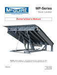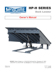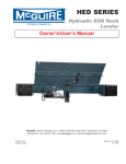
1
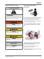
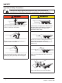
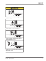
MA Series
Dock Leveler
Owner’s/User’s Manual
W.B.MCGUIRE • Division of Systems, Inc. • W194 N11481 McCormick Drive • Germantown, WI 53022
800.624.8473 • fax: 262.257.7399 • www.docksystemsinc.com • [email protected]
Printed in U.S.A.
Copyright © 2008
Manual No. 4111-0021
November 2009
Table of Contents
Page
Safety
Recognize Safety Information . . . . . . . . . . . . . . . . . . . . . . . . . . . . . . . 1
General Operational Safety Precautions . . . . . . . . . . . . . . . . . . . . . . 1
Operational Safety Precautions . . . . . . . . . . . . . . . . . . . . . . . . . . . . . 2
Maintenance Safety Precautions . . . . . . . . . . . . . . . . . . . . . . . . . . . . 4
Safety Decals . . . . . . . . . . . . . . . . . . . . . . . . . . . . . . . . . . . . . . . . . . . . 5
Introduction
General Information . . . . . . . . . . . . . . . . . . . . . . . . . . . . . . . . . . . . . . . 6
Dock Leveler Stock Specifications . . . . . . . . . . . . . . . . . . . . . . . . . . . 6
Component Identification . . . . . . . . . . . . . . . . . . . . . . . . . . . . . . . . . . 7
Theory . . . . . . . . . . . . . . . . . . . . . . . . . . . . . . . . . . . . . . . . . . . . . . . . . 7
Installation
Prepare Pit . . . . . . . . . . . . . . . . . . . . . . . . . . . . . . . . . . . . . . . . . . . . . . . 8
Prepare Dock Leveler . . . . . . . . . . . . . . . . . . . . . . . . . . . . . . . . . . . . . 9
Install Dock Leveler . . . . . . . . . . . . . . . . . . . . . . . . . . . . . . . . . . . . . . 10
Install Control Panel and Wiring . . . . . . . . . . . . . . . . . . . . . . . . . . . . 16
Put New Leveler Into Service . . . . . . . . . . . . . . . . . . . . . . . . . . . . . . 17
Operation
Operating Instructions . . . . . . . . . . . . . . . . . . . . . . . . . . . . . . . . . . . . 18
Ramp Loading/Unloading Instructions . . . . . . . . . . . . . . . . . . . . 19
End Loading/Unloading Instructions . . . . . . . . . . . . . . . . . . . . . 20
Maintenance
Service Dock Leveler Safely . . . . . . . . . . . . . . . . . . . . . . . . . . . . . . . 21
Periodic Maintenance . . . . . . . . . . . . . . . . . . . . . . . . . . . . . . . . . . . . . 22
Adjustments
Adjust Lip Latch and Lip Actuator Springs . . . . . . . . . . . . . . . . . . . 24
Adjust Lip Stop . . . . . . . . . . . . . . . . . . . . . . . . . . . . . . . . . . . . . . . . . . 27
Troubleshooting
Troubleshooting . . . . . . . . . . . . . . . . . . . . . . . . . . . . . . . . . . . . . . . . . 28
Electrical
Electrical 115/1 phase . . . . . . . . . . . . . . . . . . . . . . . . . . . . . . . . . . . . . 30
Parts
Controls . . . . . . . . . . . . . . . . . . . . . . . . . . . . . . . . . . . . . . . . . . . . . . . . 31
Pit Extension Kit . . . . . . . . . . . . . . . . . . . . . . . . . . . . . . . . . . . . . . . . . 32
Air Bladder and Support . . . . . . . . . . . . . . . . . . . . . . . . . . . . . . . . . . 33
Frane and Platform . . . . . . . . . . . . . . . . . . . . . . . . . . . . . . . . . . . . . . . 34
Weather Seal, Rubber Style . . . . . . . . . . . . . . . . . . . . . . . . . . . . . . . . 36
Weather Seal, Brush Style . . . . . . . . . . . . . . . . . . . . . . . . . . . . . . . . . 37
Motor and Blower Assembly . . . . . . . . . . . . . . . . . . . . . . . . . . . . . . 38
Miscellaneous
Customer Information . . . . . . . . . . . . . . . . . . . . . . . . . . . . . . . . . . . . 39
Warranty . . . . . . . . . . . . . . . . . . . . . . . . . . . . . . . . . . . . . . . . Back Cover
4111-0021 — November 2009
SAFETY
Recognize Safety Information
General Operational Safety
Precautions
Safety-Alert Symbol
The Safety-Alert Symbol identifies important safety
messages on equipment, safety signs, in manuals,
or elsewhere. When you see this symbol, be alert
to the possibility of personal injury or death. Follow
the instructions in the safety message.
Read and understand the operating instructions and
become thoroughly familiar with the equipment and
its controls before operating the dock leveler.
Never operate a dock leveler while a safety device or
guard is removed or disconnected.
The use of the word DANGER signifies the
presence of an extreme hazard or unsafe practice
which will most likely result in severe injury or
death.
The use of the word WARNING signifies the
presence of a serious hazard or unsafe practice
which may result in serious injury or death.
The use of the word CAUTION signifies possible
hazard or unsafe practice which could result in
personal injury.
IMPORTANT
The use of the word IMPORTANT is to draw
attention to a procedure that needs to be followed
to prevent machine damage.
Never remove DANGER, WARNING, or CAUTION
signs or decals on the equipment unless replacing
them.
e
Op
in g
rat
ne
Zo
g
tin
era
p
O
ne
Zo
Do not start the equipment until all unauthorized
personnel in the area have been warned and have
moved outside the operating zone.
Remove any tools or foreign objects from the
operating zone before starting.
Keep the operating zone free of obstacles that could
cause a person to trip or fall.
4111-0021 — November. 2009
1
SAFETY
Operational Safety Precautions
Learn the safe way to operate this equipment. Read and understand the
manufacturer's instructions. If you have any questions, ask your supervisor.
Stay clear of dock leveling device when freight
carrier is entering or leaving area.
Chock/restrain all freight carriers. Never remove
the wheel chocks until loading or unloading is
finished and truck driver has been given
permission to drive away.
Do not move or use the dock leveling device if
anyone is under or in front of it.
Do not use a broken or damage dock leveling
device. Make sure proper service and
maintenance procedures have been performed
before using.
Keep hands and feet clear of pinch points. Avoid
putting any part of your body near moving parts.
Make sure lip overlaps onto trailer at least 4 in.
(102 mm).
Keep a safe distance from both side edges.
2
4111-0021 — November 2009
SAFETY
Do not use dock leveling device if freight carrier is
too high or too low.
Do not overload the dock leveling device.
Do not operate any equipment while under the
influence of alcohol or drugs.
Do not leave equipment or material unattended on
dock leveling device.
4111-0021 — November. 2009
3
SAFETY
Maintenance Safety Precautions
ALWAYS disconnect electrical power source and
ground wire before welding on dock leveler.
DO NOT ground welding equipment to any
hydraulic or electrical components of the dock
leveler. Always ground to the dock leveler frame.
Failure to follow these instructions may result in
damage to dock leveler and/or serious personal
injury or death.
Hydraulic and electrical power must be OFF when
servicing the equipment. For maximum protection,
use an OSHA approved locking device to lock out
all power sources. Only the person servicing the
equipment should have the key to unlock the
device.
DO NOT grind or weld if hydraulic fluid or other
flammable liquid is present on the surface to be
ground or welded
DO NOT grind or weld if uncontained hydraulic
fluid or other flammable liquid is present. Stray
sparks can ignite spills or leaks near the work area.
Always clean up the oil leaks and spills before
proceeding with grinding or welding.
Always keep a fire extinguisher of the proper type
nearby when grinding or welding.
Always post safety warnings and barricade the
work area at dock level and ground level to
prevent unauthorized use of the unit before
maintenance is complete.
Failure to follow these instructions may result in
serious personal injury or death.
ALWAYS stand clear of dock leveler lip when
working in front of the dock leveler. Failure to do
this may result in serious personal injury or death.
The maintenance prop must be in the upright
"service" position when working under the dock
leveler. For maximum protection, use an OSHA
approved locking device to lock the maintenance
prop in the service position. Only the person
servicing the equipment should have the key to
unlock the device.
4
4111-0021 — November 2009
SAFETY
Safety Decals
Every 90 days (quarterly) inspect all safety labels and tags
to ensure they are on the dock leveler and are easily legible. If any are missing or require replacement, please call
1-800-643-5424 for replacements.
DANGER
CRUSH HAZARD
Maintenance prop must
support leveler behind bar.
Do not force maintenance
prop forward of bar to
support lip. Refer to
owner’s/user’s manual for
proper use. Failure to
comply will result in
death or serious injury.
1751-0727
1751-0727
1751-0730 (x2)
DANGER
SAFETY INFORMATION
Unsupported dock leveler
ramps can lower unexpectedly.
Before allowing vehicle to leave
the dock always:
!
Ensure that no equipment,
material or people are on the
dock leveler.
!
Return the dock leveler to its
stored position at dock level.
Failure to follow posted instructions will result in death or serious injury.
Operation
1. Read and follow all instructions and
warnings in the owner’s/user’s
manual.
2. Use of dock leveler restricted to
trained operators
3. Always chock trailer wheels or
engage truck restraint before
operating dock leveler or beginning to
load or unload.
4. Never use hands or equipment to
move the ramp or lip
5. Before activating dock leveler:
¥ Ensure trailer is backed in against
bumpers.
¥ Remove any end loads if required.
¥ Check trailer alignment to avoid lip
interference. If lip does not lower to
trailer bed, reposition vehicle.
6. Ensure that truck bed supports
extended lip or the leveler frame
supports the ramp before driving on
ramp.
7. Stay clear of hinges and front and
sides of moving dock leveler.
8. Never use damaged or
malfunctioning dock leveler. Report
problems immediately to supervisor.
Maintenance/Service
1. Read and follow all instructions,
warnings and maintenance schedules
in the owner’s/user’s manual.
2. Maintenance/Service of dock leveler
restricted to trained personnel.
3. Place barriers on the driveway and on
dock floor to indicate service work is
being performed.
4. DO NOT ENTER PIT unless dock
leveler is securely supported by
maintenance prop.
5. If electrically powered turn off and use
OSHA lockout/tagout procedures.
Call 262.255.1510 for replacement placards, warning labels, or owner’s/user’s manuals.
(decal placed in same position on both sides)
1751-0329 (x2)
DO NOT
FORK THIS SIDE
(decal placed in same position on both sides)
FORK
HERE
1751-0330 (x2)
(decal placed in same position on both sides)
1751-0729
DANGER
CRUSH HAZARD
Do not work under dock leveler unless this maintenance prop has been secured in the
upright position. See owner’s/user’s manual for proper procedures. Failure to comply
1751-0729
will result in death or serious injury.
DANGER
1751-0731
CRUSH HAZARD
Open the pin latch and insert
through the maintenance
prop housing and prop
completely. Close the pin latch
to secure prop. Use every
time dock leveler is serviced.
Failure to comply will result
in death or serious injury.
1751-0731
DANGER
1751-0726
CRUSH HAZARD
DO NOT ENTER PIT unless dock leveler is
safely supported by maintenance prop. Place
barriers on driveway and dock floor to indicate
service work being performed. Refer to
owner’s/user’s manual for proper maintenance
procedures. Failure to comply will result in death
or serious injury.
1751-0726
4111-0021 — November. 2009
5
INTRODUCTION
General Information
Dock Leveler Stock Specifications
MA-Series dock levelers are available in the following
sizes, weight capacities, and options:
Width: MA
6 ft (1828.8 mm)
6-1/2 ft (1981.2 mm)
7 ft (2133.6 mm)
Length
6 ft (1828.8 mm)
8 ft (2438 mm)
10 ft (3048 mm)
Congratulations on your choice of a McGUIRE dock
leveler. This manual covers the Air Bag, MA model
air powered dock leveler.
Designed by McGUIRE to be a marvel of simplicity
and efficiency, your dock leveler, when properly
installed, will provide many years of trouble-free
performance with an absolute minimum of
maintenance. Its revolutionary air bag system
efficiently controls and operates every function. To
obtain maximum performance and longest possible
use, a simple program of preventive maintenance is
recommended.
Capacity (CIR*)
25,000 lb (11,340 kg)
30,000 lb (13,608 kg)
35,000 lb (15,876 kg)
40,000 lb (18,144 kg)
45,000 lb (20,412 kg)
55,000 lb (22,680 kg)
* CIR (Comparative Industry Rating)
All docks are available in 115V motors only.
The MA dock leveler comes equipped with an
electrical control panel, which allows push button
operation of the dock leveler functions. Each MA
dock leveler unit and control panel has been factory
prewired and tested to ensure satisfactory operation.
To illustrate which connections are to be made in the
field at installation, electrical drawings are included
with each order or by contacting Poweramp Technical
Services.
Once again, thank you and congratulations on your
purchase of a McGUIRE MA dock leveler.
6
4111-0021 — November 2009
INTRODUCTION
O
Component Identification
A
C
P
N
D
B
J
H
G
K
F
I
A — Lip
E — Lip Maintenance Prop Pivot)
B — Lip Assist Rod
F — Lip Actuator Snubber Spring
C —Lip Linkage Assembly G — Lip Actuator Chain
D — Lip Latch Assembly
E
H — Air bag support pallet
I — Lip Keepers (2 used)
J — Air bag
K — Main Frame
L
M
L — Maintenance Prop
M —Blower Motor
N —Toe Guard (2 used)
O —Raise Button
P —Safety Legs
THEORY
The MA dock leveler uses a blower motor and
one-button operation for ease of use.
The dock leveler can be operated remotely using the
RAISE button (O) on the control panel . This
activates an electric blower motor (M). The blower
forces air into the air bag (J), causing the platform to
rise. Releasing the RAISE button allows the platform
to lower.
When the platform rises to the point where there is
2 — 3 in. (51 — 76. mm) from its full raised height, the
lip spring (F) and lip actuator chain (G), causes the
lip linkage assembly to push the lip out and up. The
lip assist spring (not shown) also helps keep the lip
extended. When the lip is fully extended, the lip latch
cable engages the lip latch assembly, locking the lip
in the extended position. The dock leveler has
reached its full height when the lip is fully extended.
4111-0021 — November. 2009
To lower the platform, release the Raise button (O).
The platform will lower until the extended lip rests on
the truck bed. If the lip did not fully extend or there is
no truck at the dock the platform will lower until one
of the following conditions occur:
-- Lip is resting on lip keepers (cross-traffic position).
-- Leveler went to the below-dock position, lip folds
automatically, leveler rests on the safety legs
(below dock position).
-- Leveler went to the below dock position with
operator holding the safety leg retract cable
(not shown), safety legs are retracted, lip folds
automatically causing dock to rest in the full below
dock position.
7
INSTALLATION
Prepare Pit
14”
A
C
B
10”
D
A—Distance (Pit Width)
(Front and Rear)
B— Distance (Dock Floor-to-Pit
Floor) (All Four Corners)
C— Distance (Pit Length)
(Both Sides of Pit)
D— Distance (Pit Corner-to-Corner)
(Top, Bottom, and Both Sides)
Before lowering the dock leveler into the pit, the
following must be performed:
Post safety warnings and barricade the work area
at dock level and ground level to prevent
unauthorized use of the dock leveler before
installation has been completed.
Failure to follow the installation instructions can
result in damage to dock leveler, the facilities,
and/or serious personal injury or death.
Only trained installation professionals with the
proper equipment should install this product.
IMPORTANT
DO NOT remove the shipping bands around the
dock leveler lip until instructed to do so.
1. Remove all debris from the pit and sweep the pit
clean.
2. Check the entire dock leveler pit for proper
construction according to approved/certified pit
drawings. Make sure pit is square by making the
following measurements:
• Measure pit width distance (A) at both front
and rear of pit.
• Measure dock floor-to-pit floor distance (B) at
all four corners.
• Measure pit length distance (C) at both sides.
• Measure corner-to-corner (criss-cross) distance
(D) at both sides. Take measurements at dock
floor level and at pit floor level.
If any measurement is off by more than 1/8 in.
(3.18 mm), contact Poweramp Technical Services
before proceeding.
3. Make sure the field junction box for the dock
leveler (E) is at the correct location per pit
diagrams.
8
4111-0021 — November 2009
INSTALLATION
Prepare Dock Leveler
IMPORTANT
DO NOT remove the shipping bands (B) around
the platform lip and leveler frame at this time. The
shipping bands are needed to hold the leveler
together during the installation process.
A
1. Remove any control panel and bumpers that may
be banded to the frame of the dock leveler.
DO NOT remove the shipping bands (B) around
the platform lip and leveler frame at this time.
IMPORTANT
B
A— Lifting Bracket (2 used)
DO NOT over tighten the lifting bracket hardware.
Over tightening can damage the weather seal, if
equipped.
B — Shipping Bands
McGUIRE dock levelers are designed with installation
in mind. Each unit is shipped with lifting brackets (A)
fastened to the platform side joists.
NOTE: Overall width of platform and lifting brackets
(A) must be kept to a minimum to prevent
interference between the lifting brackets and
the pit walls as the dock leveler is lowered
into the pit.
The dock leveler is heavy. Use a lifting device and
chains with the appropriate lifting capacity and
reach.
2. Make sure the mounting hardware of lifting
brackets (A) is snug. The brackets should pivot
relatively freely on the mounting cap screw. DO
NOT over tighten.
Always use the lifting brackets provided with the
unit whenever lowering or lifting a dock leveler into
or out of a pit.
3. Attach lifting chains to lifting brackets (A) and to a
lifting device (i.e., hoist or fork truck) having the
appropriate lifting capacity and reach.
Failure to follow these instructions may result in
damage to dock leveler and/or serious personal
injury or death.
4. Remove wood blocks that are attached to the
leveler frame before putting the dock leveler into
the pit.
5. Attach a temporary, switched, power supply to the
blower before lowing leveler into pit. Keep power
cables clear of frame members, shim locations
and pinch points. DO NOT CONNECT POWER
AT THIS TIME.
4111-0021 — November. 2009
9
INSTALLATION
Install Dock Leveler
Shim
Stacking Methods
N
P
Q
R
A— Distance (Leveler Frame
Height)
B— Shim Locations (Under
Rear Vertical Supports,
4-5 Places TYP)
C— Shim Locations (Under
Lip Keepers,
C —Shim Under Snubber
Spring Mount
D— Dock Floor
E— Rear Pit Curb Angle
10
F— String
G— Rear Hinge Frame Angle
H— Distance (Dock Floor-toPit Floor)
J— Distance (Top of Shim
Stack-to-Dock Floor)
K— Shim Stack
L— Dock Leveler Frame
M — Pyramid (Preferred)
N— Stepped (Acceptable)
P— Offset (Not Acceptable)
Q — Straight (Not Acceptable)
4111-0021 — November 2009
INSTALLATION
NOTE: McGUIRE dock levelers are designed with a
nominal 1/2 in. (12.7 mm) shimming distance
to allow for pit inconsistencies.
4. For all MA models, put a 1/4 in. (6.6 mm) thick
shim at locations (B and C) .
1. Determine height of shim stack (L) for each shim
location (B) by performing the following:
NOTE: A 1/4 in. (6.6 mm) thick shim at locations (B
and C) is used only as a starting point. The
final shim stack height will be determined
after dock leveler is lowered into the pit.
a. Measure leveler frame height distance (A).
b. Measure dock floor-to-pit floor distance (J) at
each shim location (B). Write down the
dimensions obtained at each location.
c. Subtract distance (A) from distance (J) to obtain
the shim height. Repeat for each shim location.
IMPORTANT
The minimum size of the shim that contacts the
leveler frame (i.e., the top shim of each shim stack)
must be at least 4-1/2 x 4-1/2 in. (114.3 x 114.3
mm) to support the full width of the frame rail and
to provide a shelf for a fillet weld.
Use the thickest shim stock possible for stability
and weld penetration purposes. DO NOT use
multiple layers of 1/8 in. (3.18 mm) or thinner shim
stock.
2. Using the results obtained in step 1, create the
individual shim stacks on the pit floor at locations
(B). Build each shim stack (L) using the pyramid
method (N) (preferred) or stepped method (P) with
the top shim having a minimum size of 4-1/2 x
4-1/2 in. (114.3 x 114.3 mm) and each successive
lower shim being larger so the shims can be
welded together using a fillet weld. DO NOT use
offset method (Q) or straight method (R).
The dock leveler is heavy. Use chains and a lifting
device with the appropriate lifting capacity and
reach. Failure to do so may result in damage to
dock leveler and/or serious personal injury or
death.
5. Using an appropriate lifting device connected to
the lifting brackets, lower dock leveler into the pit
so rear hinge frame angle (G) is tight against rear
pit curb angle (E) across full width of the leveler
frame.
6. Allow rear of dock leveler to rest on the rear
shims while keeping the front of the dock leveler
level with the dock floor.
7. For all MA models, add shims at front shim
locations (C) so front of dock leveler will stay level
with dock floor when leveler is resting fully on
shims.
NOTE: To assist in obtaining an accurate
measurement of distance (K), use a string
(G) pulled tight across the pit opening,
directly over the shim locations.
3. Verify that each shim stack is at the correct height
by measuring distance (K) [top of shim stack (L) to
dock floor]. Distance (K) must equal the dock
leveler height (A).
4111-0021 — November. 2009
11
INSTALLATION
B
A
C
C
D
D
E
F
G
A— Front of Dock Pit
B— Dock Leveler Frame
3/8 in.
(9.5 mm)
6 in.
(152 mm)
C— Side Pit Curb Angle
D— Gap [3/4 in. (19 mm)
Minimum]
8. With rear hinge frame angle (F) tight against rear
pit curb angle (G), perform/check the following:
• Pry between the platform and rear hinge frame
angle at locations (E) to make sure rear edge
of platform is parallel to the rear hinge frame
angle (F).
• Gap (D) must exist equally along both sides of
leveler so weather seal (if equipped) will not
bind during dock leveler operation.
12
H
E— Pry Locations
G— Rear Pit Curb Angle
F— Rear Hinge Frame Angle H— Flare Bevel Weld, Typical
(To Fit Spacing)
9. If gap (D) cannot be obtained equally at both
sides of leveler, grind or add material at the rear
edge of rear hinge frame angle (F) as needed.
10. Allow the dock leveler to rest fully on the shim
stacks. Check that a smooth and level transition
exists between the dock floor and the dock
leveler platform. Add or remove shims as
necessary until a smooth transition is obtained.
11. If leveler cannot be squared and/or made level
as instructed in steps 8 — 10, contact McGUIRE
Technical Services.
4111-0021 — November 2009
INSTALLATION
12.With the leveler square in the pit and flush with
the surrounding dock, remove the
banding on the lip of the leveler.
13. Connect the blower motor to the temporary
power supply.
Two people are required to engage the
maintenance prop: one person to operate the lifting
device, the other person to engage the
maintenance prop.
14. Slowly raise the platform. Check for binding as
platform is being raised.
15. If binding occurs, lower the platform. Reposition
leveler and/or add or remove shims as
necessary. Slowly raise platform again. If platform
still binds, contact Poweramp Technical Services
for further instructions.
16. All MA models - Once leveler is flush, square and
does not bind:
a. Install shims under maintenance prop (C)
page 10, where prop attaches to leveler
frame. Make sure prop is solidly shimmed.
DO NOT use the maintenance prop to support the
raised platform until the maintenance prop has
been properly shimmed and welded. The shims
must be welded to each other, the leveler frame,
and to the front pit curb steel. Failure to do this
may result in serious personal injury or death.
c.Raise maintenance prop to the service
(upright) position and lock prop in this
position using an OSHA approved locking
device.
17. Disconnect power supply from motor.
b. Using the leveler’s blower motor, raise the
dock to the fully open position.
IMPORTANT
DO NOT weld before disconnecting all electrical
components.
DO NOT weld before removing air bag, air bag
support pallet and hoses from leveler.
Protect or remove the blower motor before welding.
figure 1
Failure to follow these instructions may result
damage to these components from stray sparks
and weld splatter that will void your warranty.
18. Remove air bag and pallet support from the
leveler by disconnecting air bag positioning rods
from hooks on the underside of platform.(figure
1) and removing the band clamp from the motor
coupler. (figure 2)
19. Remove or protect the blower motor from weld
sparks and splatter.
Proceed to step 17.
figure 2
4111-0021 — November. 2009
13
INSTALLATION
IMPORTANT
DO NOT grind or weld if hydraulic fluid or other
flammable liquid is present on the surface to be
ground or welded.
DO NOT grind or weld if uncontained hydraulic
fluid or other flammable liquid is present. Stray
sparks can ignite spills or leaks near the work area.
Always clean up the oil leaks and spills before
proceeding with grinding or welding.
Always keep a fire extinguisher of the proper type
nearby when grinding or welding.
Failure to follow these instructions may result in
serious personal injury or death.
IMPORTANT
DO NOT connect the dock leveler electrical wiring
and ground connections until all welding has been
completed.
DO NOT weld continuously along the full length of
the rear hinge frame angle. This can put
unnecessary stress on the leveler components,
causing the leveler to malfunction and shorten the
life span of the affected components.
NOTE: The illustration on page 12 shows a typical
weld pattern. The weld pattern will vary
slightly depending on size of dock leveler.
20. With the rear hinge frame angle (F) tight against
the rear pit curb angle and flush with the curb
angle (G), weld the rear hinge frame angle (F) to
the rear pit curb angle (G) using a 3/8 in. (9.5
mm) flare bevel skip weld
— each weld being 6 in. (152 mm) long.
Start at each end with a 6 in. (152 mm) long
weld. Space all the other welds out evenly
leaving approximately 6 in. (152 mm) space
between each weld.
DO NOT ground welding equipment to any
hydraulic or electrical components of the dock
leveler. Always ground welding equipment to the
dock leveler frame, NEVER to the platform.
Failure to follow these instructions may damage the
motor, wiring, and/or control panel.
14
4111-0021 — November 2009
INSTALLATION
Make sure the platform is properly supported in the
raised position before entering the pit to finish weld
the shims. Failure to do this may result in serious
personal injury or death.
21. All model levelers: Install shims at locations (B,
p.10) using the pyramid or stepped shimming
method. Make sure the platform is level from
side-to-side as well as from front-to-back and
flush with dock floor.
22. Weld front of dock leveler frame (C) to shims
located under the keepers, then weld the shims
to the front pit curb steel.
23. Finish weld all shims using a fillet weld.
• Weld all shims within each shim stack to each
other, then weld the shim stack to the leveler
frame.
• Weld the front leveler frame shim stacks to the
front pit curb steel.
24. When all welding has been completed, paint all
the welds and shims.
Shim
Stacking Methods
N
P
Q
R
* For left/right orientation of dock leveler, see inside back cover of
this manual.
4111-0021 — November. 2009
15
INSTALLATION
Install Control Panel and Wiring
A
The electrical power must be OFF prior to electrical
installation. For maximum protection, use an OSHA
approved locking device to lock out all power
sources. Only the person installing the equipment
should have the key to unlock the power source.
Failure to follow these instructions may result in
serious personal injury or death.
B
C
DO NOT make any final electrical connections until
all welding has been completed. Failure to do this
may result in serious personal injury or death.
All electrical work — including the installation of the
disconnect panel, control panel, and final
connections to the pit junction box — must be
performed by a certified electrician and conform to
all local and applicable national codes.
A— Disconnect Panel (provided by others)
B— Control Panel
C— Distance, 48 in. (14 630 mm)
1. Mount the push button control panel (B) so bottom
of control panel-to-dock floor distance (C) is 48 in.
(1219.2 mm).
2. Install electrical disconnect panel (A) if not already
installed.
3. Install and connect the control wiring.
4. Re-install the air bag, air bag support pallet and
blower motor.
5. Connect the dock leveler power cable to the outlet
in the pit junction box. Refer to the electrical
drawings supplied with the dock leveler.
6. After all electrical connections in the pit have been
made, raise the leveler, disengage the
maintenance prop and allow the platform to lower.
16
4111-0021 — November 2009
INSTALLATION
Put New Dock Leveler Into Service
1. Disconnect the external lifting device and chains
from the lifting brackets.
2. Check that the leveler is flush with the dock floor
and that the platform lip contacts both lip keepers
evenly.
If an excessive transition exists between the dock
floor and leveler and/or lip does not contact both
lip keepers evenly, contact Poweramp Technical
Services for further instructions.
7. When the platform lowers to the full below-dock
position, the lip will fold. Push and hold the
RAISE button until the platform rises just enough
to clear the lip keepers, then release the RAISE
button to allow the platform to lower to the
cross-traffic (stored) position (lip engages lip
keepers).
8. Perform steps 5 – 7 at least four times make sure
the leveler functions properly and there is no
binding.
3. Install the dock bumpers as required.
4. Turn the main electrical power ON.
Always stand clear of platform lip when working in
front of the dock leveler. Serious personal injury or
death may result.
5. Raise the leveler platform fully by pushing and
holding the RAISE button .
NOTE: The platform of a properly operating dock
leveler will automatically stop rising when it
reaches approximately 2 – 3 inches from its
full raised height, at which point, the lip
extends. When the lip is fully extended, it has
reached the full raised position. (If the lip
does not extend or extend fully, see Platform
Rises to Full Height, But Lip Does Not Fully
Extend in the Troubleshooting section.)
6. Release the RAISE button to lower the platform.
As long as there is no truck present at the dock,
the platform will lower to the full below-dock
position as the lip folds.
NOTE: If a truck is present, the platform will lower
until the lip rests on the truck/trailer bed. (See
Operating Instructions in Operation section.)
4111-0021 — November. 2009
Unless the dock leveler is equipped with a tethered
remote, two people are required to engage the
maintenance prop: one person to operate the unit,
the other person to engage the maintenance prop.
9. Raise the platform fully. Hold the platform at this
position using the RAISE button and
move the maintenance prop to the
service (upright) position. Release the RAISE
button to allow the platform to lower until it is
resting on the maintenance prop.
10. With the maintenance prop supporting the
platform, remove the lifting brackets
11. If equipped with vertical weather seals, position
the seals so that the seals are directly under and
aligned with the overhead door.
12. Support the toe guards, remove the bolt used in
shipping and carefully release the toe guards.
13. Push and hold the RAISE button until the
maintenance prop drops to its stored position.
Release the RAISE button and allow the platform
to lower fully. Check operation of toe-guards.
14. When the platform lowers to the full below-dock
position, the lip will fold. Push and hold the
RAISE button until the platform rises just enough
to clear the lip keepers, then release the RAISE
button to allow the platform to lower to the
cross-traffic (stored) position (lip engages lip
keepers).
17
OPERATION
Operating Instructions
Stay clear of dock leveler when freight carrier is
entering or leaving dock area.
12 in. (305 mm)
DO NOT move or use the dock leveler if anyone is
under or in front of leveler.
12 in. (305 mm)
Keep hands and feet clear of pinch points. Avoid
putting any part of your body near moving parts.
Failure to follow these instructions may result in
severe personal injury or death.
Only trained personnel should operate the dock
leveler.
The MA pneumatic dock leveler is designed to
compensate for a maximum ± 12 in.* (305 mm) of
height difference between the loading dock and the
truck bed. DO NOT use the dock leveler if the
truck/trailer bed is more than 12 in. (305 mm)
higher or lower than the dock floor.
*service height may vary with design specifications
DO NOT overload the dock leveler.
DO NOT use a broken or damaged dock leveler.
Make sure proper service and maintenance
procedures have been performed on leveler before
using.
Truck/trailer wheels must be chocked unless the
truck restraint is used. Never remove the wheel
chocks until loading/unloading is finished and truck
driver has been given permission to leave.
Make sure platform lip rests on the truck/trailer bed
with at least 4 in. (102 mm) of overlap.
Maintain a safe distance from side edges of leveler
during the loading/unloading process.
Failure to follow these instructions may result in
serious personal injury or death.
18
DO NOT operate any equipment while under the
influence of alcohol or drugs.
DO NOT leave equipment or material unattended
on the dock leveler.
Failure to follow these instructions may result in
personal injury and/or damage to equipment.
The dock leveler operating instructions are
divided into the two methods of loading and
unloading:
• For ramp loading and unloading, see Ramp
Loading/Unloading Instructions on page 19.
• For end loading and unloading, see End
Loading/Unloading Instructions on page 20.
4111-0021 — November 2009
OPERATION
Operating Instructions—Continued
Below Dock Loading/Unloading Instructions
Ramp Loading/Unloading Instructions
NOTE: If end unloading is required, see End
Loading/Unloading Instructions on page 20.
NOTE: If end unloading is required, see End
Loading/Unloading Instructions on page 20.
7. Check to make sure truck/trailer is positioned
squarely against dock bumpers.
For ramp loading or unloading, the MA dock
leveler can be operated by using the RAISE
button on the control panel.
8. Instruct driver to remain at the dock until the
loading or unloading process has been
completed.
1. Check to make sure truck/trailer is positioned
squarely against dock bumpers.
9. Chock the truck/trailer wheels or use truck
restraint if present.
2. Instruct driver to remain at the dock until the
loading or unloading process has been completed.
10. Raise the platform by pushing the raise button (A)
to fully raise the leveler and extend the lip.
3. Chock the truck/trailer wheels or use the truck
restraint if available.
11. Walk out on the leveler, Pull and Hold the release
ring (see picture below) until the platform lowers
onto the trailer. Make sure there is a minimum of
4” of lip overlapping the trailer.
A
A-RAISE Button
4. Extend the platform lip onto truck/trailer as follows:
a. Raise the platform by pushing and holding
RAISE button .
Loading/Unloading Completed - Reset Leveler
b. Hold the RAISE button until the lip is fully
extended, then release the RAISE button. The
platform will lower until the lip is resting on the
truck/trailer bed.
c. Make sure that the lip is fully extended and
supported on the truck/trailer along the entire
width of the platform with at least 4 in. (102 mm)
of lip contacting the truck bed.
A
A—RAISE Button
12. When loading or unloading is finished, raise the
platform by pushing and holding RAISE button
(A) .
13. Hold the RAISE button until the lip folds enough
to clear the truck/trailer bed, then release the
RAISE button. The lip will fold and the platform
will return to the cross-traffic position.
5. Proceed with loading or unloading the truck/trailer.
6. If below dock loading is necessary, see steps
7-11. If not, proceed to step 12.
14. Remove chocks from truck/trailer wheels or
release the truck restraint if used.
15. Indicate to driver that truck may leave the dock.
4111-0021 — November. 2009
19
OPERATION
Operating Instructions—Continued
End Loading/Unloading Instructions
NOTE: If ramp loading is required, see Ramp
Loading/Unloading Instructions on page 19.
End loading or unloading can be done with
the dock at the cross-traffic position or
below-dock position, depending on the height
of the truck/trailer bed.
1. Check to make sure truck/trailer is positioned
squarely against dock bumpers.
2. Instruct driver to remain at the dock until the
loading or unloading process has been completed.
3. Chock the truck/trailer wheels or use the truck
restraint if available.
6. Push the Raise button to the platform high
enough to clear the lip keepers, but not high
enough to extend the lip.
7. Walk out on the leveler, pull and hold the safety
leg retract pull ring (B) (located in the recess at
the front of the platform). This will cause the lip to
extend away from the lip keepers and the cross
traffic safety legs to fold to allow the leveler to
lower to the below dock position.
8. When the platform lip clears the lip keepers,
continue to hold the pull chain as the leveler
lowers to the below-dock service position. The
platform will drift down to the full below-dock
position.
9. Proceed with loading or unloading.
End Loading/Unloading — Platform at Cross-Traffic Position.
4. If truck/trailer bed is at or above dock floor level,
leave leveler at the cross-traffic position and
proceed with loading or unloading.
NOTE: When end unloading is finished and access
to the rest of the truck/trailer is still required,
the platform lip will need to be extended. See
Ramp Loading/Unloading Instructions on
page 19 for further instructions.
10. When the loading or unloading is finished, return
the dock leveler platform to the cross-traffic
(stored) position.
End Loading/Unloading — Platform Too High
Use Below-Dock Position.
5. If truck/trailer bed is below the dock floor level,
perform steps 6 –12.
11. Push the Raise button (A) until the lip clears the
lip keepers. Release Raise button, leveler will
return to the stored or cross traffic position.
12. Remove chocks from truck/trailer wheels or
release the truck restraint if used.
13. Indicate to the driver that the truck may leave the
dock.
End Loading/Unloading — Platform at Below-Dock Position.
20
4111-0021 — November 2009
MAINTENANCE
Service Dock Leveler Safely
E
A— Maintenance Prop
B —Prop Pin and Clip C —Safety Leg Chain
When service under the dock leveler is required,
always lock all electrical disconnects in the OFF
position after raising the platform and engaging the
maintenance prop. Failure to do this may result in
serious personal injury or death.
Always stand clear of the dock leveler lip when
working in front of the dock leveler.
The maintenance prop MUST be in the service
position when working under the dock leveler. For
maximum protection, use an OSHA approved
locking device to lock the maintenance prop in the
service position. Only the person servicing the
equipment should have the key to unlock the
maintenance prop.
Unless the dock leveler is equipped with a tethered
remote, two people are required to engage the
maintenance prop: one person to operate the unit,
the other person to engage the maintenance prop.
Failure to follow these instructions may result in
serious personal injury or death.
4111-0021 — November. 2009
D —Lip Prop
E.— Lock Out Tag Out
Always post safety warnings and barricade the
work area at dock level and ground level to prevent
unauthorized use of the dock leveler before
maintenance is complete. Failure to do this may
result in serious personal injury or death.
Whenever performing maintenance under the dock
leveler platform, support the platform with the
maintenance prop (A). Position the maintenance prop
behind front header plate while staying clear of the
lip. The lip will fold down after the platform has rested
on the maintenance prop. The Lip Prop may be used
to keep the lip extended (D). Additional supports
should be used to prevent the lip from collapsing if
working under the leveler. Lock the maintenance
prop in the service (B) position using an OSHA
approved lockout/tagout device* (E).
Whenever servicing the dock leveler, lock the
electrical power disconnect in the OFF position. Use
only an OSHA approved lockout/tagout device* (E).
Only the person servicing the equipment should have
the capability to remove the lockout/tagout devices.
The Tag out devices* must inform that repairs are in
process and clearly state who is responsible for the
lockout condition. * Refer to OSHA regulation 1910.147.
21
MAINTENANCE
Periodic Maintenance
Always stand clear of the dock leveler lip when
working in front of the dock leveler.
The maintenance prop MUST be in the service
position when working under the dock leveler. For
maximum protection, use an OSHA approved
locking device to lock the maintenance prop in the
service position. Only the person servicing the
equipment should have the key to unlock the
maintenance prop.
Unless the dock leveler is equipped with a tethered
remote, two people are required to engage the
maintenance prop: one person to operate the unit,
the other person to engage the maintenance prop.
Failure to follow these instructions may result in
serious personal injury or death.
Before performing any maintenance under the
dock leveler, lock the electrical power source in
OFF position and lock the maintenance prop in the
service position using an approved locking device.
(See Service Dock Leveler Safely in this section.)
Under platform service
Failure to follow these instructions may result in
serious personal injury or death.
Air Filter, service under rear of platform
22
4111-0021 — November 2009
MAINTENANCE
Regular maintenance must be performed on a
weekly and quarterly schedule.
Weekly Maintenance
Quarterly Maintenance
• Operate the dock leveler through the complete
operating cycle to maintain lubrication.
• Perform Weekly Service Items
NOTE: To thoroughly inspect the platform hinge
area, put the platform in the full below-dock
position.
• Inspect the platform hinge and the lip hinge areas.
The hinge areas must be kept free of dirt and
debris. Build-up of foreign material in the hinge
areas will cause abnormal operation.
• Inspect the area under the platform, around and
under the air bag. Build-up of foreign material in
this area may damage air bag components,
causing abnormal operation.
• Lubricate the following areas with light weight
machine oil:
(A)— Lip hinge area unless equipped with
grease fittings (apply oil to the top of
the entire length of lip hinge when platform is
at the full below-dock position and lip is
folded)
(B)— Platform hinge area (apply oil to top of all
platform hinges when platform is at the full
below-dock position)
NOTE: Apply grease to lip hinge grease fittings if
equipped.
IMPORTANT
Failure to properly lubricate the dock leveler will
cause abnormal operation of the leveler.
• Lubricate the following areas with light-weight
machine oil:
(C)— Lip maintenance prop pivot
(D)— Lip link pivots
(E)— Safety leg linkage pivots
• Lubricate the following areas with white lithium
grease (if equipped with grease fittings):
(A)— Lip hinge area (inject grease into all the lip
hinge grease fittings)
(B)— Platform hinge area (inject grease into all the
platform hinge grease fittings)
(F)— Lip assist pin
4111-0021 — November. 2009
23
ADJUSTMENTS
Adjusting the Latch and Lip Actuator Spring Tension
When service under the dock leveler is required,
always lock all electrical disconnects in the OFF
position after raising the platform and engaging the
maintenance prop. Failure to do this may result in
serious personal injury or death.
Always post safety warnings and barricade the
work area at dock level and ground level to prevent
unauthorized use of the dock leveler before
maintenance is complete. Failure to do this may
result in serious personal injury or death.
A
Always stand clear of the dock leveler lip when
working in front of the dock leveler.
B
The maintenance prop and lip maintenance prop
MUST be in the service position when working
under the dock leveler. For maximum protection,
use an OSHA approved locking device to lock the
maintenance prop in the service position. Only the
person servicing the equipment should have the
key to unlock the maintenance prop.
Unless the dock leveler is equipped with a tethered
remote, two people are required to engage the
maintenance prop: one person to operate the unit,
the other person to engage the maintenance prop.
A— Lip Latch Spring
Adjustment
B— Lip Assist Spring
Adjustment
Failure to follow these instructions may result in
serious personal injury or death.
24
4111-0021 — November 2009
ADJUSTMENTS
Adjusting Lip Latch Spring Tension
Adjusting Lip Assist Spring Tension
This adjustment is set at the factory and should not
require additional adjustment.
This adjustment is set at the factory and should not
require additional adjustment.
Unlike mechanical levelers, the lip will not
immediately begin to fold as the platform returns to
the stored position.
Unlike mechanical levelers, the lip will not
immediately begin to fold as the platform returns to
the stored position.
After the platform is fully raised, and the lip extends,
the lip latch is designed to hold the lip in the
extended position until the platform drifts down to the
below dock position.
The MA leveler lip remains extended as the platform
drifts down to the below dock position. The lip will
automatically fold when the platform when the dock is
resting on the safety legs in the below dock position.
If the lip does not remain extended as the platform
lowers, additional spring tension may be required.
If the lip does not fully extend additional spring
tension may be needed.
NOTE: Use half-turn increments when adjusting lip
assist spring. Check lip operation after each
adjustment. Repeat until proper operation is
obtained.
NOTE: Use two-turn increments when adjusting lip
assist spring. Check lip operation after each
adjustment. Repeat until proper operation is
obtained.
Adjust spring tension as follows:
Adjust spring tension as follows:
a. Loosen jam nut (A).
a. Loosen jam nut (A).
b. To increase spring tension, turn nut (B) counter
clockwise.
b. To increase spring tension, turn nut (B)
clockwise.
c. To decrease spring tension, turn nut (B)
clockwise.
c. To decrease spring tension, turn nut (B)
counterclockwise.
d. Tighten jam nut.
d. Tighten jam nut.
Recheck operation of platform and lip. Readjust lip
latch spring tension and lip assist spring tension until
proper operation is obtained.
4111-0021 — November. 2009
Recheck operation of platform and lip. Readjust lift
spring tension and lip assist spring tension until
proper operation is obtained.
25
This page intentionally left blank.
26
4111-0021 — November 2009
ADJUSTMENTS
Adjust Lip Stop Bolt
Always post safety warnings and barricade the
work area at dock level and ground level to prevent
unauthorized use of the dock leveler before
maintenance is complete. Failure to do this may
result in serious personal injury or death.
A
B
Always stand clear of the dock leveler lip when
working in front of the dock leveler. Failure to do
this may result in serious personal injury or death.
C
E
The platform maintenance prop MUST be in the
service position when working under the dock
leveler. For maximum protection, use an OSHA
approved locking device to lock the maintenance
prop in the service position. Only the person
servicing the equipment should have the key to
unlock the maintenance prop.
Failure to follow these instructions may result in
serious personal injury or death.
D
A— Platform Frame
B— Jam Nut
C— Stop Bolt
D — Lip Keeper
E — Lip
Check that lip (E) is fully resting on the lip keepers
(D) and at the lowest part of the keeper cradle. If lip
is not resting properly in keepers, perform the
following adjustment.
4. Tighten jam nut.(B)
1. Fully raise platform. Engage lip and maintenance
prop.
6. Allow platform to lower to cross-traffic (stored)
position.
2. Loosen jam nut (B).
7. Check lip position in both keepers. Repeat
procedure if necessary.
5. Fully raise platform and disengage lip and
maintenace prop.
3. Adjust stop bolt (C) as necessary.
• Turn stop bolt “in” (clockwise) to allow lip to fold
closer to platform frame (A).
• Turn stop bolt “out” (counterclockwise) to hold
lip further away from platform frame (A).
4111-0021 — November. 2009
27
TROUBLESHOOTING
Troubleshooting
Always stand clear of the dock leveler lip when
working in front of the dock leveler.
When service under the dock leveler is required,
always lock all electrical disconnects in the OFF
position after raising the platform and engaging the
maintenance prop. Failure to do this may result in
serious personal injury or death.
The maintenance prop MUST be in the service
position when working under the dock leveler. For
maximum protection, use an OSHA approved
locking device to lock the maintenance prop in the
service position. Only the person servicing the
equipment should have the key to unlock the
maintenance prop.
Always post safety warnings and barricade the
work area at dock level and ground level to prevent
unauthorized use of the dock leveler before
maintenance is complete. Failure to do this may
result in serious personal injury or death.
Unless the dock leveler is equipped with a tethered
remote, two people are required to engage the
maintenance prop: one person to operate the unit,
the other person to engage the maintenance prop.
Failure to follow these instructions may result in
serious personal injury or death.
Before performing the detailed troubleshooting procedures, check the following items first:
• Check all fuses inside the control panel(s). Replace
any blown fuse(s) with a fuse of equal specification.
Symptom
• Make sure the correct voltages are present at the
proper locations inside the control panel(s).
Possible Cause
Platform does not rise.
Motor fuse blown.
Motor does not energize.
Motor failure
Solution
Reset circuit panel or disconnect fuse. Determine
cause of overload.
Check voltage to motor.
•
Platform does not rise.
Motor hums, but does
not run.
Incorrect voltage is present
on line.
If voltage is present and motor does not energize,
replace motor.
• If voltage is not present, check all components in
series with the motor.
Check line for proper voltage
•
•
•
Platform does not rise.
Motor energizes, but
does not run.
28
Line voltage too low.
•
•
•
If proper voltage is not present, check all
components in series with the motor.
If proper voltage is present and motor does not
run, check for obstructions.
If no obstructions are found, replace motor.
Check wiring to motor for high resistance.
Check for loose or corroded connections.
Check if gauge of wires to motor are of correct
size and specification for load requirement.
Replace if necessary.
4111-0021 — November 2009
TROUBLESHOOTING
Symptom
Platform rises slowly
Possible Cause
Solution
Air bladder or connecting
ducts punctured
Check air bladder and ducting repair or replace as
needed
Damaged or restricted
ducting
Replace damaged ducting or remove restriction
Air intake clogged
Remove intake filter, clean or replace as needed
Dock leveler binding
Check for visible obstructions that could cause
binding. Remove obstructions. If no obstructions
found, call Poweramp Technical Services. See
inside back cover for phone number and address.
Platform does not rise to See Platform Rises Slowly
full height.
See Platform Rises Slowly
See Periodic Maintenance in the Maintenance
section.
Platform DOES rise to
full height, but lip DOES
NOT extend or extend
fully.
Lip assist spring needs
additional tension.
Inspect lip actuator spring, replace as needed.
Lip does not extend.
Check the snubber spring
assembly
The chain is too long and needs to be shortened
OPEN HEIGHT 42.5” for 6 foot and 47.5” for 8 foot
long. The assembly is broken or missing.
Lip extends almost
Lip actuator chain caught on Inspect lip actuator chain, clean area, insure chain is
immediately when the
debris or framework.
free from interference.
RAISE button is pushed.
Platform rises after lip is
fully extended.
Lip extends but does not Lip latch spring needs
remain extended as
additional tension.
leveler drops.
4111-0021 — November. 2009
See Adjustment Section: Lip Latch Spring.
• Increase tension as needed to keep latch
engaged.
• Clean any debris from lip latch area.
• Lubricate as instructed in maintenance section.
29
ELECTRICAL
9-RO-800-A-A
30
4111-0021 — November 2009
PARTS
Controls
A
4 -1/2
B
2-7/8
3.00
11.8FLA Amp Draw
Item
Quantity
Part Number
Description
A
1
7141-0207
Push Button Controller,
B
1
1751-0725
Decal
* Provide dock leveler serial number, voltage, phase, and options when calling or faxing controller orders.
4111-0021 — November. 2009
31
PARTS
This Page Intentionally Left Blank
32
4111-0021 — November 2009
PARTS
Airbag and Support Pallet
Item
Quantity
Part Number
1
3
5812-0045
Hold Down Rod, 45” long x 7/16” diameter
2
1
5811-0009
Air Bag Bladder
3
1
5811-0012
Skid, Air Bag Leveler
4
2
5813-0001
Skid BRKT, Air Bag Leveler, BM
5
4
2101-0098
Screw, HHCS, 5/16-18UNC x 1-1/2 long
6
4
2101-0214
Nut, Flange, Top L/N, 5/16 - 18UNC
7
4
2101-0058
Washer, Lock 5/16
8
6
2101-0224
Rod Clamps
9
4
2101-0079
Washer Flat 1/2 inch
10
2
2101-0230
Ring, Split 1.75 O.D
3-10
1
5814-0029
Skid, Air Bag Leveler Assembly, Includes Items 3-10
4111-0021 — November. 2009
Description
33
PARTS
Frame and Platform
Item
Quantity
Part Number
1
2
3
4
5
1
1
1
2
2
2
2
1
1
1
1
1
1
1
1
8435-____
7952-0001
0941-0013
2101-0217
8432-1129
8432-1130
2101-0047
DOTH-2555
DOTH-6839
DOTH-2421
9201-0006
9224-0030
9224-0031
9244-0079
2101-0216
6
7
8
9
10
11
1
Description
Frame, Welded Assembly
Cable A.C. Assembly 14.00 Final length
Spring Lip Latch Ext.
Link, Quick 1/4”
Keeper Lip 16 inch
Keeper Lip 18 inch
Cotter Pin, 1/4 x 2 in.
Spring, Snubber
Linkage,Lip Assist W/SNUBBER
Cold Shut
Prop Pin and Clip.
Maint. Prop 6 foot
Maint. Prop 8 foot
Maint. Prop 10 foot.
Link, Quick 1/8”
1 CONSULT FACTORY
34
4111-0021 — November 2009
PARTS
PLATFORMS1
6 FOOT
ITEM QTY
1
8 FOOT
6.0 FOOT 6.5 FOOT 7.0 FOOT
6.0 FOOT 6.5 FOOT
10 FOOT
7.0 FOOT
6.0 FOOT 6.5 FOOT 7.0 FOOT
1
25K 9515-
9515-
9515-
25K 9515-
9515-
9515-
25K 9515-
9515-
9515-
1
30K 9515-
9515-
9515-
30K 9515-
9515-
9515-
30K 9515-
9515-
9515-
1
35K 9515-
9515-
9515-
35K 9515-
9515-
9515-
35K 9515-
9515-
9515-
1
40K 9515-
9515-
9515-
40K 9515-
9515-
9515-
40K 9515-
9515-
9515-
1
45K 9515-
9515-
9515-
45K 9515-
9515-
9515-
45K 9515-
9515-
9515-
1
55K 9515-
9515-
9515-
55K 9515-
9515-
9515-
55K 9515-
9515-
9515-
consult factory
1
4111-0021 — November. 2009
35
PARTS
2
1
DPLA-0338
LIP BANGER ASSY.
3
2
DPLA-0340
BAR
4
1
5775-0004
LIP LATCH ASSEMBLY
5
1
DOTH-2374
COTTER PIN
6
2
DOTH-2210
WASHER
7
1
DOTH-2351
BOLT/PIN
8
1
DOTH-2163
NUT, LOCK
9
1
DPLA-0360
BELOW DOCK CONTROL ASSY.
10
2
DOTH-2382
PIN, COTTER
11
1
DOTH-2074
BOLT, HEX 5/8-11 X 2.00
12
1
DOTH-2160
NUT, HEX 5/8-11
17
1
DPLA-0360
BDC PUSH ROD ASSY
18
1
DOTH-2060
BOLT SHOULDER
19
1
DOTH-2131
LOCK NUT 3/8-16
20
1
DLIP-0305
LIP ASSIST ROD ASSY. MA
23
1
DOTH-2550
SPRING ,LIP ASSIST STD 25K- 55K 6’ 6.5’ WD 16”
24
1
DOTH-2546
SPRING ,LIP ASSIST HEAVY 7’WD 18”-20” 25K-- 7’WD 18”-20:” 30K -55K
25
1
DOTP-2006
LIP PROP BAR
26
1
DOTH-2062
SHOULDER BOLT
27
1
OTH-2131
LOCK NUT
28
2
OTH-2214
WASHER
29
1
DOTH-2547
SPRING COMPRESSION
35
LIP SHAFTS
2
6.0 FOOT
DPLA-2101
2
6.5 FOOT
DPLA-2102
2
7.0 FOOT
DPLA-2103
36
2
DOTH-2355
PIN , CLEVIS
37
2
DOTH-2373
PIN, COTTER
39
2
2101-0079
WASHER, FLAT
LIPS
38
6.0 FOOT
25K
30K
35K
40/45K
55K
1
16 0595-
0595-
0595-
0595-
0595-
1
18 0595-
0595-
0595-
0595-
0595-
1
20 0595-
0595-
0595-
0595-
0595-
1
16 0595-
0595-
0595-
0595-
0595-
1
18 0595-
0595-
0595-
0595-
0595-
1
20 0595-
0595-
0595-
0595-
0595-
1
16 0595-
0595-
0595-
0595-
0595-
1
18 0595-
0595-
0595-
0595-
0595-
1
20 0595-
0595-
0595-
0595-
0595-
6.5 FOOT
7.0 FOOT
consult factory
36
4111-0021 — November 2009
PARTS
Toe Guard/Weather Seal—Optional
10
12
11
9
5
3
6
1
6
2
7
4
6 FOOT
8 FOOT
10 FOOT
1
1
0014-0062
TOE GUARD LH MIDDLE
0014-0070
TOE GUARD LH MIDDLE
0014-0078
TOE GUARD LH MIDDLE
2
1
0014-0066
TOE GUARD LH LOWER
0014-0074
TOE GUARD LH LOWER
0014-0082
TOE GUARD LH LOWER
3
1
0014-0064
TOE GUARD RH MIDDLE
0014-0072
TOE GUARD RH MIDDLE
0014-0080
TOE GUARD RH MIDDLE
4
1
0014-0068
TOE GUARD RH LOWER
0014-0076
TOE GUARD RH LOWER
0014-0084
TOE GUARD RH LOWER
5
2
OTH-2043
SCREW CAP
SAME
SAME
6
4
OTH-2207
WASHER
SAME
SAME
7
2
OTH-2131
LOCK NUT
SAME
SAME
*
1
DKIT-9179
FRTG COMPLETE R&L
DKIT-9180
FRTG COMPLETE R&L
FRTG COMPLETE R&L
9
2
DOTH-2841 CHANNEL WEATHER SEAL
10
2
DOTH-2824 T-RUBBER WEATHER SEAL DOTH-2824 T-RUBBER WEATHER SEAL CONSULT
FACTORY
11
2
DOTH-2822 BRUSH WEATHER SEAL
DOTH-2822 BRUSH WEATHER SEAL
CONSULT
FACTORY
12
2
DOTH-2821 EXTRUSION ALUM.
DOTH-2820 EXTRUSION ALUM.
CONSULT
FACTORY
4111-0021 — November. 2009
DOTH-2840 CHANNEL WEATHER SEAL
DKIT-9181
DOTH-2843 CHANNEL WEATHER SEAL
37
PARTS
Motor and Blower Assembly
Item
Quantity
Part Number
9395-0359
1
2
3
4
5
6
7
8
9
10
11
12
13
14
38
1
1
1
1
1
1
1
1
4
3
5
2
8
1
9391-0021
9391-0022
9392-0047
9391-0023
2101-0143
2101-0007
2101-0005
Description
PPAC,Blower Assy, Includes 1-4,7,8,10-14
Fan / Motor, 115VAC, AP Series Levelers
Shroud, Fan End
Shroud, Motor End
Filter Element
Tube, 2” (50.8mm) OD, 36” (914.4mm) Length
Pipe, PVC, 1-1/2” SCH40 X 24” (38.1 X 609.6mm)
Cord Set, 115V, 3 Conductor, 6’ (1828.8mm) long
Cord Grip
Clamp, Tube
Screw, Cap, Socket Head, 1/4-2 X 1-1/2
Nut, Hex, Nylon Locking, 1/4-2
Screw, Cap, Hex, 1/4-2 X 1 LG
Washer, Flat 1/4”
Adaptor, Hose, 1-1/2 to 1-1/4
4111-0021 — November 2009
MISCELLANEOUS
Customer Information
A
NOTE: Refer to illustration for left/right orientation of
dock leveler.
The model/serial number decal (A) is located
on the right platform joist near the front (lip)
of dock leveler.
When you receive your MA-Series dock leveler, write
down the dock leveler model and serial number in the
form provided. This will help ensure safe keeping of
the numbers in the event the model/serial number
decal (A) becomes lost or damaged.
Also, write down Systems, Inc.’s job number, the
company that installed the dock leveler, and the
original owner’s name. This will all help to identify the
specific dock leveler if more information is required.
When ordering, use part numbers and description to
help identify the item ordered. Do not use “item”
numbers. These are only for locating the position of
the parts. Always give dock leveler MODEL NUMBER
and/or SERIAL NUMBER.
For service, call or contact:
Dock Leveler Information
Model ___________________________________
Serial No. ________________________________
Systems, Inc., Job No. ______________________
Original Owner Information
Name ___________________________________
Address _________________________________
________________________________
Installer Information
Name ___________________________________
Address _________________________________
_________________________________
Date of Installation ________________________
McGUIRE
P.O. Box 309
Germantown, WI 53022
Phone: (800) 624-8473
Fax: (262) 255-5917
E-mail: [email protected]
4111-0021 — November. 2009
39
NOTES
40
4111-0021 — November 2009
NOTES
4111-0021 — November. 2009
41
McGUIRE WARRANTY
MA-SERIES LEVELER
Systems, Inc., guarantees the materials, components, and workmanship in your
McGUIRE MA Series dock leveler to be of the highest quality and to be free of
defects in material and workmanship for a full One (1) Year Base Warranty on all
components. The Base Warranty includes replacement parts, labor, and freight.
The electrical components carry a one (1) year warranty.
The lifting components which include: seals, hoses, motor and air bladder carry an
additional four (4) year total warranty.
Structural components carry an additional period of Four (4) Years on parts only
(after two years customer is responsible for 20%, three years 30%, etc.).
Specifically, the structural warranty includes the frame, deck section, lip section,
rear hinge, and front hinge.
Systems, Inc., warrants all components to be free of defects in material and
workmanship, under normal use, during the warranty period. This base warranty
period begins upon the completion of the installation or the Sixtieth (60th) day after
shipment, whichever is earlier.
In the event of any defect covered by this guarantee, Systems, Inc., will remedy
said defect by repairing or replacing all defective parts, bearing all of the costs for
parts, labor, and transportation.
All guarantee claims will be settled on a timely basis when defects are found to be
from other than improper installation, operating contrary to instructions or beyond
rated load capacities, abuse, careless or negligent use, or failure to maintain the
unit as recommended by the owner's/ user’s manual.
There are no guarantees, either expressed or implied, including any implied
guarantees of merchantability or fitness for a particular purpose which shall extend
beyond the guarantee periods indicated above. This guarantee is valid only if the
unit(s) is unaltered from original condition as delivered from the factory and a
survey is completed by a McGUIRE representative.