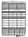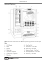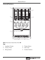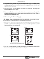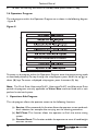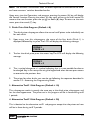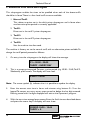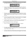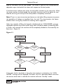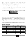
1
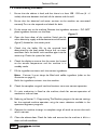
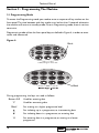
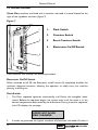
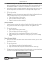
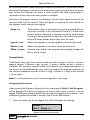
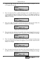
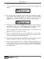
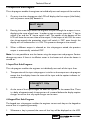
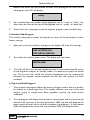
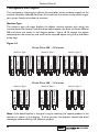
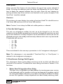
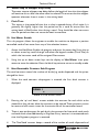
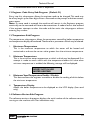
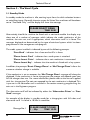
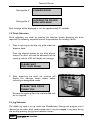
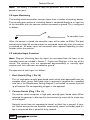
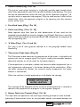
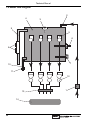
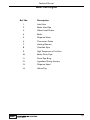
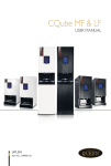
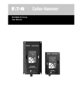
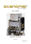
Vision Xtra
Technical Manual
Part No. PR07371000
Revision A
05/04
Technical Manual
Contents
Page No.
Introduction ...................................................................................................2
Important Safeguards ...................................................................................2
Specifications..................................................................................................4
External Features ..........................................................................................5
Internal Features ...........................................................................................6
Section 1 - Installation Procedure ............................................................7
Section 2 - Programming The Machine .................................................10
Section 3 - The Vend Cycle ......................................................................30
Section 4 - Technical Information ...........................................................34
Section 5 - Electrical/Electronic Information .......................................37
Section 6 - Pre-Set Values.........................................................................42
Section 7 - Figures and Diagrams ...........................................................50
The following Symbol is used throughout this Technical Manual:
Safety First! Take care, risk of personal injury.
© Copyright 2003 Crane Merchandising Systems
1
Technical Manual
Introduction
This manual is to be used by authorised personnel involved in installing, commissioning
and servicing the Vision Xtra table-top beverage machine.The technical information
contained within this document is for information only and may be changed without
prior notice. Crane Merchandising Systems accepts no responsibility for any damage
caused to the machine through misinterpretation or misuse of the information
contained in this document.
Upon receipt, carefully examine the machine checking for any damage or
missing/incorrect parts. Any discrepancy must be reported to Crane Merchandising
Systems in writing within three working days.
In accordance with the food hygiene regulations and in compliance with local Public
Health Authorities, it is the responsibility of the operator to keep the machine in a
thoroughly clean condition.
Important Safeguards
When installing or servicing the Vision Xtra, always have this manual available for
quick and easy reference and always follow these basic safety precautions:
1.
Ensure that the machine is situated on a strong horizontal surface, at a convenient
height and in a position where it is not likely to be knocked off.
2.
The mains lead should never trail from the machine and should always be kept
away from hot surfaces and sharp edges.
3.
Allow the machine to cool before handling or moving.
4.
Ensure that the mains electricity supply is isolated before removing any of the
protective panels or undertaking any major servicing.Working on live equipment
should only be undertaken when there is no practical alternative.
5.
When servicing the heater tank. The water can reach a temperature of
approximately 96º C. Water at this temperature can cause severe burns!
6.
Never immerse the machine in water, or any other liquid.This machine must not
be installed in an area where a water jet may be used. Never use a water jet to
clean this machine.
7.
In normal operating conditions the machine should not freeze-up. In the unlikely
event of the machine freezing, turn off the mains water supply, disconnect the
2
Technical Manual
machine from the mains electricity supply and contact Crane Merchandising
Systems for assistance.
8.
Ensure that you are conversant with the ‘Health and Safety at Work and Electricity
at Work Regulations 1989’.
This machine is for indoor use only and because it is a food machine, should be situated
in a clean, hygienic area.
New Vision Xtra Software Overview
With the introduction of enhanced software into the Vision Xtra range the choice
of drinks available from the machines is unlimited, even drinks containing sugar can be
dispensed. This means that machine programming is now different. Essentially each
button can be assigned to any combination of the available products and each whipping
time is now split into 5 equal segments that can be turned on or off individually. If the
machine is running software version NVA01 or later (viewed from within the
engineers program), it is essential that you record the version, ingredient settings and
whipping cycle settings before commencing any work that will reinitialise the machine.
Vision Xtra table-top beverage systems offer customers a complete range of high
quality drinks including Coffee, Cappuccino, Caffe Mocha, Espresso, Chocolate and Tea.
The two models available provide customers with a comprehensive drinks choice of
either 9 or 11 selections.
Outstanding build quality and proven reliability are inherent in Vision Xtra beverage
systems and when combined with quality ingredients, good service and filtered water,
they provide high quality drinks and satisfied customers.
3
Technical Manual
Specifications
Vision Xtra 300
Vision Xtra 400
Height
680 mm
680 mm
Depth
487 mm
487 mm
Width
295 mm
380 mm
Weight
Boiler Capacity
35 kg
50 kg
5.5 Litres
7 Litres
3
4
Number of Canisters
Water Services
(i) Pressure
(ii) Stopcock
Electrical Services
Voltage
Current (2.47kW Heater)
Current (4.85kW Heater)
Current (7.30kW Heater)
Frequency
Optional Extras
100 Kpa (1 Bar) - 800 Kpa (8 Bar)
15 mm BSP from rising main
Vision Xtra 300
Vision Xtra 400
220 - 240 AC or
415 Volts 3 Phase
13 Amp Single Phase
30 Amp Single Phase
415 Volts 3 Phase
50Hz
220 - 240 AC or
415 volts 3 Phase
13 Amp Single Phase
30 Amp Single Phase
415 Volts 3 Phase
50Hz
Vision Xtra 300
Vision Xtra 400
Std. Jug Extension
Height
Weight
75 mm
3 kg
75 mm
5 kg
Tall Jug Extension
Height
Weight
140 mm
6 kg
140 mm
8 kg
Coin/Card Module
Width
Weight
190 mm
8 kg
190 mm
8 kg
Condiments Unit
Height
Width
Depth
704 mm
316 mm
467 mm
704 mm
316 mm
467 mm
Base Cabinets
Height
Width
Depth
Standard
900 mm
457 mm
533 mm
With Side Shelf
900 mm
770 mm
533 mm
Vision 300 + Coin Module
900 mm
573 mm
650 mm
Vision 400 + Coin Module
900 mm
700 mm
650 mm
Vision 300/400 and
Condiment Unit
900 mm
573 mm
650 mm
All weights and dimensions are approximate and are for guidance only.
4
Technical Manual
External Features
Note: Illustration shows Vision Xtra 400 with optional jug extension and coin pod.
Key:
1.
LCD Display
8.
Drip Tray Grill
2.
Door
9.
Coin Return - Coin Pod
3.
Keypad
10. Door Lock - Coin Pod
4.
Door Lock
11. Selection Decals - Coin Pod
5.
Cup Stand - Optional
12. Coin Reject Button - Coin Pod
6.
Jug Extension - Optional
13. Coin Entry - Coin Pod
7.
Drip Tray
5
Technical Manual
Internal Features
1
5
4
3
2
2
1
OFF
ON
3
4
Note: Illustration shows Vision Xtra 400.
Key:
1.
Ingredient Canister
4.
Dispense Spout
2.
Canister Chute
5.
Main Loom
3.
Mixing Stations
6.
Function Switches
6
6
Technical Manual
Section 1 - Installation Procedure
Important! It is essential that engineers responsible for installing,
commissioning and servicing the machine understand the following:
1. The installation and commissioning of the machine should only be carried out by
trained and authorised service engineers.
2. All water and electrical services must be correctly and safely connected.
3. All covers should be replaced correctly and securely and the machine left in a safe
condition.
1.1 Installing the Machine
1. The machine is suitable for indoor use only, sited in an area with a recommended
ambient temperature not below 10º C and not exceeding 30º C.
2. Prior to moving the machine to its location, ensure that there is sufficient access
space available via passageways, stairs, lifts, etc and that the table/counter where the
machine is to be located is strong enough to safely support its weight. (Refer to
Specifications Tables – Page 4).
3. The machine should be located near the appropriate water and electrical services
as detailed in the specification tables.
4. To ensure adequate ventilation, 100 - 150 mm (4 - 6 inches) clearance must be
allowed between the back of the cabinet and the wall.
5. Open the cabinet door. Remove all transit packing and the installation kit from the
machine. Check for visual signs of damage which may have occurred during transit.
Report any problems immediately.
6. The machine should be levelled in both front to back and side to side planes using
the four adjustable levelling feet (6 mm thread). Check for correct alignment using
a spirit level placed on the floor of the machine.
1.2 Connecting the Water Supply
1. The machine should be connected to a 15mm (0.5 inch) rising main water supply
which must conform to local and national regulations and be able to supply water
at a constant pressure of between 100 Kpa (1 Bar) and 800 Kpa (8 Bar).
2. The supply should be fitted with a stopcock to isolate the supply during service.
7
Technical Manual
3. The outlet should be fitted with BSP connections, sited within 1.5 meters of the
vending machine. Connect the flexi-hose to the stopcock. Ensure that the seal
supplied is fitted correctly.
4. Flush the system via the stopcock to remove any impurities that may have
accumulated in the mains supply.
5. Connect the flexi-hose to the machine inlet valve ensuring that the seal supplied is
fitted correctly. Ensure that all water supply fittings are tight.Turn on the supply at
the stopcock and check for leaks.
1.3 Connecting the Electrical Supply
Safety First! THE MACHINE MUST BE EARTHED. ON NO ACCOUNT
SHOULD IT BE EARTHED TO THE WATER SUPPLY PIPE
1. The diagrams, (figures 1 - 4) illustrate the mains lead configuration for the options
available. If the mains lead is damaged in any way, it must be replaced by a special
lead available from the manufacturer.
Figure 1
N
Figure 2
E
L1
L2
N
L3
L1
415V Three-Phase, 7.2kW
(1.5 mm Cable)
Figure 3
N
L1
E
L2
L3
230V Single-Phase, 4.8kW
(4 mm Cable)
Figure 4
E
L2
L1
N
L3
L1
L3
230V Single-Phase, 2.4kW
(1.5 mm Cable)
Machine Connection
For colours etc. see 'Power Circuit' diagram for details
= Element
2. 30 A and 3 phase machines must be hard wired to a suitable mains supply which
has a contact separation of at least 3 mm in all poles.
8
Technical Manual
1.4 Commissioning Procedure
1.
Ensure that the cabinet is level, and that there is at least 100 - 150 mm (4 - 6
inches) clearance between the back of the cabinet and the wall.
2.
Ensure that the electrical and water services to the machine are connected
correctly.Turn on the stopcock and check for leaks.
3.
Fit the waste tray to the machine. Remove the ingredient canisters - DO NOT
place ingredient canisters on the floor.
Figure 5
Open the front door of the machine. Switch on the
mains electricity supply and the electronics on/off switch
(figure 5) located on the switch panel.
4.
5.
Check that the boiler fills to the required level
determined by the level probe. Ensure that no water
overflows from the boiler tank overflow pipe into the
waste tray. Check the system for leaks.
6.
Check the display to ensure that the water has heated
to the correct temperature and the machine is in
standby mode.
7.
Fill the ingredient canisters with the correct ingredients.
Note: Canister 3 must always be filled with coffee ingredient (refer to the
illustration on page 6)
Re-fit the ingredient canisters into the machine.
8.
Check the complete range of machine functions to ensure correct operation.
9.
If a coin mechanism is fitted to the machine, check for correct operation of
mechanism and cash box.
10. Referring to Section 2 - Programming The Machine, program the correct settings
for the required machine operation using the menu selections available in the
operators/engineers programs.
11. Operate the machine through its complete range of vends to ensure that each
vend is correct.
12. Close the cabinet door. Check for leaks and ensure that the machine is left in a
clean and safe condition.
9
Technical Manual
Section 2 - Programming The Machine
2.1 Programming Mode
To access the Programming mode you need to enter a sequence of key strokes on the
front panel.The time between each key stroke must be less than 5 seconds otherwise
the machine will return to standby mode. Once in Programming mode, there is no time
constraint.
Programming mode utilises the front panel keys, as defined in Figure 6, in order to enter
values and commands.
Figure 6
Blank
9 Button Keypad - Vision 300
Blank
During programming the keys are used as follows:
Buttons 0-9
‘C’
‘Blank’
10
Used for entering data
Used for correcting data
For moving to a higher programme level
▲
For indexing up in a programme, or incrementing data
▼
For indexing down in a programme, or entering data
‘A’
For entering data in a programme, or moving to a lower
programme
Technical Manual
2.2 Accessing the Programming Mode
1.
Press the blank key twice followed by the relevant access code - selection button
1 followed by 7 to access the Operators Program or selection button 2 followed
by 1 to access the Engineers Program. Code entry errors may be erased using the
cancel (C) key.
2.
With the correct code entered the title of the first sub-program will be displayed.
In the case of the Operators Program the LCD will display the message:
OPERATIONS
SUB PROGRAM
3.
To step through the sub programs, press either the up (▲) or down (▼) keys.
4.
To access a displayed sub program, press the access (A) key.
5.
If any numerical data parameter is entered, it may be changed in one of two ways:
(a) Pressing the up (▲) or down (▼) keys increases or decreases the number on
each key press.
(b) Keying in the actual digits of the number required. Using this method, the new
number will be displayed in place of the current parameter.
6.
Once the correct number has been entered, press the access (A) key to overwrite
the old parameter with the new number.To retain the old parameter press either
the ‘blank’ or cancel (C) key.
Note: It is not possible to vend a drink in Programming mode.
11
Technical Manual
2.3 Function Switches
Vision Xtra machines are fitted with 4 switches, mounted in a panel located to the
right of the ingredient canisters (figure 7).
Figure 7
1
1
FLUSH
2
Flush Switch
2.
Counters Switch
3.
Reset Counters Switch
4.
Electronics On/Off Switch
2
1.
VIEW
COUNTERS
3
3
4
These switches are used for the following functions:
Electronics On/Off Switch
When switched to off (0), the Electronics on/off switch (4) completely disables the
machine’s electrical functions, allowing the operator to safely carry out machine
cleaning and filling etc.
Flush Switch
1.
The Flush sequence operates automatically and flushes the complete water
system. Before the sequence begins, the system waits until the water is at the
correct temperature determined by the thermostat. During the entire sequence,
the LCD displays the message:
SORRY NOT IN USE
SELF CLEANING
2.
12
In order to guarantee the highest standards of cleanliness, the boiler fill valve is
Technical Manual
disabled, ensuring that the water used in the sequence is delivered at the
optimum temperature to kill any micro-organisms. Each hot water valve and the
corresponding whipper is switched on in sequence for a pre-set flush time.
3.
Once the flush cycle is complete, the boiler refills and when the water is at the
correct temperature, the machine returns to standby mode, ready to vend.
4.
To flush the machine:
Caution: Ensure that the waste tray is empty (and in place) and keep hands away
from the dispensing area whilst the flushing cycle is in operation.
a.
Open the front door of the machine.
b.
Press and release the Flush switch (1).
c.
Empty the waste tray when complete.
Counters Switch
1.
Internal counters monitor the numbers of vends of each drink type, the number
of jug vends, free vends and the weights of each of the ingredients used.
2.
To view the counters:
a.
Open the front door of the machine.
b.
Press and release the Counters switch (2).
c.
Step through the list using the ▲ and ▼ keys on the front panel.
d.
When complete, press the ’Blank’ or cancel (C) key to return to standby
mode.
Reset Counters Switch
1.
Once you have taken note of the values of the internal counters, you can reset
all counters to zero.
2.
To reset the counters:
3.
a.
Enter Programming mode (as described previously).
b.
Open the machine door and press the ‘Reset Counters’ switch (3).
All counters are cleared at this point and the machine gives an intermittent beep
and flashes the message (shown below) to warn the operator:
COUNTERS RESET
13
Technical Manual
4.
To clear the warning and return to standby mode, press cancel (C) key.
2.4 Operators Program
The sub programs within the Operators Program are as shown in the following diagram
- figure 8.
Figure 8
Non Re-settableVend Counters
To access a sub program within the Operators Program, enter the programming mode
as described previously.To step through the sub programs, press either the up (▲) or
down (▼) keys.To access a displayed sub program, press the access (A) key.
Note: The Drink Price, Alternative Tariff 1, Alternative Tariff 2 and Alternative Price
period sub programs are only applicable to Vision Xtra machines fitted with a coin
pod and a coin/card system.
1. Operations Sub-Program
This sub-program allows the operator access to the following functions:
(a) Service: When accessed, this function allows the operator to test vend each
drink selection, for example after carrying out the cleaning procedure.
(b) Self Clean: This function allows the operator to flush the entire mixing
system.
(c) Counter Reset: This function enables the operator to reset all vend/weight
counters to zero.
14
Technical Manual
Note: The ‘self clean’ and ‘counter reset’ functions duplicate the functions of the ‘flush’
and ‘reset counters’ switches described earlier.
Upon entry into the Operations sub program, pressing the access (A) key will display
the ‘Service’ function. Pressing the access (A) key again will carry out the function.To
move to the next function, press the up (▲) or down (▼) keys.To return to the main
menu, press the cancel (C) key.
2. Drink Price Sub-Program (Default = 0)
1.
The drink price sub-program allows the normal tariff prices to be individually set
for each drink.
2.
Upon entry into this sub-program, the name of the first drink (Drink 1) is
displayed, followed by its price.The LCD will display the following message:
DRINK 1
PRICE = 0
3.
To alter the drink price press the access key. The LCD will display the following
message:
DRINK 1
PRICE > 0
4.
The = symbol changes to a > symbol indicating that it is now possible for data to
be changed. Key in the new price using the keypad and when correct press access
to overwrite the previous data.
5.
The prices for other drinks can now be set following the sequence described in
section 2.2 - Accessing the Programming Mode.
3. Alternative Tariff 1 Sub-Program (Default = 10)
This sub-program works in exactly the same way as the drink price sub program and
has the same appearance. The prices set in this program will be in force during tariff
1 periods.
4. Alternative Tariff 2 Sub-Program (Default = 20)
This is identical to the alternative tariff 1 sub-program except that the prices set here
will be in force during tariff 2 periods.
15
Technical Manual
5. Alternative Price Period Sub-Program
This sub-program enables the times to be specified when each of the above tariffs
should be in force.There is a four level tariff structure available:
1. Normal Tariff:
This relates to prices set in the drink price sub-program and in force when
no alternative price period is currently applicable.
2. Tariff 1:
Prices set in the tariff 1 price sub-program.
3. Tariff 2:
Prices set in the tariff 2 price sub-program.
4. Tariff 0:
Sets the machine into free vend.
The machine is factory set to the normal tariff, with no alternative prices available.To
change the tariff period, proceed as follows:1.
On entry into the sub-program the display will show the message:
P1 = 00:00 - 00:00
TARIFF - EVERY DAY
2.
This is an empty price period.To enter a price period (e.g. 10:30 - 15:45,Tariff 2,
Weekends), press access.The display will now read:
START > 00:00
Note: The arrow symbol (>) indicates that it is possible to update the display.
3.
Enter the correct start time in hours and minutes using buttons 0 - 9 on the
keypad.To correct any entry errors, press cancel to delete the last digit entered.
Pressing cancel with no digits displayed will exit to the Operator’s program.
4.
With the start time entered press access. Enter the finish time as described above
and press the access key.The display will now show:
PERIOD 10:30 - 15:45
TARIFF > 0
16
Technical Manual
5.
To set the tariff period, enter a number between 0 and 2 (or use the up (▲) or
down (▼) keys) followed by access.The message will change to:
PERIOD 10:30 - 15:45
TARIFF 2 > EVERYDAY
6.
Using the up (▲) and down (▼) keys, index the day setting between “Every day”,
“Weekdays” and “Weekends”. When the required day setting is displayed, press
the access key to complete the price period data entry. The message on the
display will read:
PERIOD 10:30 - 15:45
TARIFF 2 EVERYDAY
7.
There are a maximum of ten possible price periods available. To enter another
price period, use the up (▲) or down (▼) keys to view the periods until an empty
period is displayed. The new period is entered in the same way as described
previously.
8.
If the start time is entered as being a later time than the finish time, the period
will not be accepted by the machine. If periods overlap, the first overlapping
period in the list will be the one in force until it has finished.
9.
To delete a period, continue as if that period were to be re-programmed, and
when the display is requesting the start time to be entered, press cancel.
6. Non Re-Settable Vend Counters Sub-Program
1.
When this sub-program is entered, the first drink counter is displayed:
DRINK 1
1372
2.
The up (▲) and down (▼) keys enable the counters for each drink to be viewed,
but they cannot be altered using the keypad.These counters can only be reset by
using the “Reset Counters” switch.
3.
There is one vend counter for each drink, plus counters for jug vends, free vends,
total vends and total sales value.The total sales data is displayed in units of 1 penny.
17
Technical Manual
7. Time/Date Sub-Program
The machine maintains a record of the current time and date in 24-hour format.The
date is programmed for leap-year roll-over and should not require adjustment.
To set the time and date, proceed as follows:
1.
The Time/Date sub-program displays the time, date and day of the week.The up
(▲) and down (▼) keys are used for viewing the three different messages.
2.
To view the time, enter the time/date sub-program. The display will show the
message:
TIME = XX:XX
where xx:xx is the current time.
3.
To change the time shown, press the access key.The display will now show:
TIME = XX:XX
SET TIME > 00:00
4.
Enter the correct time in hours and minutes using buttons 0 - 9 on the keypad.
When correct, press access. The time is now set. To view the date, press the up
or down key until the display reads:
DATE = XX:XX:XX
where xx:xx:xx is the current date.
5.
To change the date, press the access key.The display will now show:
DATE = XX:XX:XX
SET DATE > 00:00:00
6.
Enter the correct date using the sequence day, month, year using buttons 0 - 9 on
the keypad.When correct, press access.The date is now set.
7.
To view the day, press the up or down key until the display reads:
DAY = XXXXXXXXX
where xxxxxxxxx is the current day of the week.
18
Technical Manual
8.
To change the day, press the access key.The display will now show:
DAY = XXXXXXXXX
> XXXXXXXXX
9.
Use the up or down arrow keys until the required day is displayed. Press the
access key. The time, date and day are now programmed.
8. Operator Code Sub-Program (Default 17)
Entry into the Operator code sub-program enables the operator code to be changed.
This code may be of any length up to seven digits. Enter a new code at the prompt
and when correct press the access button.
19
Technical Manual
2.4 Engineers Program
The engineers program is entered by pressing the blank key twice and then the relevant
access code - selection button 2 followed by 1. Each time that the engineers program
is entered an ‘Engineer Entry’ counter is incremented. This acts as a security feature
ensuring that the engineers code cannot be accessed without leaving evidence that the
program has been entered.
The sub programs that comprise the engineers program are shown in the following
diagram - figure 9.
Figure 9
Drink Sub-Programs (1 - 9, 0 & C)
Output Test Sub-Programs
Input Test Sub-Program
Keypad Test Sub-Program
Initialise Test Sub-Program
Cup Level Sub-Program
Management Sub-Program
Coin Set Sub-Program
Miscellaneous Settings Sub-Program
Hot Water Enable Sub-Program
Non Resettable Counters Sub-Program
Engineer Code Sub-Program
Temperature Sub-Program
Software Version Sub-Program
1. Drink Sub-Programs
The drink sub programs, numbered 1 - 9, 0 and C allow the engineer to assign drink
menus to each of the selection buttons. Each selection button is configurable to any
mix of the ingredients contained within the canisters, producing drink combinations to
suit customer tastes in a choice of cup, mug or jug sizes.
Within these sub programs it is possible for the engineer to adjust ingredient and water
quantities for each drink selection in order to accommodate different ingredient types
20
Technical Manual
and taste requirements.Additionally, optimised drink presentation is achievable through
control of the whipping time within the drink mixing cycle, enhancing the drink quality
even further. The engineer can select at which stage of the vend cycle product is
dispensed and also how much each product is whipped.
Each drink sub program contains the following sub-sets which relate to each of the
canisters fitted into the machine. These will appear in sequence for each canister as
the engineer scrolls through the program:
Stage = x:
The engineer assigns at which point during the vend product from
the current canister is set to dispense. A value of 1 would cause
product to begin dispensing at the beginning of the vend whereas
a value of 4 causes product to dispense at the end of the vend.A
value of 0 (zero) disables the canister from the vend.
Ingred = xxx:
Allows the engineer to set the ingredient value for each vend.
Water = xxx:
Allows the engineer to set water values for each vend.
Whip = xxxxx:
Controls when and for how long the corresponding whipper will
be run during a vend.
Example Vend
Caffe Mocha with sugar from machine fitted with four canisters. Canister 1 contains
topping; canister 2 contains sugar; canister 3 contains coffee; canister 4 contains
chocolate. The customer requires coffee and chocolate to be dispensed together at
the start of the vend followed by sugar and finally topping.The engineer would set up
the machine to dispense canisters 3 and 4 in stage 1, canister 2 in stage 2 with canister
1 set to stage 3.
Note: It is only possible to vend 3 canisters together in one stage.
Assigning drink menus
Upon entering the Engineers Program the first sub program ‘Drink 1 Sub Program’
will be displayed. This allows the engineer to assign a drink menu to button 1 on the
keypad.The following example details how to assign a chocolate drink to button 1 with
chocolate ingredient contained in canister 4 for a Vision 400 machine.
1.
Press the access key on the keypad.The LCD will display the message:
DRINK 1
Can 1 Stage = x
where x is the current value.
21
Technical Manual
2.
Using the up (▲) and down (▼) arrow keys scroll through the program until the
LCD displays the message:
DRINK 1
Can 4 Stage = x
where x is the current value.
3.
Press the access key.The = symbol will change to the > symbol indicating that it
is now possible to update the display. Press button 1 on the keypad to update the
display followed by access to overwrite the previous value. The LCD will now
display the message:
DRINK 1
Can 4 Stage = 1
4.
Press the up (▲) arrow key to increment to the next sub-menu.This allows the
engineer to set the ingredient value.The LCD displays the message:
DRINK 1
Can 4 Ingred = xxx
where xxx is the current value.
5.
Press the access key and enter the ingredient value using the keypad.Assuming that
the default value for a chocolate drink is entered the LCD will display the message:
DRINK 1
Can 4 Ingred > 55
6.
Press the access key to store the new value. Using the up (▲) arrow key move
to the next sub-menu.This allows the engineer to set the water value.The LCD
displays the message:
DRINK 1
Can 4 Water = xxx
where xxx is the current value.
7.
Press the access key and enter the water value using the keypad. Assuming that
the default value for a chocolate drink is entered the LCD will display the message:
DRINK 1
Can 4 Water > 150
22
Technical Manual
8.
Press the access key to store the new value.
9.
Using the up (▲) arrow key move to the next sub-menu. The LCD displays the
message:
DRINK 1
Can 4 Whip = xxxxx
where xxxxx is the current value.
10. This sub menu allows the engineer to set parameters which control the whipper
motor during the vend cycle. Each number, 1 or 0, represents 20% of the available
whipping time - 1 = on and 0 = off.To set the machine so that the drink is only
whipped at the start of the vend the engineer should set a value as shown:
DRINK 1
Can 4 Whip = 00011
11. Conversely, if the drink is to be whipped at the end of the vend, the engineer
would need to set the value as 11000. To whip the drink throughout the vend a
value of 11111 should be set. A value of 00000 disables the whipper.
When the required value has been entered (using the 1 and 0 buttons on the
keypad), press access to store the new value.
12. Because a chocolate vend does not require product from any of the other
canisters it is necessary for the engineer to scroll through to the relevant menus
and set all of the other canister stage values to 0.
13. For drinks that require more than one product in their menus, follow the above
sequence to program the relevant canister values for each selection.
14. When the correct values for Drink 1 have been entered and stored, press the
cancel (C) key to increment to the next sub program - ‘Drink 2 Sub Program’.
It is now possible to assign a drink menu for selection button 2 using the sequence
described previously.
23
Technical Manual
2. Output Test Sub-Program
This sub-program enables the engineer to individually test each output of the machine.
1.
On entry into the sub-program the LCD will display the first output (Inlet Valve),
with its present state (off) beneath it.
INLET VALVE
off
2.
Pressing the arrow keys allows the engineer to cycle through the outputs in turn,
displaying the name of each one. In order to test an output, press the “1” key to
switch it on, and the “0” key to switch it off. The caption at the bottom of the
LCD will show the current state of the output. If the output is left ‘ON’ for more
than three seconds the protection circuit will switch it ‘OFF’, even though the
display will still indicate that it is ‘ON’.This prevents damage to the motors.
3.
When a different output is selected, or the sub-program exited, the previous
output is automatically switched ‘OFF’.
Note: It is not possible to test the heater using the output test sub-program. Serious
damage may occur if there is insufficient water in the heater tank when the heater is
turned on.
3. Input Test Sub-Program
This sub-program enables the engineer to individually test each of the input lines.
1.
The operation of the input sub-program is similar to the output test sub-program
except that the display shows the name of the input and the caption indicates its’
current state:
COIN INPUT 100p
off
2.
As the state of the input changes, so does the caption on the second line. There
is a delay of approximately three-quarters of a second before the display caption
changes to ensure that any rapid changes can be seen.
4. Keypad Test Sub-Program
The keypad test sub-program enables the engineer to test each key on the keypad to
ensure that it is operating correctly.
1.
24
Whenever a key is pressed, the name of that key will be displayed on the LCD.
Technical Manual
Because the access key was pressed to enter the sub-program, on entry to this
sub-program the LCD will display:
a key
2.
For numerical keys, the number will be displayed, such as “1 key” or “2 key”. For
other keys, the name of the key will be displayed, such as “up key” or “down key”.
3.
To exit from this sub-program into the engineer program, press the blank key.
5. Initialise Sub-Program
The initialise sub-program enables the engineer to return all the parameters to their
factory settings.
1.
Upon entry into the initialise sub-program, the display will show the message:
USE ACCESS KEY
FOR INITIALISATION
2.
To initialise the machine, press access.The display will now show:
INITIALISED
3.
The LCD will flash this message accompanied by an intermittent beep.To return
to the Engineers program or standby mode, it is necessary to press the cancel
key. This ensures that should the initialise sub-program ever be inadvertently
activated, the engineer cannot overlook the fact that the machine has been
initialised.
6. Cup Level Sub-Program
1.
The cup level sub-program allows the amount of water used in each cup vend to
be altered on a percentage basis. This enables different size cups to be used
without having to change each drink ingredient quantity. Jug vends remain
unaffected.
2.
The sub-program will display the cup level as a percentage and this value may be
altered in the same way as all other parameters. 100% cup level will dispense the
exact amount of water set in the drink ingredient sub-programs. A figure below
100% will dispense less water, and a figure above 100% will dispense more.
25
Technical Manual
7. Management Sub-Program
The management sub-program informs the controller which hardware aspects of the
machine have been selected. For Vision Xtra machines this relates to the machine type,
coin system fitted and number of canisters.
Machine Type
The machine type sub menu displays the default machine options with which the
machine leaves the factory.There are three default options for both the Vision 400 and
300 and these are shown in the diagram below - figure 10. To change the option
selected, press the access key and scroll to the required option using the up and down
arrow keys.
Figure 10
Vision Xtra 400 - 4 Canister
Milk/Topping
Sugar
Coffee
Chocolate
Machine Type 3
Milk/Topping
Tea
Coffee
Chocolate
Machine Type 2
Milk/Topping
Coffee 2
Coffee 1
Chocolate
Machine Type 1
Vision Xtra 300 - 3 Canister
Milk/Topping
Sugar
Machine Type 3
Coffee
Milk/Topping
Chocolate
Machine Type 2
Coffee
Milk/Topping
Chocolate
Coffee
Machine Type 1
Note: If the default option is changed it may be necessary to replace product in the
canisters as shown in the diagram. Ensure canisters are emptied, cleaned and dried
thoroughly before refilling with different product.
26
Technical Manual
Coin System
Access into the Coin System sub menu displays the type of coin system selected (if
fitted). To change the selection, press the access key followed by the ‘up’ or ‘down’
keys to display the required selection from the menu. Enter the new selection by
pressing the access key. If the machine is not fitted with a coin system, the option “Free
Vend Only” should be selected.
Canisters
The canisters sub menu displays the number of canisters fitted.This should be set to
4 for Vision 400 machines and 3 for Vision 300 machines.
Note: Canister 3 must always be filled with coffee product as indicated.
8. Coin Set Sub-Program
The coin set sub-program enables the coin set to be changed to suit the coin
mechanism (where fitted) connected to the machine. Although the actual coin set used
by the coin mechanism is totally transparent to the controller, this will ensure that the
displayed message in the standby mode correctly indicates which coins may be entered.
The possible coin sets are:
•
•
•
•
•
1p
1p
1p
5p
5p
-
20p
50p
£1
50p
£1
These are selected in the same way as parameters in the “management sub-program”.
Note: This sub-program is not accessible if “Free Vend Only” or “Card System” is
selected in the management sub-program.
9. Miscellaneous Settings Sub-Program
This sub-program allows various delays and timings to be set which will affect all of
the drinks in the machine. The defaults for these settings are shown in Section 6 - Pre
Set Values.
1.
Water Start To Ingredient Start Delay
The water start to ingredient start delay defines the time between water starting
to be dispensed and the ingredient starting to be dispensed. If ingredient reaches
the mixing bowl before the water, it may stick to the sides of the bowl.This delay
ensures that ingredient is always dispensed into a bowl already containing water.
27
Technical Manual
2.
Water Stop To Whipper Stop Delay
The water stop to whipper stop delay defines the length of time that the whipper
will continue to run after the water valve has closed.This ensures that the whipper
operates whenever there is water in the mixing bowl.
3.
Flush Time
This setting is the period of time that a valve is opened during a flush cycle. It is
generally set slightly higher than the period set for a vend to ensure that the
mixing bowl is filled further than during a vend. Care should be taken to ensure
that the period set does not cause the bowl to overflow.
10. Hot Water Enable
This sub program allows the engineer to enable the machine to dispense a portion
controlled vend of hot water from any of the selection buttons.
1.
Access the Hot Water Enable sub program and press the access key. Using the up
or down arrow key scroll through and select the keypad number (Drink No.) to
which the hot water vend will be assigned. Press access.
2.
Using the up or down arrow keys set the display to ‘Hot Water’ then press
access to store the selection. Press the blank key twice to return to standby mode.
11. Non-Resettable Counters Sub-Program
The vend counters record the number of drinks/jug vends dispensed and the prices
charged for them.
1.
When the vend counters sub-program is entered, the first drink counter is
displayed:
DRINK 1
x
where x is the current value.
2.
Pressing the ‘up’ and ‘down’ arrows enables the counters for each drink to be
viewed, but they do not allow the counters to be altered.These counters cannot
be reset and will remain intact for the service life of the controller board.
3.
There is one vend counter for each drink, plus counters for free vends, total vends
and total drink value.Additionally, an ‘Engineer Entry’ counter is incremented each
time the Engineers program is accessed.
4.
The ‘Total Vend’ counter keeps a record of the number of vends dispensed and
28
Technical Manual
is incremented each time a drink is dispensed.
12. Engineer Code Entry Sub-Program (Default 21)
Entry into this sub-program allows the engineer code to be changed. This code may
be of any length up to seven digits. Enter a new code at the prompt and when correct,
press access.
Note: If a zero code is entered, the machine will remain in the Engineers program
continually, so the zero code will have to be overwritten. A code of zero is also entered
if the engineer attempts to alter the code and then exits the sub-program without
entering any number.
13.Temperature Sub-Program
The temperature sub-program allows the parameters controlling boiler temperature
and temperature display to be altered.There are four parameters which may be altered.
1.
Maximum Temperature
This is the maximum temperature to which the water will be heated and
maintained at and must be set to a value greater than the minimum temperature.
2.
Minimum Temperature
This is the minimum water temperature at which a drink may be dispensed. If an
attempt is made to vend a drink with the temperature below this value when
minimum temperature is enabled, the following message will be displayed:
SORRY NOT IN USE
WATER HEATING
3.
Minimum Vend Temperature Enable / Disable
This feature allows the engineer to enable or disable the vending of drinks below
the minimum temperature.
4.
Temperature Display
Allows the boiler temperature to be displayed on the LCD display (free vend
only).
14. Software Version Sub-Program
The software version sub-program displays the serial number of the software version
running on the machine and is for information only.
29
Technical Manual
Section 3 - The Vend Cycle
3.1 Standby Mode
In standby mode the machine is idle, awaiting input from the drink selection buttons
or switch/key inputs. Generally the coin system for Vision Xtra machines will have been
set to “Free Vend Only” and the display will show the message:
PLEASE SELECT DRINK
TIME 10:30
Alternatively, should the machine be fitted with a coin/card module the display may
show one of a number of messages which indicate the credit mechanism of the
machine, the coin set, and if appropriate, which alternative tariff is in force. The
messages displayed are determined by the type of coin/card system which has been
programmed in the management sub-program.
The credit system installed is indicated by one of the following prompts:
‘Free Vend’ - indicates that a free vend tariff is in force.
‘Please Insert Card’ - indicates that a card system is attached.
‘Please Insert Coins’ - indicates that a coin mechanism is connected.
‘Please Insert Key’ - indicates that the machine is fitted with a key system.
In addition, the prompts ‘Exact Change Please’ or ‘No Change Given’ inform the
customer whether change is available.
If the mechanism is set to acceptor, the ‘No Change Given’ message will always be
displayed. If the mechanism is set to change-giver, the prompt will depend upon how
full the change tubes are. For more information, please refer to the manual supplied
with the change-giver.The coin set accepted by the coin mechanism is displayed.This
is pre-set in the controller and is outlined in the section covering programming the
coin set in the Engineers program.
The alternative tariff will be indicated by either the ‘Alternative Prices’ or ‘Free
Vend’ messages.
An example of the display in standby mode for a change-giver with full tubes, and
alternative tariff 1 in force at 10:30 a.m. would be:
Message No. 1
30
PLEASE INSERT COINS
1 - 50p
TIME 10:30
Technical Manual
Message No. 2
CHANGE GIVEN
Message No. 3
ALTERNATIVE PRICES
NOW AVAILABLE
Each message will be displayed in turn for approximately 21⁄2 seconds.
3.2 Drink Selection
Drink selections are made by pressing the selection button displaying the drink
required.The following sequence outlines the procedure for vending a drink.
1. Place a cup/mug on the drip tray grille under the
dispense head.
Press the selection button for the drink of your
choice. The drink will now be delivered into the
cup/mug and the LCD will display the message:
PLEASE WAIT
FOR YOUR DRINK
2. After dispensing the drink, the machine will
display the message shown below before
returning to background mode:.
PLEASE TAKE DRINK
THANK YOU
Remove the cup/mug from the machine.Add milk
etc as required.
3.3 Jug Selection
The coffee jug vend is set up within the Miscellaneous Settings sub program and is
identical to the other drink vends except that it may be stopped at any point during
the vend by pressing the Jug vend selection button.
31
Technical Manual
Ingredient is dispensed in two equal quantities throughout the vend. To vend a jug
selection, proceed as follows:
1.
Lift up the cup stand (if fitted) and place the jug
on the grille under the dispense head.
2.
Press the coffee-jug selection button. The drink
will be delivered into the jug. Press the jug
selection button again to stop the vend.
3.
Remove the jug and lower the cup stand to
horizontal position.
3.4 Example Vend
The following description outlines the sequence of events required to vend a chocolate
drink with the whipper set to run throughout the complete vend cycle.
1.
Machine is in standby mode.
2.
Customer presses chocolate selection button.
3.
The chocolate water valve is opened.
4.
The chocolate whipper motor is started.
5.
The controller waits for the time specified in the water to ingredient start delay.
6.
The chocolate ingredient motor is started.
7.
The cup level percentage is used to calculate the chocolate water time.
8.
The chocolate ingredient time is read from the drink settings.
9.
The controller waits until each time period has elapsed to turn off the motor and
valve.
10. The controller waits for the time specified in the water to whipper stop delay
after the valve has closed.
11. The whipper is switched off.
12. The machine returns to standby mode.
The timing diagram (figure 11), viewed in conjunction with the flow chart (figure 12)
on the following page, are used to illustrate the ‘example vend’.
32
Technical Manual
Figure 11
Chocolate water time x cup level
CHOCOLATE
VALVE
Water to whipper delay
CHOCOLATE
WHIPPER
Water to ingredient start delay
CHOCOLATE
INGREDIENT
MOTOR
Chocolate ingredient time
TIME (NOT TO SCALE)
Figure 12
USER SELECTS
DRINK
OPEN CHOCOLATE
WATER VALVE
HAS
WATER TIME
BEEN REACHED AND
VALVE STILL
ON?
YES
SWITCH OFF
CHOCOLATE
VALVE
YES
SWITCH OFF
CHOCOLATE
WHIPPER
YES
SWITCH OFF
CHOCOLATE
MOTOR
START CHOCOLATE
WHIPPER MOTOR
NO
HAS WATER
TO INGREDIENT TIME
ELAPSED?
NO
HAS
WATER-WHIP TIME
BEEN REACHED AND
WHIPPER STILL
ON?
NO
YES
START CHOCOLATE
INGREDIENT MOTOR
HAS
INGREDIENT TIME
BEEN REACHED AND
MOTOR STILL
ON?
NO
HAVE ALL
OUTPUTS BEEN
SWITCHED
OFF?
NO
YES
RETURN TO
BACKGROUND MODE
33
Technical Manual
Section 4 - Technical Information
4.1 Water Services
The mains water supply provides water for the boiler.Water enters at the rear of the
machine through a solenoid operated inlet valve which opens or closes the water
supply as required.
4.2 Hot Water System
1. Depending upon the machine configuration, water is heated in the boiler to the
required temperature by a heating element rated at either 2.4 Kilowatts (1
element), 4.8 Kilowatts (2 elements) or 7.2 Kilowatts (3 elements).
2. The mains voltage required for the element(s) is switched by a solid state relay,
controlled by the vending machine controller via an analogue signal transmitted by
the thermistor probe.
3. The water level inside the boiler is controlled by a water level probe. When the
water drops below the required level, the controller board operates the mains
water inlet valve until the required water level is restored.
4. A series of control valves are mounted on the outside of the boiler.These supply
heated water to the mixing stations where ingredients are added to make the drink.
4.3 Water Supply
1. Should the inlet valve fail (or mains water supply be disabled), the controller board
will detect a fault after the inlet valve “open” signal has been active for 2 minutes
or the required water level has not been reached.
2. At this point the keypad will be disabled, all outputs from the controller board
(including the heater element) will be switched off and the display will show the
message:
SORRY NOT IN USE
LOW WATER
4.4 Ingredient Dispense
1. The ingredients required for making up a drink are contained in ingredient canisters
and are dispensed by means of a motor driven auger located in the base of each
canister.
34
Technical Manual
2. The amount of product dispensed by each canister is controlled by the vending
machine controller and may be adjusted via timing constants set in the engineers
program.
3. The required ingredients for each vend are delivered to a mixing bowl, where they
are blended with hot water by a controllable, high speed whipper prior to discharge
at the dispense head.
4. To ensure a free flow of ingredient powder and granules, it is essential that they
are kept completely dry. This is achieved by extracting steam from the mixing
system using an extract fan. The electrical supply for the extract fan is 110 Volts
AC.
Note! The fan runs continuously whilst there is live mains electricity supply to the
machine.
4.5 Coin and Card/Key Systems
Vision Xtra machines may be equipped with coin or card/key validation systems using
Mars protocol ‘A’ housed in a separate module mounted on the side of the machine.
The coin or card/key system informs the vending machine controller of the amount
of credit which has been deposited into the vending machine.
1. Change Giver
1. The Change Giver communicates with the vending machine controller through a
serial communication interface. It will validate a coin and if accepted, send a signal
to the vending machine controller indicating the total amount of money which has
been tendered since the last vend.
2. Once sufficient credit has been accumulated a vend will be permitted.The vending
machine controller will communicate to the change giver the actual price of the
drink dispensed. The change giver will return any change due to the customer,
provided the change tubes contain coinage above a pre-set level.
2. Card/Key System
1. The card system fitted to the machine communicates with the vending machine
controller using the same principle as the change giver.
2. The card system informs the vending machine controller of the amount of credit
on the customer's card. If there is sufficient credit for the selected drink, the
vending machine controller permits a vend and informs the card system of the
amount of credit to be taken from the card. The new balance will then be re35
Technical Manual
written onto the customer's card.
3. Coin Acceptor
1. The coin acceptor is an electronic coin system which can validate up to six different
coin or token denominations and gives an appropriate pulsed output if a coin has
been recognised.
2. The outputs are one line per coin from open collector NPN transistors referenced
to 0 Volts. Each output is normally off and is switched on for between 80 and 200
milliseconds on acceptance of a corresponding coin.
3. The vending machine controller has separate inputs for each coin line. When
sufficient money has been deposited, the vending machine controller will permit a
vend.
4. The acceptor will not dispense change.
4. Coin Blocker
Both coin systems have a coin blocking facility. On machines fitted with a coin acceptor,
a logic “low” level on the input disables any coin acceptance. For machines fitted with
a change-giver, the appropriate command from the vending machine controller will have
the same effect.
Note! For full information and programming instructions for all of these systems,
please refer to the user manual supplied with the validation system.
36
Technical Manual
Section 5 - Electrical/Electronic Information
Vision Xtra machines utilise a 220 - 240 Volt, 13 Amp single phase or 30 Amp three
phase electricity supply.This is fed via a mains filter, 25 Amp solid state relays and high
temperature cut-outs to the heating element(s) located in the boiler.
5.1 Mains Filter
The mains filter prevents spurious voltages reaching the power supply on the I/O and
controller boards and other sensitive components within the machine.
5.2 25 Amp Relays
The 25 Amp relays switch 240 Volts to the heater element(s) when required as detailed
in Section 4.1 Water Services.
5.3 High Temperature Cut-Out
The high temperature cut-outs, located in the heater tank overflow, sense the
temperature of any water in the overflow pipe.
1. Should the boiler over heat due to a control failure, the water will boil over into
the overflow pipe. The high temperature of the water will cause the cut-outs to
operate, switching off the electrical supply to the heater element(s).
2. With the electrical supply disconnected and the control fault rectified, the cut-outs
can be reset by the small push button.
5.4 Transformer
To accommodate for any variations in the mains voltage, the transformer has three
separate input tappings - 240 Volts, 230 Volts and 220 Volts. The mains supply is taken
directly to the primary side of the transformer.
There are three output voltages from the transformer.They are as follows:1. 24 Volt Output
The 24 Volt supply is used to power the coin mechanism or card/key system fitted
to the machine.
2. 12 - 0 - 12 Volt Outputs
1. These outputs are connected to the I/O board where they are rectified to produce
an unregulated DC supply.
2. The I/O board regulates the DC supply to produce two separate 5 volt supplies
37
Technical Manual
for the logic circuits and the triac drivers.
3. The unregulated DC supply is also connected to the controller board where it is
regulated to 5 and 12 Volts to power the logic circuits and level probe respectively.
3. 110 Volt Output
1. The 110 Volt live supply is connected via a 6.3 Amp fuse to the common terminals
of all the valves, solenoids and motors in the machine.
2. The extractor fan is connected across the 110 Volt supply and operates
continuously.
3. The 0 Volt side of the 110 Volt supply connects directly to the triac drivers, each
of which is connected in turn to one of the 110 Volt components. To operate a
component, the triac is switched on. This completes the 110 Volt circuit to that
component.
4. Each triac is operated by an encoded signal sent along the serial communication
link from the controller board.
5. Because the triac common is connected to 0 Volt and a live feed is present on them
at all times, the 110 Volt components may be considered to be ‘Neutral Switched’.
6. Each triac may be individually tested using the ‘Engineers Output Test Program’.
Safety First! Care must be taken when servicing the machine as 110 Volts is
always present at the triacs when the mains is switched on.
5.6 Serial Communications Link
Communication between the controller and I/O boards is achieved by a two wire serial
data bus using the I2C protocol. A screened cable is used to reduce any radiated
electrical interference and thus prevent any data transfer failures.
5.7 System Memory
Three types of memory are used on the controller board:
1. EPROM Memory - holds the controller operating program.
2. Data Memory - used by the controller during operation.
3. Battery Backed Memory - stores all parameters set by the operator or
engineer when the mains power is switched off.
38
Technical Manual
Note: The battery is intended to keep the parameter data intact for a minimum
period of ten years.
5.8 Input Monitoring
The vending machine controller monitors inputs from a number of switching devices.
The normally open contact of a switching device is connected directly to an input line
of the controller, with the common contact connected to ground. This is configured
as follows:
To controller input
When the contact is closed, the controller input will be taken to 0 Volts. The level
control circuit, boiler fill and thermostat are monitored continually when the machine
is switched on. All other inputs are monitored when required, depending on their
function within the machine.
5.9 Individual Input Functions
Note: Diagrams illustrating how the inputs are connected from the loom to the
controller board are included in Section 7 - Figures and Diagrams at the rear of this
manual. The switching units are represented diagrammatically as normally open
switches with their commons connected to ground.
The operation of each input is as follows:
1. Flush Switch (Plug 1, Pin 10)
This is a single pole, normally open, biased switch, which when operated flushes the
complete water system. Each boiler valve is operated in sequence for a specified
time (set in the ‘Miscellaneous Settings Program’) and ‘rattled’ to remove any build
up of limescale.The corresponding whipper is also operated.
2. Counter Switch (Plug 1, Pin 11)
The counter switch comprises a single pole, normally open, biased switch. When
operated the operator is able view the vend counters by means of the arrow keys
on the keypad.
Normally to exit from this sequence the ‘cancel’ or ‘blank’ key is pressed. A ‘timeout’ feature ensures that the controller automatically reverts to standby mode if a
key is not pressed after a period of thirty seconds.
39
Technical Manual
3. Counter Reset (Plug 1, Pin 14)
The counter reset switch comprises a single pole, normally open, biased switch,
which when operated will reset all the counters available to the operator. This input
can only be accessed from within the main part of the “operator’s program” (i.e.
not from within an operators sub-program). Only the vend counters, which can be
viewed from within the operator’s program, or by operating the view counters
switch, will be reset.
4. Free Vend Input (Plug, 1 Pin 18)
5. Coin Lines (Plug 1, Pins 19 - 25)
Seven separate input lines (one for each denomination of coin which can be
accepted) are provided from the coin acceptor unit (if fitted). Each input is normally
high and will be pulsed low for between 80 and 200 milliseconds on acceptance of
the corresponding coin.
6. ‘0’ Volts (Plug 1, Pins 33 and 34)
This plug is the ‘0’ volts (ground) referred to in the paragraph headed “Input
Monitoring”.
7. Thermistor Probe Input (Plug 35)
The Thermistor probe measures the temperature of the water in the boiler and
converts this into an analogue signal.This signal is used by the controller board to
determine whether or not to switch on the heater element.
If the temperature in the boiler is below the maximum boiler temperature (set in
the “temperature sub-program”), the heater element will be switched on. When
the boiler temperature reaches the maximum boiler temperature, the heater
element is switched off.
When the machine is initially powered up, it will display the message:
SORRY NOT IN USE
WATER HEATING
This message will be displayed until the minimum vend temperature is reached, as
defined in the temperature sub-program in the engineer’s program.
8. Heater Tank Level Control (Plug 1, Pin 36)
This input does not operate on the same logic switching principle as those outlined
previously. A level control circuit on the controller board is connected between the
40
Technical Manual
body of the boiler and the level probe. This sends a signal to the microprocessor
dependent upon the level of the water with respect to the level probe.
If the level circuit indicates low water, the controller switches on the inlet valve. When
the water reaches the level probe, the controller continues to fill the boiler for two
seconds, ensuring that the tip of the level probe is completely immersed.
Note: There is a two minute time-out feature on the boiler filling sequence to preven
the possibility of leakage or overflow from the tank. This also prevents the heater
element from running dry should the incoming water supply fail.
After sixty seconds of filling, the keypad is disabled and the “LOW WATER” message
displayed to prevent any further water being taken. Should the boiler still be filling after
a further sixty seconds, the machine will be completely disabled as illustrated by the
flow chart - Figure 13.
Figure 13
LEVEL PROBE INPUTS
"LOW" SIGNAL
SWITCH ON
MAIN INLET VALVE
NO
HAS VALVE
BEEN ON FOR
60 SECONDS?
NO
IS THE WATER
AT THE CORRECT
LEVEL?
YES
YES
DISPLAY LOW WATER
MESSAGE AND
DISABLE KEYPAD
SWITCH OFF VALVE AND
RETURN TO STANDBY MODE
NO
HAS VALVE
BEEN ON FOR
120 SECONDS?
NO
IS THE WATER
AT THE CORRECT
LEVEL?
YES
YES
DISABLE MACHINE
If the water level in the boiler is low when the machine is switched on, the “LOW
WATER” message will be displayed. The boiler will fill as described above and when
the correct water level is reached, the machine will enter “Standby” mode.
41
Technical Manual
Note: In a situation of low mains water pressure and a very low boiler level at power
up, the boiler may require more than two minutes to fill. This will cause the machine
to be disabled before the boiler is full. Under these circumstances, the machine can
be switched ‘off’ and then ‘on’ again to reset the boiler time-out.
9. Electronic Waste Probe (Plug 1, Pins 37 and 38)
A level control circuit on the controller board is connected between two probes
located in the waste tray. A signal is sent to the micro-processor depending on the
level of the water in respect to the level probe.
If the level circuit indicates a high waste water level, the LCD will show the message:SORRY NOT IN USE
WASTE TRAY FULL
The machine will remain in this state until the waste tray has been emptied.
Section 6 - Pre-Set Values
The information contained within the following section illustrates the pre-set values
for all of the parameters which may be changed within both the operators and
engineers programs. The values shown are those with which the machine leaves the
factory. Should the Initialise sub program be activated, these values will be restored
into the controller memory.
The pre-set values for parameters accessed via the Operators Program are shown in
the following tables:
Alternative Price Periods
Period
One
Two
Three
Four
Five
Six
Seven
Eight
Nine
Ten
42
Start Time
End Time
Tariff
Day Type
00:00
00:00
00:00
00:00
00:00
00:00
00:00
00:00
00:00
00:00
00:00
00:00
00:00
00:00
00:00
00:00
00:00
00:00
00:00
00:00
-
Everyday
Everyday
Everyday
Everyday
Everyday
Everyday
Everyday
Everyday
Everyday
Everyday
Technical Manual
Vend Counters
Drink Type
Time and Date
Counter Pre-Set
Parameter
Drink 1
0000000
Time (24 Hr. clock)
Drink
Drink
Drink
Drink
Drink
Drink
Drink
Drink
Drink
Drink
0000000
0000000
0000000
0000000
0000000
0000000
0000000
0000000
0000000
0000000
Date
Day of the Week
2
3
4
5
6
7
8
9
0
C
Setting
00:00
1:1:90
Monday
Drink Prices
Drink Type
Normal Tariff
Tariff One
Tariff Two
1
2
3
4
5
6
7
8
0
0
0
0
0
0
0
0
10
10
10
10
10
10
10
10
20
20
20
20
20
20
20
20
Drink 9
Drink 0
Drink C
0
0
0
10
10
10
20
20
20
Drink
Drink
Drink
Drink
Drink
Drink
Drink
Drink
The pre-sets for the parameters found in the Engineers Program are shown in the
following tables:
Cup Level
Miscellaneous Settings
Parameter
Setting
Water to Ingredient Start Delay
Water to Whipper Stop Delay
Flush Water Time
15
40
100
Cup Level
100%
Management
Coin Set
1 - 50p
Coin Set
Coin System
Free Vend Only
N.B. The vend counters when viewed from within the Engineers Program cannot be
altered from their original settings.
43
44
Drink 5
Drink 6
Cappuccino
Caffe Latte
Can 1 STAGE
1
Can 1 STAGE
2
INGR
25
INGR
30
WATER 80
WATER 80
WHIP 11111
WHIP 11111
Can 2 STAGE
0
Can 2 STAGE
0
INGR
0
INGR
0
WATER
0
WATER
0
WHIP 00000
WHIP 00000
Can 3 STAGE
2
Can 3 STAGE
1
INGR
20
INGR
18
WATER 40
WATER 40
WHIP 00000
WHIP 00000
Drink 9
Drink 0
Drink C
Drink 7
Espresso
Doppio Espresso
Chocolate
Caffe Mocha
Can 1 STAGE
0
Can 1 STAGE
0
Can 1 STAGE
0
Can 1 STAGE
1
INGR
0
INGR
0
INGR
0
INGR
17
WATER
0
WATER
0
WATER
0
WATER 36
WHIP 00000
WHIP 00000
WHIP 00000
WHIP 11111
Can 2 STAGE
0
Can 2 STAGE
0
Can 2 STAGE
1
Can 2 STAGE
1
INGR
0
INGR
0
INGR
55
INGR
55
WATER
0
WATER
0
WATER 150
WATER 70
WHIP 00000
WHIP 00000
WHIP 11111
WHIP 11111
Can 3 STAGE
1
Can 3 STAGE
1
Can 3 STAGE
0
Can 3 STAGE
2
INGR
30
INGR
50
INGR
0
INGR
14
WATER 40
WATER 60
WATER
0
WATER 15
WHIP 11111
WHIP 11111
WHIP 00000
WHIP 00000
Drink 1
Drink 2
Drink 3
Black Coffee
White Coffee
Hot Water
150
Can 1 STAGE
0
Can 1 STAGE
1
Can 1 STAGE
INGR
0
INGR
12
INGR
WATER
0
WATER 80
WATER
WHIP 00000
WHIP 00011
WHIP
Can 2 STAGE
0
Can 2 STAGE
0
Can 2 STAGE
INGR
0
INGR
0
INGR
WATER
0
WATER
0
WATER
WHIP 00000
WHIP 00000
WHIP
Can 3 STAGE
1
Can 3 STAGE
1
Can 3 STAGE
INGR
18
INGR
18
INGR
WATER 80
WATER 40
WATER
WHIP 00000
WHIP 00000
WHIP
Technical Manual
Drink Pre-Sets
3 Canister - Machine Type 1
Drink 9
Drink 0
Drink C
Drink 7
Coffee Jug
Caffe Latte
Double Espresso
Chocomilk
Can 1 STAGE
0
Can 1 STAGE
1
Can 1 STAGE
0
Can 1 STAGE
2
INGR
0
INGR
30
INGR
0
INGR
17
WATER
0
WATER 80
WATER
0
WATER 55
WHIP 00000
WHIP 11111
WHIP 00000
WHIP 11111
Can 2 STAGE
0
Can 2 STAGE
0
Can 2 STAGE
0
Can 2 STAGE
1
INGR
0
INGR
0
INGR
0
INGR
55
WATER
0
WATER
0
WATER
0
WATER 85
WHIP 00000
WHIP 00000
WHIP 00000
WHIP 11111
Can 3 STAGE
1
Can 3 STAGE
1
Can 3 STAGE
1
Can 3 STAGE
0
INGR
36
INGR
18
INGR
50
INGR
0
WATER 320
WATER 70
WATER 160
WATER
0
WHIP 00000
WHIP 10000
WHIP 11111
WHIP 00000
Drink 1
Drink 2
Drink 3
Drink 5
Drink 6
Black Coffee
Cappuccino
Chocolate
Espresso
Caffe Mocha
Can 1 STAGE
0
Can 1 STAGE
1
Can 1 STAGE
0
Can 1 STAGE
0
Can 1 STAGE
1
INGR
0
INGR
25
INGR
0
INGR
0
INGR
17
WATER
0
WATER 80
WATER
0
WATER
0
WATER 36
WHIP 00000
WHIP 11111
WHIP 00000
WHIP 00000
WHIP 00011
Can 2 STAGE
0
Can 2 STAGE
0
Can 2 STAGE
1
Can 2 STAGE
0
Can 2 STAGE
55
INGR
0
INGR
0
INGR
55
INGR
0
INGR
70
WATER
0
WATER
0
WATER 150
WATER
0
WATER
0
WHIP 00000
WHIP 00000
WHIP 11111
WHIP 00000
WHIP 11111
Can 3 STAGE
1
Can 3 STAGE
2
Can 3 STAGE
0
Can 3 STAGE
1
Can 3 STAGE
2
INGR
18
INGR
20
INGR
0
INGR
30
INGR
14
WATER 160
WATER 70
WATER
0
WATER 80
WATER 30
WHIP 10000
WHIP 11111
WHIP 00000
WHIP 11111
WHIP 11111
Technical Manual
3 Canister - Machine Type 2
45
46
Drink 5
Drink 6
White Coffee
White Coffee with Sugar
Can 1 STAGE
1
Can 1 STAGE
1
INGR
12
INGR
12
WATER 80
WATER 40
WHIP 00011
WHIP 00011
Can 2 STAGE
0
Can 2 STAGE
1
INGR
0
INGR
22
WATER
0
WATER 40
WHIP 00000
WHIP 11111
Can 3 STAGE
1
Can 3 STAGE
1
INGR
18
INGR
18
WATER 40
WATER 40
WHIP 00000
WHIP 00000
Drink 9
Drink 0
Drink C
Drink 7
Caffe Latte
Espresso
Espresso with Sugar
Cappuccino
Can 1 STAGE
2
Can 1 STAGE
0
Can 1 STAGE
0
Can 1 STAGE
1
INGR
30
INGR
0
INGR
0
INGR
25
WATER 80
WATER
0
WATER
0
WATER 80
WHIP 00000
WHIP 00000
WHIP 00000
WHIP 11111
Can 2 STAGE
0
Can 2 STAGE
0
Can 2 STAGE
1
Can 2 STAGE
0
INGR
0
INGR
0
INGR
10
INGR
0
WATER
0
WATER
0
WATER 15
WATER
0
WHIP 00000
WHIP 00000
WHIP 11111
WHIP 00000
Can 3 STAGE
1
Can 3 STAGE
1
Can 3 STAGE
1
Can 3 STAGE
2
INGR
18
INGR
30
INGR
30
INGR
20
WATER 40
WATER 40
WATER 32
WATER 40
WHIP 00000
WHIP 11111
WHIP 11111
WHIP 00000
Drink 1
Drink 2
Drink 3
Black Coffee
Black Coffee with Sugar Hot Water
150
Can 1 STAGE
0
Can 1 STAGE
0
Can 1 STAGE
INGR
0
INGR
0
INGR
WATER
0
WATER
0
WATER
WHIP 00000
WHIP 00000
WHIP
Can 2 STAGE
0
Can 2 STAGE
1
Can 2 STAGE
INGR
0
INGR
22
INGR
WATER
0
WATER 80
WATER
WHIP 00000
WHIP 11111
WHIP
Can 3 STAGE
1
Can 3 STAGE
1
Can 3 STAGE
INGR
18
INGR
18
INGR
WATER 80
WATER 40
WATER
WHIP 00000
WHIP 00000
WHIP
Technical Manual
3 Canister - Machine Type 3
0
0
0
00000
0
0
0
00000
1
18
80
00000
0
0
0
00000
1
25
80
11111
2
20
80
00000
0
0
0
00000
0
0
0
00000
Drink 1
Black Coffee
Can 1 STAGE
INGR
WATER
WHIP
Can 2 STAGE
INGR
WATER
WHIP
Can 3 STAGE
INGR
WATER
WHIP
Can 4 STAGE
INGR
WATER
WHIP
Drink 7
Cappuccino
Can 1 STAGE
INGR
WATER
WHIP
Can 2 STAGE
INGR
WATER
WHIP
Can 3 STAGE
INGR
WATER
WHIP
Can 4 STAGE
INGR
WATER
WHIP
1
12
80
00011
0
0
0
00000
1
18
40
00000
0
0
0
00000
0
0
0
00000
1
30
80
11111
0
0
0
00000
0
0
0
00000
Drink 3
Hot Water
150
Can 1 STAGE
INGR
WATER
WHIP
Can 2 STAGE
INGR
WATER
WHIP
Can 3 STAGE
INGR
WATER
WHIP
Can 4 STAGE
INGR
WATER
WHIP
Drink 8
Drink 9
Cappuccino - Large
Espresso
Can 1 STAGE
1
Can 1 STAGE
INGR
31
INGR
WATER 100
WATER
WHIP 11111
WHIP
Can 2 STAGE
2
Can 2 STAGE
INGR
25
INGR
WATER 100
WATER
WHIP 00000
WHIP
Can 3 STAGE
0
Can 3 STAGE
INGR
0
INGR
WATER
0
WATER
WHIP 00000
WHIP
Can 4 STAGE
0
Can 4 STAGE
INGR
0
INGR
WATER
0
WATER
WHIP 00000
WHIP
Drink 2
White Coffee
Can 1 STAGE
INGR
WATER
WHIP
Can 2 STAGE
INGR
WATER
WHIP
Can 3 STAGE
INGR
WATER
WHIP
Can 4 STAGE
INGR
WATER
WHIP
Drink 0
Chocolate
Can 1 STAGE
INGR
WATER
WHIP
Can 2 STAGE
INGR
WATER
WHIP
Can 3 STAGE
INGR
WATER
WHIP
Can 4 STAGE
INGR
WATER
WHIP
0
0
0
00000
0
0
0
00000
0
0
0
00000
1
55
150
11111
Drink C
Caffe Mocha
Can 1 STAGE
INGR
WATER
WHIP
Can 2 STAGE
INGR
WATER
WHIP
Can 3 STAGE
INGR
WATER
WHIP
Can 4 STAGE
INGR
WATER
WHIP
Drink 4
Drink 5
White Coffee - Large
Caffe Latte
Can 1 STAGE
1
Can 1 STAGE
INGR
15
INGR
WATER 100
WATER
WHIP 00011
WHIP
Can 2 STAGE
0
Can 2 STAGE
INGR
0
INGR
WATER
0
WATER
WHIP 00000
WHIP
Can 3 STAGE
1
Can 3 STAGE
INGR
23
INGR
WATER 50
WATER
WHIP 00000
WHIP
Can 4 STAGE
0
Can 4 STAGE
INGR
0
INGR
WATER
0
WATER
WHIP 00000
WHIP
1
17
36
11111
2
14
30
00000
0
0
0
00000
0
0
0
00000
2
30
80
11111
1
18
80
00000
0
0
0
00000
0
0
0
00000
Drink 6
Caffe Latte - Large
Can 1 STAGE
2
INGR
38
WATER 100
WHIP 11111
Can 2 STAGE
1
INGR
23
WATER 100
WHIP 00000
Can 3 STAGE
0
INGR
0
WATER
0
WHIP 00000
Can 4 STAGE
0
INGR
0
WATER
0
WHIP 00000
Technical Manual
4 Canister - Machine Type 1
47
0
0
0
00000
0
0
0
00000
1
18
160
10000
0
0
0
00000
0
0
0
00000
1
8
160
00000
0
0
0
00000
0
0
0
00000
Drink 1
Black Coffee
Can 1 STAGE
INGR
WATER
WHIP
Can 2 STAGE
INGR
WATER
WHIP
Can 3 STAGE
INGR
WATER
WHIP
Can 4 STAGE
INGR
WATER
WHIP
Drink 7
Tea
Can 1 STAGE
INGR
WATER
WHIP
Can 2 STAGE
INGR
WATER
WHIP
Can 3 STAGE
INGR
WATER
WHIP
Can 4 STAGE
INGR
WATER
WHIP
48
1
25
80
11111
0
0
0
00000
2
20
70
11111
0
0
0
00000
Drink 8
Hot Water
150
Can 1 STAGE
INGR
WATER
WHIP
Can 2 STAGE
INGR
WATER
WHIP
Can 3 STAGE
INGR
WATER
WHIP
Can 4 STAGE
INGR
WATER
WHIP
Drink 2
Cappuccino
Can 1 STAGE
INGR
WATER
WHIP
Can 2 STAGE
INGR
WATER
WHIP
Can 3 STAGE
INGR
WATER
WHIP
Can 4 STAGE
INGR
WATER
WHIP
Drink 9
Coffee Jug
Can 1 STAGE
INGR
WATER
WHIP
Can 2 STAGE
INGR
WATER
WHIP
Can 3 STAGE
INGR
WATER
WHIP
Can 4 STAGE
INGR
WATER
WHIP
Drink 3
Chocolate
Can 1 STAGE
INGR
WATER
WHIP
Can 2 STAGE
INGR
WATER
WHIP
Can 3 STAGE
INGR
WATER
WHIP
Can 4 STAGE
INGR
WATER
WHIP
0
0
0
00000
0
0
0
00000
1
36
320
00000
0
0
0
00000
0
0
0
00000
0
0
0
00000
0
0
0
00000
1
55
150
11111
Drink 0
Caffe Latte
Can 1 STAGE
INGR
WATER
WHIP
Can 2 STAGE
INGR
WATER
WHIP
Can 3 STAGE
INGR
WATER
WHIP
Can 4 STAGE
INGR
WATER
WHIP
Drink 4
Chocomilk
Can 1 STAGE
INGR
WATER
WHIP
Can 2 STAGE
INGR
WATER
WHIP
Can 3 STAGE
INGR
WATER
WHIP
Can 4 STAGE
INGR
WATER
WHIP
1
30
80
11111
0
0
0
00000
1
18
70
10000
0
0
0
00000
2
17
55
00011
0
0
0
00000
0
0
0
00000
1
55
85
11111
Drink C
Double Espresso
Can 1 STAGE
INGR
WATER
WHIP
Can 2 STAGE
INGR
WATER
WHIP
Can 3 STAGE
INGR
WATER
WHIP
Can 4 STAGE
INGR
WATER
WHIP
Drink 5
Espresso
Can 1 STAGE
INGR
WATER
WHIP
Can 2 STAGE
INGR
WATER
WHIP
Can 3 STAGE
INGR
WATER
WHIP
Can 4 STAGE
INGR
WATER
WHIP
0
0
0
00000
0
0
0
00000
1
38
160
11111
0
0
0
00000
0
0
0
00000
0
0
0
00000
1
30
80
11111
0
0
0
00000
Drink 6
Caffe Mocha
Can 1 STAGE
INGR
WATER
WHIP
Can 2 STAGE
INGR
WATER
WHIP
Can 3 STAGE
INGR
WATER
WHIP
Can 4 STAGE
INGR
WATER
WHIP
1
17
36
11111
0
0
0
00000
2
14
30
11111
1
55
70
11111
Technical Manual
4 Canister - Machine Type 2
0
0
0
00000
0
0
0
00000
1
18
80
00000
0
0
0
00000
2
30
80
11111
0
0
0
00000
1
18
40
00000
0
0
0
00000
Drink 1
Black Coffee
Can 1 STAGE
INGR
WATER
WHIP
Can 2 STAGE
INGR
WATER
WHIP
Can 3 STAGE
INGR
WATER
WHIP
Can 4 STAGE
INGR
WATER
WHIP
Drink 7
Caffe Latte
Can 1 STAGE
INGR
WATER
WHIP
Can 2 STAGE
INGR
WATER
WHIP
Can 3 STAGE
INGR
WATER
WHIP
Can 4 STAGE
INGR
WATER
WHIP
Drink 8
Drink 9
Caffe Latte with Sugar
Espresso
Can 1 STAGE
2
Can 1 STAGE
INGR
30
INGR
WATER 40
WATER
WHIP 11111
WHIP
Can 2 STAGE
2
Can 2 STAGE
INGR
15
INGR
WATER 40
WATER
WHIP 11111
WHIP
Can 3 STAGE
1
Can 3 STAGE
INGR
18
INGR
WATER 40
WATER
WHIP 00000
WHIP
Can 4 STAGE
0
Can 4 STAGE
INGR
0
INGR
WATER
0
WATER
WHIP 00000
WHIP
Drink 2
Drink 3
Black Coffee with Sugar White Coffee
Can 1 STAGE
0
Can 1 STAGE
INGR
0
INGR
WATER
0
WATER
WHIP 00000
WHIP
Can 2 STAGE
1
Can 2 STAGE
INGR
22
INGR
WATER 80
WATER
WHIP 11111
WHIP
Can 3 STAGE
1
Can 3 STAGE
INGR
18
INGR
WATER 40
WATER
WHIP 00000
WHIP
Can 4 STAGE
0
Can 4 STAGE
INGR
0
INGR
WATER
0
WATER
WHIP 00000
WHIP
0
0
0
00000
0
0
0
00000
1
30
40
11111
0
0
0
00000
1
12
80
00011
0
0
0
00000
1
18
40
00000
0
0
0
00000
Drink 0
Drink C
Espresso with Sugar
Chocolate
Can 1 STAGE
0
Can 1 STAGE
INGR
0
INGR
WATER
0
WATER
WHIP 00000
WHIP
Can 2 STAGE
1
Can 2 STAGE
INGR
10
INGR
WATER 15
WATER
WHIP 11111
WHIP
Can 3 STAGE
1
Can 3 STAGE
INGR
30
INGR
WATER 32
WATER
WHIP 11111
WHIP
Can 4 STAGE
0
Can 4 STAGE
INGR
0
INGR
WATER
0
WATER
WHIP 00000
WHIP
Drink 4
Drink 5
White Coffee with Sugar Cappuccino
Can 1 STAGE
1
Can 1 STAGE
INGR
12
INGR
WATER 40
WATER
WHIP 00011
WHIP
Can 2 STAGE
1
Can 2 STAGE
INGR
22
INGR
WATER 40
WATER
WHIP 11111
WHIP
Can 3 STAGE
1
Can 3 STAGE
INGR
18
INGR
WATER 40
WATER
WHIP 00000
WHIP
Can 4 STAGE
0
Can 4 STAGE
INGR
0
INGR
WATER
0
WATER
WHIP 00000
WHIP
0
0
0
00000
0
0
0
00000
0
0
0
00000
1
55
150
11111
1
25
80
11111
0
0
0
00000
2
20
40
00000
0
0
0
00000
Drink 6
Cappuccino with Sugar
Can 1 STAGE
1
INGR
25
WATER 40
WHIP 11111
Can 2 STAGE
1
INGR
15
WATER 40
WHIP 11111
Can 3 STAGE
2
INGR
20
WATER 40
WHIP 00000
Can 4 STAGE
0
INGR
0
WATER
0
WHIP 00000
Technical Manual
4 Canister - Machine Type 3
49
Technical Manual
Section 7 - Figures and Diagrams
7.1 Input Circuit
Black/White
Grey/Orange
Black/White
Purple/Yellow
Black/White
Yellow/Red
Black/White
White/Grey
Black/White
Blue/Black
Black/White
Yellow/Black
Black/White
Pink/Orange
Black/White
Green/White
Black/White
White/Black
Black/White
Blue/Yellow (1)
Black/White
White/Green
Black/White
Blue/Green (1)
Black/White
Black/White
Black/White
Heater
Tank
Probe
Orange/Green
Yellow/Green
Blue/Green
Yellow/Green (1)
Probe
50
Probe
1
2
3
4
5
6
7
8
9
10
11
12
13
14
15
16
17
18
19
20
21
22
23
24
25
26
27
28
29
30
31
32
33
34
35
36
37
38
Flush Switch
Counter Switch
Counter Reset
Free Vend Key
Coin Input 1p
Coin Input 2p
Coin Input 5p
Coin Input 10p
Coin Input 20p
Coin Input 50p
Coin Input £1
Waste Tray Switch
'0' Volts
'0' Volts
Heater Tank Probe
Heater Tank
Electronic Waste Probe
Electronic Waste Probe
Technical Manual
7.2 Output Circuit
110V live (Red)
PL 11
Purple/Orange 1
Purple/White 2
Pink 3
Orange 4
White 5
Orange/Pink 6
Grey 7
Grey/Green 8
Grey/Blue 10
Grey/Pink 11
Blue 12
Blue/Yellow 13
Blue/Pink 14
Green 15
Green/Purple 16
Green/Pink 17
20
21
22
23
24
25
26
27
30
31
32
33
34
35
36
+5V
Purple/Black 37
38
Red/Green 39
Red/Orange 40
V
V
V
W
V
M
M
W
V
M
W
V
M
W
Inlet Valve
Canister 1 Valve
Canister 2 Valve
Canister 1 Whipper
Canister 4 Valve
Canister 2 Motor
Canister 1 Motor
Canister 2 Whipper
Canister 3 Valve
Canister 4 Motor
Canister 3 Whipper
Hot Water Valve
Canister 3 Motor
Canister 4 Whipper
Solid State Relay
Solid State Relay
Blocker
Solid State Relay
51
Technical Manual
7.3 Power Circuit
I/O Board
Controller Board
PL 10
PL 3
1
2
3
Red
Blue
Screen
1
2
18V DC
0V DC
Reset
4
6
9
Red/White
Red/Black
Pink/Black
-5V DC
10
Yellow/Red
1
2
3
4
5
1
7
Red/Pink
White/Purple
I2C DataBus
PL 9
PL 2
+
-
LCD Backlight
Solid State Relay (3)
Brown 4
Brown (7)
Heater
Fuse (3)
Brown (10)
Brown (13)
High Temp.
Cut-out (3)
Blue (4)
2.375 kW
Heater Element (3)
Solid State Relay (2)
Brown 3
Brown (6)
Heater
Fuse (2)
Brown (12)
High Temp.
Cut-out (2)
Blue (3)
2.375 kW
Heater Element (2)
Solid State Relay (1)
3-Phase
Filter
Brown 2
Brown (5)
Heater
Fuse (1)
L3
L2
Blue (1)
L1
Brown
N
E
Brown (9)
Brown (8)
Brown (11)
High Temp.
Cut-out (1)
Blue (2)
2.375 kW
Heater Element (1)
Blue (1)
Blue
Green/Yellow
4 Amp
Lamp
(240V)
240V
Blue/Grey
24V
Coin Mech.
Grey/Orange
Coin Mech.
230V
Orange/White
220V
12V
PL9, Pin 2
Pink/White
PL9, Pin 5
Lightbox
Common Fuse
(See Page 53)
PL9, Pin 3
Grey/Black
Red
Motors,Valves etc.
Common
Fuse
0V
Black
Lamp
(0V)
52
Fan
0 Volt Common
on I/O Board
Technical Manual
7.4 Lightbox Circuit
1
Black
2
From
Transformer
White
Green/Yellow
Black
3
4
White
Ref. No.
1.
2.
3.
4.
Description
1A Fuse
Ballast
Tube
Starter
53
Technical Manual
7.5 Water Flow Diagram
2
4
3
8
5
6
9
7
10
11
12
13
14
54
1
Technical Manual
Water Flow Diagram
Ref. No.
Description
1.
Inlet Valve
2.
Boiler Inlet Pipe
3.
Water Level Probe
4.
Boiler
5.
Dispense Valves
6.
Thermistor Probe
7.
Heating Element
8.
Overflow Pipe
9.
High Temperature Cut-Outs
10.
Boiler Drain Pipe
11.
Drain Pipe Bung
12.
Ingredient Mixing Stations
13.
Dispense Head
14.
Waste Tray
55
Technical Manual
7.6 Route Diagram
Power from
Transformer
Power for Controller
PL 10
PL 9
I/O Board
PL 11
Blocker Relay
Triac Outputs
Triac Neutrals
Boiler Level Control
Control Inputs
0 Volts
PL 1
Controller
Board
PL 3
PL 9
PL 4
2
I C Link
CPU
PL 5
PL 6
PL 2
Keypad
Coin Mech.
Communications
Temperature
Probe
56
Display
Pipsmore Park, Bumpers Farm Industrial Estate,
Chippenham,Wiltshire SN14 6NQ
Tel: +44 (0)1249 444807 Fax: +44 (0)1249 444819
Email: [email protected]
Website: www.cranems.co.uk