1
Harsen®
Manual
GU620A
Genset Controller
HM1006ER3
Manual HM1006ER3
The Interpretation of the Symbol
The Interpretation of the Symbol:
WARNING:
A WARNING indicates a potentially hazardous situation which, if not
avoided, could result in death, serious personal injury or property damage.
CAUTION:
A CAUTION indicates a potentially hazardous situation which, if not avoided,
could result in damage to equipment or property.
NOTE:
A NOTE provides other helpful information that does not fall under the
warning or caution categories.
Harsen®
I
Manual HM1006ER3
The interpretation of the Symbol
WARNING:
Read this entire manual pertaining to the work to be performed before
installing, operating, or servicing this controller. Practice all plant and safety
instructions and precautions. Failure to follow instructions can cause
personal injury and/or property damage.
The engine or other type of prime mover should be equipped with an
overspeed shutdown device to protect against runaway or damage to the
prime mover with possible personal injury, loss of life, or property damage.
The overspeed shutdown device must be totally independent of the prime
mover control system. An over temperature or low pressure shutdown device
may also be needed for safety, as appropriate.
CAUTION—BATTERY CHARGING
To prevent damage to a controller that uses an alternator or battery-charging
device, make sure the charging device is turned off before disconnecting the
battery from the system.
Controllers contain static-sensitive parts. Observe the following precautions
to prevent damage to these parts:
Do not disassemble the rear back of controller and touch the components or
conductors on a printed circuit board.
Harsen®
II
Manual HM1006ER3
History
History
No.
Rev.
Date
Editor
Validation
Changes
1
HM1006ER1
2010.11.1
Chen
P.L
Increase Expansion Relay Menus
2
HM1006ER2
2011.6.10
Chen
P.L
Increase Oil-P Stop and Coolant
Stop Menus.
3
HM1006ER3
2012.3.12
Chen
P.L
Increase Oil-P Delay and Coolant
Delay Menus.
、
Harsen®
III
Manual HM1006ER3
Contents
Contents
1. Description…………………………………………………………………………………..………..…..
1
2. The Outline Dimension Drawings and Controller Wiring…………………………….…………..
2
3. Panel Operation…………………………………………………………………………….………...…..
5
4. Control and Operation Instruction………………………………………………………………..…..
7
5. Measure and Display Data………………………………………………………………….………….. 14
6. Warning and Shutdown Alarm…………………………………………………………….………….. 15
7. Parameters Setting…………………………………………………………………………………..….. 21
8. Installation Guide………………………………………………………………………………………... 46
9. LCD displays and Menu System…………………………………………………………………..….. 55
10. Technical Specification……………………………………………………………………………..….. 59
Harsen®
IV
Manual HM1006ER3
Description
1. Description
GU620A is a new generation Automatic control module for single Genset, which adopts bran-new
outline configuration, focus on the requirements of customers, and perfectly improves the performance
of controller. It fully meets the auto control requirements of different kinds of Genset for user or special
assembly factory.
The module also monitors and protects the engine, indicating operational status, fault conditions and
metering on the front panel LCD and LED’s.
True RMS measure of voltage and current.
Multi-Language menu.
128 x 64 pixel LCD display.
4 analog inputs for kinds of optional sensors that can be used for measuring oil pressure, coolant
temperature, fuel level and so on; parameters can be configured by user.
More outputs of configurable auxiliary control relays.
More configurable isolated digital inputs.
Buttons on control panel are used for selecting control modes, starting and stopping the operating
procedure, displaying data and modifying the parameters. LED indicators are used for indicating
the operation mode of controller and the running status of Genset, and LCD displays each
measuring parameter and status.
Flexible equipped with RS485, RS232 and USB, realizing remote monitor; or communicated with
PC, fully realizing functions of remote signaling, telemetering and remote control, can read and set
the running parameters of controller.
With GPRS-DTU or Ethernet-DTU for remote communication instead of RS485, RS232, or USB
port for remote communication.
Optional CANbus, read and control the parameters for ECU engine.
All connections of the controller are by secure plug and socket, for ease and convenience to connect,
move, maintain and replace the device.
Optional ultra low temperature function, the ambient temperature is from -40 ℃ to 70 ℃.
This manual is only suitable for GU620A Automatic control module, user must carefully read
this manual first.
Harsen®
Page 1/60
Manual HM1006ER3
The Outline Dimension Drawings and Controller Wiring
2. The Outline Dimension Drawings and Controller Wiring
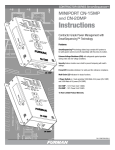
2.1 Following Details:
Module Dimensions
W192mm×H144mm
Panel Cutout
W174mm×H126mm
Thickness
D56mm (without connection)
Harsen®
Page 2/60
Manual HM1006ER3
The Outline Dimension Drawings and Controller Wiring
2.2 Terminal Connections:
Pin no.
1
2
3
4
5
6
7
8
9
10
11
12
13
14
15
16
17
18
19
20
21
22
23
24
25
26
27
28
29
30
31
32
33
34
35
36
37
38
39
40
Function Description
GEN. VL1-N input
GEN. VL2-N input
GEN. VL3-N input
GEN. Neutral
Not used
Not used
Not used
Not used
Not used
I1 Gen current input (S1)
I2 Gen current input (S1)
I3 Gen current input (S1)
Comm. port for current inputs (S2)
LOP sensor
HET sensor
Sensor com. port
Auxiliary sensor #1
Auxiliary sensor #2
Common port for relay outputs
Fuel solenoid relay output
Start relay output
Relay output 3 (GCB close/open)
Relay output 4
Relay output 5
Relay output 6
charger excitation power output
Relay output 7
Relay output 7
Configurable digital input signal 1
Configurable digital input signal 2
Configurable digital input signal 3
Configurable digital input signal 4
Configurable digital input signal 5
Configurable digital input signal 6
Configurable digital input signal 7
Magnetic pick-up signal (+)
Common for configurable inputs
and magnetic pick-up signal (-)
Battery supply (+B)
Battery supply (-B)
Ground
Signal
0-346Vac
0-346Vac
0-346Vac
0-5A
0-5A
0-5A
0-5A
<1KΩ
<1KΩ
Resistance type sensor (<1KΩ)
Resistance type sensor (<1KΩ)
N.O. contact, 16A/30Vdc
N.O. contact, 16A/30Vdc
N.O. contact, 3A/30Vdc, configurable (1)
N.O. contact, 3A/30Vdc, configurable (2)
N.O. contact, 3A/30Vdc, configurable (3)
N.O. contact, 3A/30Vdc, configurable (4)
if not used, do not connect to negative
N.O. contact, 3A/30Vdc, configurable (5)
low level is active
low level is active
low level is active
low level is active
low level is active
low level is active
low level is active
1-70Vac
12V/24V (8-35Vdc continuous)
Dim
1mm²
1mm²
1mm²
1mm²
2.5mm²
2.5mm²
2.5mm²
2.5mm²
2.5mm²
2.5mm²
2.5mm²
2.5mm²
2.5mm²
2.5mm²
2.5mm²
2.5mm²
1mm²
1mm²
1mm²
1mm²
1mm²
1mm²
1mm²
1mm²
1mm²
1mm²
1mm²
1mm²
1mm²
1mm²
2 core
shield
2.5mm²
2.5mm²
2.5mm²
NOTE:
Relay output 3 is configured as GCB close/open relay when default
setting, however it can be reconfigured by user if required.
Harsen®
Page 3/60
Manual HM1006ER3
The Outline Dimension Drawings and Controller Wiring
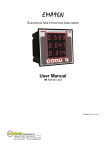
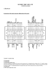
2.3 Typical Wiring Diagram
A fuse with the rating of 1A shall be provided external to the equipment.
Harsen®
Page 4/60
Manual HM1006ER3
Panel Operation
3. Panel Operation
The operation panel consists of 3 sections: LCD display indicating measurement parameters, LED
indicator for common failure, and push buttons for Genset and selection of control modes.
LCD with 128*64 pixels can display multi-line data in the same time. LCD also has a backlight so that
the operator can clearly read information day or night. After pressing any button the backlight will
automatically turn off after a preset time.
The LCD display and its control push buttons provide a friendly operational interface for the operator to
easily control the Genset, read information and parameter setting.
3.1 Control buttons and LED
Function Description
Tag
Scroll Button
Scroll menu for parameters display / enter into or exit parameters
setting by pressing and holding this button for 2sec.
MUTE / Lamp Test Button
When failure occurs, alarm buzzer sounds. Pressing mute button will
mute the sound. LCD displays mute icon. Press it again will clean
mute function, buzzer continues to sound. Press and hold this button
for 2sec, all LEDs illuminate simultaneously.
AUTO Mode Button / LED / “+” Value Increase
The push button is used for selecting “auto mode”. When the controller
is running in AUTO mode, the LED above the button is illuminated.
The activation and deactivation of the “remote start signal input”
controls the starting and stopping of the Genset.
When in parameters setting mode, this button is used to increase
value / scroll down menu.
MAN Mode Button / LED / “-” Value Decrease
The push button is used for selecting “manual mode”. When the
controller is running in MANUAL mode, the LED above the push button
is illuminated. The Start and Stop push buttons control the starting of
the Genset.
When in parameters setting mode, this button is used to decrease
value / scroll up menu.
TEST Mode Button / LED / “√
√” Confirm Parameters Configure
The push button is used for selecting “test mode”. When controller is
running in TEST mode, the LED above the push button is illuminated,
the controller starts the generator simulating the activation of “remote
start signal”.
When in parameters setting mode, this button is used to enter into
submenu / confirm modification.
Harsen®
Page 5/60
Manual HM1006ER3
Panel Operation
START Button / LED / Return
The push button is used for manually start the Genset. When controller
is running in MANUAL mode, press this button to start the generator.
When in parameters setting mode, this button is used to return.
STOP / RESET Button / “→
→” Move Setting
The Push button is used for manually stops the Genset. No matter
what mode the controller is running, press and hold this button for
2sec to stop the generator, the mode of the controller will be default to
“MAN” mode automatically from “AUTO” or “TEST” mode and the
generator will be shut down after cool down period, during the cool
down period if you press and hold this button for 2sec again, the
generator will be shut down immediately.
If failure occurs, press this button, the shutdown alarm lockout can be
cleared.
When in parameters setting mode, this button is used to move to next
parameters setting position.
C/O Button
It is used to close/open the switch of Gen when controller is running in
MANUAL mode.
Shutdown Alarm (FAILURE) LED
The LED will illuminate permanently when shutdown alarm occurs.
Pre-alarm (WARNING) LED
The LED will illuminate permanently when pre-alarm occurs.
GEN. Normal LED
Gen. normal LED will illuminate after both voltage and frequency of the
Gen. reach loading voltage and frequency.
GCB Closed LED
LED will illuminate when GCB is closed and power supplied by Gen,
LED will flash when GCB failure occurs.
Harsen®
Page 6/60
Manual HM1006ER3
Control and Operation Instruction
4. Control and Operation Instruction
The controller has 3 modes: AUTO, MANUAL and TEST.
4.1 Operation Modes Setting:
Operation
Description
Press and hold the “AUTO” button for 2sec, the LED above the button
is illuminated; the controller is running in “AUTO” mode.
Press and hold the “MAN” button for 2sec, the LED above the button is
illuminated; the controller is running in “MAN” mode.
Press and hold the “TEST” button for 2sec, the LED above the button
is illuminated; the controller is running in “TEST” mode.
NOTE:
Only 1 mode can be selected from above 3 modes.
Controller keeps the states for the previous mode when changing the
operation mode, then implements the control procedure of the next mode
according to the present states.
4.2 AUTO Control Sequence:
The controller is running in “AUTO” mode.
Generator Auto Start Sequence:
NOTE:
To achieve remote start, one of configurable inputs must be defined as
remote start signal.
The Start delay timer is activated, when it times out, the preheat relay output is energised (if preheat
function selected), the timer starts. When it times out, the fuel relay output is energised, and operates
the fuel solenoid of the engine. After 300ms delay, the start relay output is energised, the start motor
engages and begins to crank. When the engine speed reaches the crank cutout RPM, the start relay
output is de-energised and the safety-on delay starts. When the safety-on times out, if the controller
detects that the parameters of the Genset such as voltage, frequency, oil pressure, coolant temperature
are normal, and no other failure is detected this indicates the Genset has successfully started and
running normally. The LCD displays the Genset Measurement Parameters.
Harsen®
Page 7/60
Manual HM1006ER3
Control and Operation Instruction
When Generator is running normally, Gen. Normal LED illuminates, the timer for GEN. ON delay is
activated, when it times out, GCB close/open relay closes, then the transfer switch switches on Gen.
The Gen Aux. Switch’s contact feeds back a signal to a configurable input on the controller. GCB
closed LED illuminates.
NOTE:
When remote signal is active, the start-delay timer is activated, if remote
start signal is inactive during this period, the start delay timer terminates
immediately, the controller terminates the starting procedure, then
recovers to the original standby status.
During cranking or idle period, if the remote start signal is inactive, the
controller stops the start procedure, then recovers to the original standby
status.
Under any conditions, GEN. ON delay only can be started after Safety-on
Delay times out.
NOTE:
The start motor will power off while cranking if there are one of the
following conditions occur:
A. The generator’s frequency reaches the preset value (configurable
cranking cutout value);
B. The AC engine speed reaches crank cutout value;
C. Generator’s Voltage reaches the crank cutout value (optional);
D. Charger voltage reaches crank cutout value (optional);
E. Cutout P-delay time’s up (optional);
F. Cranking time’s up.
Controller can not implement crank procedure in one of following
conditions:
A. The generator’s frequency reaches the preset value (configurable
cranking cutout value);
B. The AC engine speed reaches crank cutout value;
C. Generator’s Voltage reaches the crank cutout value (optional);
D. LOP switch is opened or oil pressure is higher than crank cutout
value (optional).
CAUTION:
If magnetic pickup is not used, to avoid damage to the start motor please
make sure the generator’s voltage is higher than the measurable value of
controller while cranking, since the crank cutout signal is sensed from the
generator voltage and frequency.
NOTE:
Above control procedure, assumes that one of configurable inputs has
been configured as Gen Aux. Switch Closed and connects the switch’s
N.O. Aux. contact signal to this port. If you do not configure an input as
Gen Aux. Switch Closed, then the GCB closed LED illuminates is only
an indication that the GCB close/open relay should have been closed.
If you have selected idle function, the idle relay will be closed at the same time as the crank relay is
closed, the idle timer will begin counting down after successful crank, when it times out, the idle relay
opens, other procedure is the same as above.
Harsen®
Page 8/60
Manual HM1006ER3
Control and Operation Instruction
NOTE:
Controller will not detect under voltage, under frequency, under speed, and
charge failure during idle period.
Repeat Crank: During the crank period, if the engine can not ignite and controller will not output start
signal during crank rest. Once crank rest timer times out the start relay energises once again and will
attempt to start engine again. The above procedure will be repeated until engine successfully ignites or
reaches the preset number of crank attempt.
If any shutdown alarm occurs during crank, controller will stop cranking immediately, and the Genset only can be
restarted after clearing the failure and reset.
Start Failure: When the procedure above repeats again and again and reaches the preset number of
crank attempt, the crank relay output is then de-energised. The failure LED illuminates and the LCD
displays Fail to Start.
CAUTION:
If Fail to Start occurs, operator must check the whole Genset system to
find out failure reason, only after clearing the failure can press “ STOP /
RESET” button to relieve fault lock out status, and restart the Genset.
Generator shutdown sequence:
When remote start signal is inactive, GCB close/open relay de-energises, Gen is off load, the timer for
cool down is activated, when it times out, the fuel relay de-energises, generator stops and recovers to its
standby status.
NOTE:
When remote start signal is inactive, directly enter into cooldown status if
none relay is defined as GCB close/open relay output.
Stop Failure: When cool down times out, the fuel relay opens and the timer for Stop delay begins. If the
controller detects that the voltage of the generator or oil pressure or the speed of engine is greater than
the cutout values or LOP switch is open, when it times out, the failure LED illuminates and the LCD
displays Fail to stop.
NOTE:
After stop failure, the controller will not energise the crank relay output if
the failure has not been removed and the controller reset.
Harsen®
Page 9/60
Manual HM1006ER3
Control and Operation Instruction
4.3 MAN control Sequence:
The controller is running in “MANUAL” mode.
Generator starting sequence:
Pressing “START” button the fuel relay is energised, and operates the fuel solenoid of engine, After
300ms delay, the start relay output is energised, the start motor engages and begins to crank, When the
engine speed reaches the crank cutout RPM, the start relay output is de-energised and the safety-on
delay starts. When the safety-on times out, if the controller detects that the parameters of the Genset
such as voltage, frequency, oil pressure, coolant temperature are normal, and no other failure is
detected this indicates the Genset has successfully started and running normally. The LCD displays the
Genset Measurement Parameters.
After both voltage and frequency of generator respectively reached the loading value, the Gen. Normal
LED illuminates, the GCB close/open relay will not be closed automatically.
Press the “C/O” button of Gen to close the Gen switch manually, then Gen is on load, the Gen Aux.
switch’s contact feeds back the signal to a configurable input on our controller, GCB closed LED
illuminates. Press the “C/O” button of Gen again to open the Gen switch manually, the Gen is off load, the
GCB closed LED is turned off at the same time.
NOTE:
When the controller is running in “MANUAL” mode, the Gen must be
normal, or the “C/O” button of Gen will be disabled.
Generator stopping sequence:
Press “STOP” button, GCB close/open relay opens, the generator is off load, the cool down timer starts,
when it times out , the fuel relay is de-energised, then the fuel solenoid opens immediately, generator
stops and goes to standby status.
If press “STOP” button again during cool down period, generator stops immediately without cool down time.
4.4 TEST control Sequence:
When the Controller is running in “TEST” mode means it simulates remote start signal is activated. There
are two kinds of “TEST” modes, one is “Test with load”, another is “Test without load”, and they can be
selected through parameter setting.
Test with load: GCB close/open relay will be closed after the generator is started successfully and
running normally, then Gen will be on load.
Test without load: GCB close/open relay will not be closed after the generator is started successfully and
running normally, the Mains remain on load.
Harsen®
Page 10/60
Manual HM1006ER3
Control and Operation Instruction
4.5 The start and stop sequence of engine whose fuel solenoid is N. O. type:
There are two kinds of fuel solenoids for an engine, one is N.C. type, the valve of this solenoid is closed
when the engine is in standby and it can be opened by switching on power; another is N.O. type, the
valve of this solenoid is opened when engine is in standby and it can be closed by switching on power. All
control sequences above are for N.C. type.
Start control sequence for N.O. type:
During the starting sequence the fuel relay of controller will not energise, fuel solenoid is off power, fuel
solenoid is normally open so no signal required for fuel solenoid to activate.
Stop control sequence for N.O. type:
During the controller’s stop sequence, the fuel relay energises, fuel solenoid is on power, the fuel solenoid
closes the fuel valve and the engine begins to stop. After a delay (same as Stop delay) fuel relay deenergises, disconnecting the supply from the fuel solenoid.
Other control sequences same as engine whose fuel solenoid is N. C. type.
4.6 Idle function:
For idle function configure one of the configurable outputs as idle.
Refer to the flow chart 4.10 for start and stop for idle control flows.
NOTE:
Controller will not detect under voltage, under frequency, under speed, and
charge failure during idle period.
4.7 Preheat function:
For Preheat function, configure one of the configurable outputs as Preheat, the controller has 5
selectable preheat control modes as below:
Mode 1 — during preheat time, preheat relay output energises.
Mode 2 — during preheat time, preheat relay output energises until the successful ignition.
Mode 3 — during preheat time, preheat relay output energises until safety-on delay times out.
Mode 4 — one of the configurable inputs is defined as Preheat, preheat relay output energises when this
configurable input is active, and de-energises when configurable input is inactive.
Mode 5 —the A-sensor 2 use is defined as Preheat, preheat relay output energises when the temperature
falls below the Preheat ON value, and de-energises until the temperature reaches the Preheat
OFF value.
For preheat mode 1 to 3, please refer to the flow chart 4.10 for start and stop for Preheat control flows.
For preheat mode 4 to 5, Preheat function is active immediately when the controller is switched on power.
During crank period, the Preheat relay output will not energise in any of above modes.
Harsen®
Page 11/60
Manual HM1006ER3
Control and Operation Instruction
4.8 The function of forcing start:
Reason to add this function to the controller is that when the engine under abnormal conditions, e.g. the
battery voltage is too low or ambient temperature is too low, or generator only outputs voltage at a high
speed when magnetic pick-up is not used, the Genset cannot be started successfully when it
implements the build-up cranking process of controller. There are 2 methods to solve these conditions
in the controller:
First method: when controller is running in “MANUAL” mode, normally the crank time will not exceed the
pre-set value, but you can press “START” button and hold without changing the related parameters until
it has started, the crank time depends on the holding time on the button. Safety-on timer begins after it
has successfully started. The other processes and protections are the same as for a normal start.
Second method: when controller is running in “MANUAL” mode, configure the “EX. Crank permit” as
“1”, shown as schematic below, a PB switch is externally mounted to control cranking. Close PB switch,
engine cranks, when the speed reaches 150RPM or generator voltage output is not less than AC 20V if
magnetic pick-up is not used, then controller functions are triggered, the fuel relay output is energised,
safety-on timer begins after the speed reaches crank cutout value, the other processes and protections
are the same as normal start. If the speed falls below 150RPM within safety-on time, controller will be
reset and return to standby status.
CAUTION:
We normally don’t recommend using the second method to solve this
condition.
Pay attention to the installation of PB switch to avoid cranking when the Genset
is running.
Harsen®
Page 12/60
Manual HM1006ER3
Control and Operation Instruction
4.9 Speed control for actuator motor (optional):
Controller with this speed control function controls the speed motor of engine and regulates the size of
fuel via continuously output speed raise/ lower switch control signal with PID function, making engine’s
running speed stabile within the setting range.
4.10 Flow chart for start and stop
T1- start delay
T2- crank time
T3-pre-heat time
T4-safety-on delay
T5- idle time
T6-Stop delay
NOTE:
If T4 is longer than T5, oil pressure protection is ignored during T5.
If T4 is shorter than T5, oil pressure protection becomes effective after T4
in T5.
Harsen®
Page 13/60
Manual HM1006ER3
Measure and Display Data
5. Measure and Display Data
Gen VPh-N L1-N L2-N L3-N
Gen VPh-Ph L1-L2 L2-L3 L3-L1
Gen frequency Hz (L1)
Gen 3 phases current I1 I2 I3
Gen 3 phases apparent power KVA AL1 AL2 AL3 ∑A
Gen 3 phases active power KW PL1 PL2 PL3 ∑P
Gen 3 phases reactive power KVAr QL1 QL2 QL3 ∑Q
Gen 3 phases power factor PFL1 PFL2 PFL3 PF(AV)
Gen total active energy (KWhr) ∑E
Gen total reactive energy (KVArhr) ∑E
Engine speed RPM (signal derived from magnetic pick-up or generator Hz)
Engine oil pressure Bar / PSI (signal from engine LOP sensor)
Engine coolant temperature ℃/℉
℉ (signal from engine HET sensor)
AUX. analog input #1
AUX. analog input #2
Battery voltage Vdc
Genset Running hour Hour
Harsen®
Page 14/60
Manual HM1006ER3
Warning and Shutdown Alarm
6. Warning and Shutdown Alarm
6.1 Pre-alarm (warning)
(NOTE: Pre-alarms are non-critical failure conditions and do not affect the operation of the
generator system, they serve for drawing the operators’ attention to an undesirable condition so
they can remove it to ensure continuous running of the system. When Pre-alarms occur, the
Pre-alarm LED illuminates, but failure will not be locked out and the unit will not shutdown.
Once the Pre-alarm failure is removed the Pre-alarm LED will automatically turn off.)
Pre-alarm / Description
LCD displays
CHARGE FAILURE: After safety-on times up, if the charging voltage
from the excitation contact of alternator is lower than the “ALT. low
preALM”, the pre-alarm LED illuminates and the buzzer sounds, LCD
displays:
WARN:
:CHARGE FAILURE
BAT. UNDER VOLT: If controller detects that battery voltage has
fallen below the “Bat. Undervolt”, pre-alarm LED illuminates and the
buzzer sounds, LCD displays:
WARN:
:BAT. UNDER VOLT
BAT. OVER VOLT: If controller detects that battery voltage has
exceeded the “Bat. overvolt”, the pre-alarm LED illuminates and the
buzzer sounds, LCD displays:
WARN:
:BAT. OVER VOLT
LOW OIL PRESS: If controller detects that the engine oil pressure has
fallen below the “Oil-P low preALM” after the safety-on timer expired,
the pre-alarm LED illuminates and the buzzer sounds, LCD displays:
WARN:
:LOW OILPRESS
HIGH TEMP: If controller detects that engine coolant temperature has
exceeded the “Coolant preALM”, the pre-alarm LED illuminates and the WARN:
:HIGH TEMP.
buzzer sounds, LCD displays:
OVER SPEED: If engine speed exceeds the “Over SP preALM”, the
pre-alarm LED illuminates and the buzzer sounds, LCD displays:
WARN:
:OVER SPEED
UNDER SPEED: If engine speed falls below the “Under SP preALM”
after the safety-on timer has expired, the pre-alarm LED illuminates
and the buzzer sounds, LCD displays:
WARN:
:UNDER SPEED
OVER CURRENT: configure “Overcurrent action” as “warning”, if controller
detects the output current exceeds the “Overcurrent level” after the safetyWARN:
:OVER CURRENT
on timer has expired, the pre-alarm LED illuminates and the buzzer
sounds, LCD displays:
OVER FREQ: If controller detects that generator’s frequency has exceeded
the “GEN-Hz over preALM” after the safety-on timer has expired, the pre- WARN:
:OVER FREQ.
alarm LED illuminates and the buzzer sounds, LCD displays:
Harsen®
Page 15/60
Manual HM1006ER3
Warning and Shutdown Alarm
UNDER FREQ: If controller detects that generator’s frequency has fallen
below the “GEN-Hz under preALM” after the safety-on timer has expired, WARN:
: UNDER FREQ.
the pre-alarm LED illuminates and the buzzer sounds, LCD displays:
GEN. OVER VOLT: If controller detects that any phase output voltage
of generator has exceeded the “GEN-V over preALM” after the safetyon timer has expired, the pre-alarm LED illuminates and the buzzer
sounds, LCD displays:
WARN:
:GEN. OVER VOLT
GEN. UNDER VOLT: If controller detects that any phase output
voltage of generator has fallen below the “GEN-V under preALM” after
the safety-on timer has expired, the pre-alarm LED illuminates and the
buzzer sounds, LCD displays:
WARN:
:GEN. UNDER VOLT
OVERLOAD: If controller detects that the active power of generator has
exceeded the “KW Overload preALM” after the safety-on timer has
WARN:
:KW OVERLOAD
expired, the pre-alarm LED illuminates and the buzzer sounds, LCD
displays:
D-INPUT: If one of configurable D-inputs has been configured as prealarm, when D-input is active, the pre-alarm LED illuminates and the
buzzer sounds, LCD displays:
WARN:
:D-INPUT *
AUX1 LOW LEVEL: when A-sensor 1 use and A-sen 1 under act.
have been configured as “fuel level” and “pre-alarm”, if controller
detects that the level has fallen below the “under level”, the pre-alarm
LED illuminates and the buzzer sounds, LCD displays:
WARN:
:LOW FUEL LEVEL
If A-sensor 1 use has been configured as “temperature”, LCD
displays:
WARN:
:AUX1 LOW TEMP.
AUX1 HIGH LEVEL: when A-sensor 1 use and A-sen 1 over act.
have been configured as “fuel level” and “pre-alarm”, if controller
detects that the level has exceeded the “over level”, the pre-alarm LED
illuminates and the buzzer sounds, LCD displays:
WARN:
:HIGH FUEL LEVEL
If A-sensor 1 use has been configured as “temperature”, LCD
displays:
WARN:
:AUX1 HIGH TEMP.
AUX2 LOW LEVEL: when A-sensor 2 use and A-sensor 2 under
act. have been configured as “temperature” and “pre-alarm”, if
controller detects that the temperature has fallen below the “under WARN:
:AUX2 LOW TEMP.
level”, the pre-alarm LED illuminates and the buzzer sounds, LCD
displays:
If A-sensor 2 use has been configured as “oil pressure”, LCD
displays:
(it is active after safety-on timer has expired)
Harsen®
WARN:
:AUX2 LOW PRES.
Page 16/60
Manual HM1006ER3
Warning and Shutdown Alarm
AUX2 HIGH LEVEL: when A-sensor 2 use and A-sen 2 over act.
have been configured as “temperature” and “pre-alarm”, if controller
detects that the temperature has exceeded “over level”, the pre-alarm
LED illuminates and the buzzer sounds, LCD displays:
WARN:
:AUX2 HIGH TEMP.
ECU ALARM: When using J1939 CAN bus, if the failure detected by
ECU, the controller will receive this information from the ECU
immediately, the pre-alarm LED illuminates and the buzzer sounds,
LCD displays:
WARN:
:ECU ALARM
GCB FAILURE: If GCB close/open relay is closed, the timer for
GCB closing time is activated, when it times out, if the controller
does not receive the feed back signal from Gen Aux. Switch’s
contact, then Gen fail to load alarm is activated. The GCB closed
LED flashes and the buzzer sounds, LCD displays:
WARN:
:GCB FAILURE
NOTE:
Controller continuously detects battery voltage during standby period and Battery
Under/Over Voltage Pre-alarms are active.
Battery under Voltage pre-alarm is inactive during cranking.
CAUTION:
Under the period of safety-on delay, some pre-alarms (e.g.: under speed,
under voltage, low oil pressure) are inactive, the safety-on time must be
carefully and properly set to make Genset have full protection.
NOTE:
To make the pre-alarm for GCB FAILURE active, please configure one of
the configurable inputs as Gen Aux. Switch Closed and connects the
switch’s N.O. Aux. contact to this port. After pre-alarm occurred, the
controller is locked out, you must press reset button to remove.
Harsen®
Page 17/60
Manual HM1006ER3
Warning and Shutdown Alarm
6.2 Shutdown Alarm
(NOTE: shutdown alarm failures immediately lock out the system and stop the Genset. The
failure must be removed and the controller reset before restarting the Genset.)
Shutdown Alarm / Description
LCD displays
START FAILURE: if engine does not fire after the preset number
of crank attempt has been made, the Shutdown alarm LED
illuminates and buzzer sounds, LCD displays:
ALARM:
:START FAILURE
STOP FAILURE: if engine does not stop after the Stop delay
expired, the Shutdown alarm LED illuminates and buzzer sounds,
LCD displays:
ALARM:
:STOP FAILURE
EMERGENCY STOP: Configure a configurable input as emergency
stop, when the input signal is active, controller immediately stops all
relay control outputs except alarm, Genset is shut down, the
Shutdown alarm LED illuminates and buzzer sounds, LCD displays:
ALARM:
:E.STOP
LOW OIL PRESS: if controller detects that the oil pressure level still
falls below “Oil-P low Alarm” or LOP switch closes after the safety-on
ALARM:
:LOW OILPRESS
timer has expired, engine stops immediately, the Shutdown alarm
LED illuminates and buzzer sounds, LCD displays:
ENGINE HIGH TEMP: if controller detects that engine coolant temperature
has exceeded the “Coolant Alarm” or HET switch closes, engine stops
ALARM:
:HIGH TEMP.
immediately, the Shutdown alarm LED illuminates and buzzer sounds,
LCD displays:
OVER SPEED: if controller detects that engine speed exceeds the
“Over SP Alarm”, engine stops immediately, the Shutdown alarm
LED illuminates and buzzer sounds, LCD displays:
ALARM:
:OVER SPEED
UNDER SPEED: if controller detects that engine speed falls below the
“Under SP Alarm” after the safety-on timer has expired, engine stops
immediately, the Shutdown alarm LED illuminates and buzzer
sounds, LCD displays:
ALARM:
:UNDER SPEED
OVER CURRENT: configure “Overcurrent action” as “shutdown”, after
safety-on delay times out, if controller detects that any phase output
current is higher than “Overcurrent level”, the Genset will be shut
down immediately, the Shutdown alarm LED illuminates and buzzer
sounds, LCD displays:
ALARM:
:OVER CURRENT
OVER FREQ: if controller detects that Genset’s frequency exceeds the
“GEN-Hz over Alarm” after the safety-on timer has expired, Genset stops
ALARM:
:OVER FREQ.
immediately, the Shutdown alarm LED illuminates and buzzer
sounds, LCD displays:
Harsen®
Page 18/60
Manual HM1006ER3
Warning and Shutdown Alarm
UNDER FREQ: if controller detects that Genset’s frequency falls below the
“GEN-Hz under Alarm” after the safety-on timer has expired, Genset
ALARM:
:UNDER FREQ.
stops immediately, the Shutdown alarm LED illuminates and buzzer
sounds, LCD displays:
GEN. OVER VOLT: After safety-on delay times out, If controller
detects that any phase output voltage of generator is higher than
“GEN-V over Alarm”, Genset stops, the Shutdown alarm LED
illuminates and buzzer sounds, LCD displays:
ALARM:
:GEN. OVER VOLT
GEN. UNDER VOLT: After safety-on delay times out, If controller
detects that any phase output voltage of generator is lower than
ALARM:
:GEN. UNDER VOLT
“GEN-V under Alarm”, Genset stops, the Shutdown alarm LED
illuminates and buzzer sounds, LCD displays:
OVERLOAD: After safety-on delay times out, if controller detects
the active power is higher than “KW Overload Alarm”, Genset stops,
the Shutdown alarm LED illuminates and buzzer sounds, LCD
displays:
ALARM:
:KW OVERLOAD
LOSS OF PICKUP: if magnetic pick-up is used, when the controller
detects no signal from magnetic pickup during safety-on or idle period,
ALARM:
:LOSS OF PICKUP
Genset stops, the Shutdown alarm LED illuminates and buzzer
sounds, LCD displays:
LOP SENSOR OPEN: when controller detects that the resistance of
LOP-sensor exceeds the range of measurement, it means LOP sensor
ALARM:
:P-SENSOR OPEN
open, Genset stops, the Shutdown alarm LED illuminates and buzzer
sounds, LCD displays:
ECU DATA FAIL: when using J1939 CAN bus, if controller detects no
data from the ECU, Genset stops, the Shutdown alarm LED illuminates ALARM:
:ECU DATA FAIL
and buzzer sounds, LCD displays:
ECU SHUTDOWN: when the ECU detects a shutdown alarm and
sends it to controller, the Shutdown alarm LED illuminates and buzzer
sounds, LCD displays:
ALARM:
:ECU SHUTDOWN
LOW FUEL LEVEL: when A-sensor 1 use and A-sen 1 under act.
have been configured as “fuel level” and “alarm”, if controller detects
that the level has fallen below the “under level”, Genset stops
immediately, the shutdown alarm LED illuminates and the buzzer
sounds, LCD displays:
ALARM:
:LOW FUEL LEVEL
AUX1 HIGH TEMP.: when A-sensor 1 use and A-sen 1 over act.
have been configured as “temperature” and “alarm”, if controller
detects that the temperature has exceeded the “over level”, Genset ALARM:
:AUX1 HIGH TEMP.
stops, the shutdown alarm LED illuminates and the buzzer sounds,
LCD displays:
Harsen®
Page 19/60
Manual HM1006ER3
Warning and Shutdown Alarm
AUX2 LOW LEVEL: when A-sensor 2 use and A-sen 2 under act.
have been configured as “oil pressure” and “alarm”, if controller detects
that the oil pressure has fallen below the “under level”, Genset stops
immediately, the shutdown alarm LED illuminates and the buzzer
sounds, LCD displays:
(it is active after safety-on delay expired)
ALARM:
:AUX2 LOW PRES.
AUX2 HIGH LEVEL: when A-sensor 2 use and A-sen 2 over act.
have been configured as “temperature” and “alarm”, if controller
:AUX2 HIGH TEMP.
detects that the temperature has exceeded the “over level”, Genset ALARM:
stops immediately, the shutdown alarm LED illuminates and the buzzer
sounds, LCD displays:
NOTE:
If engine speed signal is derived from generator output voltage frequency,
it is used for control and failure protection parameters, for convenience of
user, some data is expressed by RPM, RPM = HZ*60 / pair of poles.
NOTE:
While the Genset is running, if there is high coolant temperature, low oil
pressure or over speed failure the controller will shutdown it immediately
without delay. During the cool down period, if there is low oil pressure
failure, the controller will shut down the Genset immediately without
delay.
CAUTION:
During the period of safety-on delay, low oil pressure protection is inactive.
To avoid starting an engine with no oil, you must make sure the oil levels are
normal and the safety-on time shall be carefully and properly set for the first
commissioning.
Harsen®
Page 20/60
Manual HM1006ER3
Parameters Setting
7. Parameters Setting
7.1 SYSTEM:
NO.
1.1
1.2
1.3
1.4
1.5
1.6
1.7
1.8
1.9
1.10
1.11
1.12
1.13
1.14
1.15
1.16
1.17
1.18
1.19
1.20
Items
CT Ratio
VT Ratio
Rated ph-Voltage
Rated current
Rated active power
Voltage Type
Comm. Address
Startup mode
Press Unit
Temperature Unit
Send SMS count
Telephone 1 NO.
Telephone 2 NO.
Telephone 3 NO.
Engine ECU type
Default settings
Language
Password
Display contrast
Auto scroll time
Preset
1000:5
1.0:1
220
1000
500
1
1
0
0
0
not used
00000000000
00000000000
00000000000
not used
5
not used
Value Range
5:5 to 30000:5
1.0:1 to 100.0:1
45 to 30000VAC
1 to 30000A
1 to 16000KW
1 to 5
1 to 247
0 MAN/ 1 AUTO/ 2 the same as last time
0Bar / 1PSI
0℃ / 1℉
1 to 99 times
1 to 20
/ not used
/ not used
0000 to 9999
1 to 9%
1 to 60s / not used
Menu descriptions:
CT Ratio:
The current is derived from CT on generator or load.
Secondary current on CT is fixed at 5A.
Used to calculate for GEN: KVA, KW, KVAr, PF, KWhr, KVArhr.
Used for shutdown alarm: overcurrent, overload, etc.
VT Ratio:
The voltage is derived from VT on Gen and Mains.
Used to detect frequency of Gen and Mains.
Used to calculate for GEN: KVA, KW, KVAr, PF, KWhr, KVArhr.
Used for shutdown alarm: over/under voltage, overload, etc.
Rated ph-voltage:
Used to define the rated voltage (phase to neutral) of Gen and Mains, rated VPh-Ph = “Rated phvoltage” * 1.732
Reference value for judging over/under voltage.
Rated current:
Used to define the rated current of generator.
Reference value for judging over current.
Harsen®
Page 21/60
Manual HM1006ER3
Parameters Setting
Voltage type:
There are 5 kinds of voltage type: “Y” 3P4W, “△” 3P4W, 3P3W, 1P3W, 1P2W.
1— “Y” 3P4W (3 phases 4 wires star):
2—“△” 3P4W (3 phases 4 wires angle):
Harsen®
Page 22/60
Manual HM1006ER3
Parameters Setting
3— 3P3W (3 phases 3 wires):
4— 1P3W (single phase 3 wires):
5— 1P2W (single phase 2 wires):
Harsen®
Page 23/60
Manual HM1006ER3
Parameters Setting
Comm. Address:
Used to configure ID address for MODBUS
Each controller on the same MODBUS has a unique communication address.
Startup mode:
Used to configure the Startup mode of controller when it is powered up.
When parameter is configured as “0”, the controller will be in Manual mode when it is powered up.
When parameter is configured as “1”, the controller will be in Automatic mode when it is powered up.
When parameter is configured as “2”, the controller will be in the mode which is the same as last
time when it is powered up.
Press Unit:
Used to define oil pressure unit which is displayed on the LCD. “0” stand for Bar, “1” stand for PSI.
Transfer formula: P[psi] =P[bar]*14.503.
Temperature Unit:
Used to define temperature unit which is displayed on the LCD. “0” stand for ℃, “1” stand for ℉.
Transfer formula: T[℉]=(T[℃]*1 .8)+32.
Send SMS count:
Used to activate the Text Message function and choose the quantity of text message.
When parameter is configured as “not used”, the function of Text Message is inactive.
To obtain the function of Text Message Service, equipped with GPRS-DTU module is required.
Telephone 1 NO.:
Used to configure the mobile hone number which the Text Message will be sent to.
There are total 3 mobile phone numbers can be configured .
Telephone 2 NO.:
Same as above.
Telephone 3 NO.:
Same as above.
Engine ECU type:
Used to define the J1939 interface function and ECU type.
There are several ECU types have been built in the controller.
Code
1
2
3
4
Description
Receive standard J1939 information
Standard J1939 information + specified VOLVO EMS2 information
Standard J1939 information + specified CUMMINS QSX15 information
CUMMINS(MODBUS) information
To make the J1939 interface of controller active, external CANBUS module is required on ordering.
Harsen®
Page 24/60
Manual HM1006ER3
Parameters Setting
Default settings:
Some parameters are resumed to default setting.
Language:
Used to select the Language which is displayed on the LCD.
Password:
There are 3 levels of password (CL0/CL1/CL2) for different users.
CL0 for the operator, who can read parameters, start and stop controller. The default setting is no
password.
CL1 for the technician, who has the authority of CL0 and can modify all parameters, the default setting is
“2213”.
CL2 for factory, who have the authority of CL1 and other permissions features, the default setting as
“3132”.
All passwords are automatically inactive 60 seconds after exiting menu.
Display contrast:
Used to adjust the display contrast of the LCD.
Auto scroll time:
Used to configure the cycle of page scroll.
When parameter is configured as “not used”, manually scroll page via “ ” button.
Start to scroll automatically 30 seconds after not pressing any button.
Harsen®
Page 25/60
Manual HM1006ER3
Parameters Setting
7.2 GENERATOR:
NO.
2.1
2.2
2.3
2.4
2.5
2.6
2.7
2.8
2.9
2.10
2.11
2.12
2.13
2.14
2.15
2.16
2.17
2.18
2.19
Items
GEN-V under preALM
GEN-V under Alarm
GEN-V over preALM
GEN-V over Alarm
GEN-Hz under preALM
GEN-Hz under Alarm
GEN-Hz over preALM
GEN-Hz over Alarm
KW Overload preALM
KW Overload Alarm
Alarm delay
Overcurrent level
Overcurrent delay
Overcurrent action
Loading Voltage
Loading Frequency
GEN. ON Delay
GCB closing time
Test mode
Preset
90%
not used
115%
not used
48.0Hz
not used
55.0Hz
57.0Hz
not used
100%
5s
100%
1s
0
95%
48.0Hz
5s
5s
1
Value Range
20 to 200% / not used
20 to 200% / not used
20 to 200% / not used
20 to 200% / not used
10.0 to 100.0Hz / not used
10.0 to 100.0Hz / not used
10.0 to 100.0Hz / not used
10.0 to 100.0Hz / not used
20 to 200% / not used
20 to 200% / not used
0 to 600s
20 to 200% / not used
1 to 20s
0 warning/ 1 electrical trip/ 2 shutdown
20 to 200%
10.0 to 100.0Hz
1 to 9999s
2 to 200s
0 without load / 1 with load
Menu descriptions:
GEN-V under preALM:
Used to configure Gen under voltage pre-alarm value, the GEN-V under preALM is inactive when
parameter is configured as “not used”.
Expressed by percentage, = “Rated Ph-N voltage” x ?%.
GEN-V under Alarm:
Used to configure Gen under voltage alarm value, the GEN-V under Alarm is inactive when
parameter is configured as “not used”.
Expressed by percentage, = “Rated Ph-N voltage” x ?%.
GEN-V over preALM:
Used to configure Gen over voltage pre-alarm value, the GEN-V over preAlarm is inactive when
parameter is configured as “not used”.
Expressed by percentage, = “Rated Ph-N voltage” x ?%.
GEN-V over Alarm:
Used to configure Gen over voltage alarm value, the GEN-V over Alarm is inactive when parameter
is configured as “not used”.
Expressed by percentage, = “Rated Ph-N voltage” x ?%.
Harsen®
Page 26/60
Manual HM1006ER3
Parameters Setting
GEN-Hz under preALM:
Used to configure Gen under frequency pre-alarm value, the GEN-Hz under preALM is inactive
when parameter is configured as “not used”.
GEN-Hz under Alarm:
Used to configure Gen under frequency alarm value, the GEN-Hz under Alarm is inactive when
parameter is configured as “not used”.
GEN-Hz over preALM:
Used to configure Gen over frequency pre-alarm value, the GEN-Hz over preALM is inactive when
parameter is configured as “not used”.
GEN-Hz over Alarm:
Used to configure Gen over frequency alarm value, the GEN-Hz over Alarm is inactive when
parameter is configured as “not used”.
KW Overload preALM:
Used to configure the over load pre-alarm value, the KW Overload preALM is inactive when
parameter configured as “not used”.
Expressed by percentage, use “Rated active power” as factor.
KW Overload Alarm:
Used to configure the over load alarm value, the KW Overload Alarm is inactive when parameter
configured as “not used”.
Expressed by percentage, use “Rated active power” as factor.
Alarm delay:
Use a timer for confirmation of overcurrent alarm.
Overcurrent level:
Used to configure the over current value of the Gen or the load, the over current alarm is inactive
when parameter configured as “not used”.
Expressed by percentage, use “Rated current” as factor.
Overcurrent delay:
Use a timer for confirmation of over current alarm.
Overcurrent action:
Used to configure the action which is implemented after overcurrent alarm confirmed.
3 types of parameters can be configured: 0 pre-alarm (warning)/1 electrical trip/2 shutdown.
When parameter is configured as “0”, the pre-alarm (warning) LED illuminates and buzzer sounds if
over current happen, and if the relative configurable relay defined as “over current pre-alarm
(warning)”, then the relay output is energised, LCD displays: “warn: over current”.
When parameter is configured as “1”, the pre-alarm(warning) LED illuminates and buzzer sounds if
over current happen, and if the relative configurable relay defined as “electrical trip”, then the relay
output is energised, LCD displays: “warn: over current UnL”, the Genset will not be stopped.
Harsen®
Page 27/60
Manual HM1006ER3
Parameters Setting
When parameter is configured as “2”, the shutdown alarm LED illuminates and buzzer sounds if
over current happen, and if the relative configurable relay defined as “over current shutdown”, then
the relay output is energised, and the Genset will be shut down, LCD displays: “alarm: over current”.
Loading Voltage:
Used to configure the voltage trigger value of the GCB close.
Expressed by percentage, use “Rated ph-voltage” as factor.
Loading Frequency:
Used to configure the frequency trigger value of the GCB close.
GEN. ON delay:
Use a timer for confirmation of voltage and frequency trigger value for Gen supply.
GCB closing time:
Use a timer for confirmation of the Gen Aux. Switch’s contact has been closed.
When the GCB output is energised, if the controller does not receive the feed back signal from the
Gen Aux. Switch’s contact after the “GCB closing time” has expired, then means Gen fails to load.
Test mode:
Used to select a function of the controller in the test mode.
There are two test modes, one is “0 without load”, stand for test the Genset without load (the GCB
close output will not be energised), another is “1 with load”, stand for test the Genset with load (the
GCB close output will be energised).
Harsen®
Page 28/60
Manual HM1006ER3
7.3 ENGINE:
NO.
Items
3.1
Rated speed
3.2
MPU input
3.3
Fly wheel teeth
3.4
Set pickup now
3.5
Pair of Poles
3.6
Fuel mode
3.7
T-sensor type
3.8
P-sensor type
3.9
Start delay
3.10
Crank attempt
3.11
Crank time
3.12
Crank time add
3.13
Crank rest
3.14
Crank cutout RPM
3.15
Crank cutout volt
3.16
Crank cutout ALT-V
3.17
Crank cutout Oil-P
3.18
Cutout P-delay
3.19
Idle time
3.20
Pre-heat mode
3.21
Pre-heat time
3.22
Safety-on delay
3.23
Cool down mode
3.24
Cool down time
3.25
Stop delay
3.26
Under SP preALM
3.27
Under SP Alarm
3.28
Over SP preALM
3.29
Over SP Alarm
3.30
Oil-P low preALM
3.31
Oil-P low Alarm
3.32
Coolant preALM
3.33
Coolant Alarm
3.34
Batt. Undervolt.
3.35
Batt. overvolt.
3.36
ALT. low preALM
3.37
EX. Crank permit
Oil –P Delay
3.38
Coolant Delay
3.39
Parameters Setting
Preset
1500RPM
0
120
Value Range
99 to 9999 RPM
0 NO / 1 YES
5 to 300
2
0
3
4
10s
3 times
5s
not used
10s
300RPM
85%
not used
1.0Bar
not used
not used
1
3s
10s
0
300s
20s
1440RPM
not used
1600RPM
1710RPM
1.4Bar
1.1Bar
92℃
100℃
8.0V
28.0V
8.0V
0
1
1
1 to 4
0 N.C. / 1 N.O.
1 to 15 / not used
1 to 15 / not used
0 to 300s
1 to 10 times
1 to 30s
1 to 30s / not used
1 to 300s
1 to 9999 RPM
1 to 100% / not used
1.0 to 40.0V / not used
0.1 to 150.0 Bar / PSI / not used
1 to 60s / not used
1 to 9999s / not used
1 to 5
1 to 9999s / not used
0 to 600s
0 full speed / 1 idle
0 to 600s
0 to 60s
1 to 9999 RPM / not used
1 to 9999 RPM / not used
1 to 9999 RPM / not used
1 to 9999 RPM / not used
0.1 to 150.0 Bar / PSI / not used
0.1 to 150.0 Bar / PSI / not used
50 to 320℃ / ℉ / not used
50 to 320℃ / ℉ / not used
1.0 to 40.0V / not used
1.0 to 40.0V / not used
1.0 to 40.0V / not used
0 NO / 1 YES
0-60s
0-60s
Menu descriptions:
Rated speed:
Used to configure the Genset rated speed.
A reference value for speed control.
MPU input:
Used to configure whether magnetic pick-up unit is used or not.
When parameter is configured as “1”, magnetic pick-up is used for the signal source of the engine
Harsen®
Page 29/60
Manual HM1006ER3
Parameters Setting
speed. When parameter configured as “0”, the magnetic pick-up is not used, the engine speed is
calculated from the frequency of the generator.
RPM = (Hz * 60) / Pair of Poles. For example: the frequency of generator is 50Hz, when Pair of
Poles configured as 2, RPM = (50*60)/2 = 1500 (RPM).
Fly wheel teeth:
Used to configure there are how many teeth on the fly wheel.
Set pickup now:
If user does not know the fly wheel teeth, to calculate the fly wheel teeth automatically via the
measuring Gen frequency and MPU frequency.
Fly wheel teeth = (f1 * Pair of Poles) / f2, {f1 is MPU frequency, f2 is Gen frequency}.
Operating procedure:
Configure the parameter of “MPU input” as “0”.
Start the Genset, choose “Set pickup now” from the menu after the Genset running normally,
the parameter of “fly wheel teeth” will be automatically calculated at that time.
Configure the parameter of “MPU input” as “1” to finish the setting.
NOTE:
This function is only used for the debug of the controller and Genset.
Please do not implement this function when no RPM signal input.
Pair of Poles:
Used to configure the poles of excitation winding of the alternator.
Use to calculate the engine speed with the frequency when without MPU input.
Fuel mode:
Used to configure the type of engine fuel valve (details refer to 4.5).
N.C. type means the fuel channel is closed when fuel can not be used; N.O. type means the fuel
channel is opened when fuel can not be used.
T-sensor type:
Used to configure the type of HET sensor.
Optional kinds of built-in HET sensors in the controller.
Code
1
2
3
4
5
6
7
8
9
10
11
Harsen®
Mode
close for high temperature
open for high temperature
VDO 120℃
VDO 150℃
Datcon
Murphy
Pt100
Pre-set 1
Pre-set 2
Pre-set 3
Pre-set 4
Note
Page 30/60
Manual HM1006ER3
12
13
14
Parameters Setting
configurable 1
configurable 2
configurable 3
CAUTION:
The HET sensor is used to measure the coolant temperature, its accuracy
is very important to the protection of the Genset, so please match the
right type of the sensor or configure the right curve of the senor.
Otherwise it may cause engine damage.
The parameters appendix of HET sensor:
VDO 120℃
℃:
T(℃)
T(℉)
R(Ω)
40
50
60
70
80
90
100
110
120
130
140
104
291
122
197
140
134
158
97
176
70
194
51
212
38
230
29
248
22
266
18
284
15
50
60
70
80
90
100
110
120
130
140
150
122
322
140
221
158
155
176
112
194
93
212
62
230
47
248
37
266
29
284
23
302
19
40
50
60
70
80
90
100
110
120
130
140
104
900
122
600
140
400
158
278
176
200
194
141
212
104
230
74
248
50
266
27
284
4
40
50
60
70
80
90
100
110
120
130
140
104
1029
122
680
140
460
158
321
176
227
194
164
212
120
230
89
248
74
266
52
284
40
-100
-50
0
20
40
60
80
100
150
200
300
-148
60
-58
81
32
100
68
108
104
116
140
123
176
131
212
139
302
157
392
176
572
212
20
30
40
50
60
70
80
90
100
110
120
68
900
86
600
104
420
122
282
140
152
158
113
176
86
194
62
212
48
230
40
248
30
30
50
60
70
80
90
100
110
120
86
980
122
400
140
265
158
180
176
125
194
90
212
65
230
50
248
38
VDO 150℃
℃:
T(℃)
T(℉)
R(Ω)
Datcon:
T(℃)
T(℉)
R(Ω)
Murphy:
T(℃)
T(℉)
R(Ω)
PT100:
T(℃)
T(℉)
R(Ω)
Pre-set 1:
T(℃)
T(℉)
R(Ω)
Pre-set 2:
T(℃)
T(℉)
R(Ω)
Harsen®
Page 31/60
Manual HM1006ER3
Parameters Setting
Pre-set 3:
T(℃)
T(℉)
R(Ω)
20
30
40
50
60
70
80
90
100
110
120
68
805
86
540
104
380
122
260
140
175
158
118
176
83
194
58
212
42
230
30
248
21
28
35
40
50
60
70
80
90
95
98
82
579
95
404
104
342
122
250
140
179
158
136
176
103
194
77
203
67
208
63
Pre-set 4:
T(℃)
T(℉)
R(Ω)
NOTE:
“Configurable” means user can input the data manually according to the
sensor curve. Configurable 1 only can be set through the software;
configurable 2 or 3 can be done through the push buttons on the front
panel or software.
When configuring, please input the “resistance-value” from small to big
one by one.
P-sensor type:
Used to configure the type of LOP sensor.
Optional kinds of built-in LOP sensors in controller.
Code
1
2
3
4
5
6
7
8
9
10
11
12
13
Mode
Note
close for low oil pressure
open for low oil pressure
VDO 5 bar
VDO 10 bar
Datcon 7 bar
Murphy 7 bar
Pre-set 1
Pre-set 2
Pre-set 3
Pre-set 4
configurable 1
configurable 2
configurable 3
CAUTION:
The LOP sensor is used to measure the oil pressure, its accuracy is very
important to the protection of the Genset, so please match the right type
of the sensor or configure the right curve of the senor. Otherwise it may
cause engine damage.
The parameters appendix of LOP sensor:
VDO 5 bar:
P(Bar)
P(PSI)
R(Ω)
Harsen®
0
0
11
0.5
7.3
29
1.0
14.5
47
1.5
2.0
2.5
3.0
3.5
4.0
4.5
5
21.8
65
29.0
82
36.3
100
43.5
117
50.8
134
58.0
151
65.3
167
72.5
184
Page 32/60
Manual HM1006ER3
Parameters Setting
VDO 10 bar:
P(Bar)
P(PSI)
R(Ω)
3.0
4.0
5.0
6.0
7.0
8.0
9.0
10.0
43.5
71
58.0
90
72.5
106
87.0
124
101.5
140
116.0
155
130.5
170
145.0
184
2.1
2.8
3.4
4.1
4.8
5.5
6.2
6.9
30.0
135
40.0
115
50.0
95
60.0
78
70.0
63
80.0
48
90.0
35
100.0
25
2.1
2.8
3.4
4.1
4.8
5.5
6.2
6.9
30.0
143
40.0
123
50.0
103
60.0
88
70.0
74
80.0
60
90.0
47
100.0
33
3.0
4.0
5.0
6.0
7.0
8.0
9.0
10.0
43.5
66
58.0
85
72.5
101
87.0
117
101.5
132
116.0
149
130.5
164
145.0
178
3.0
4.0
5.0
6.0
7.0
8.0
9.0
10.0
43.5
88
58.0
110
72.5
115
87.0
145
101.5
150
116.0
172
130.5
185
145.0
190
3.4
5.2
6.9
8.6
10.3
50
52
75
72
100
84
125
100
150
120
3.0
4.0
5.0
6.0
7.0
8.0
9.0
43.5
127
58.0
107
72.5
88
87.0
72
101.5
61
116.0
54
130.5
48
0.0
0
10
1.0
14.5
31
2.0
29.0
52
0.0
0
240
0.7
10.0
200
1.4
20.0
165
0.0
0
240
0.7
10.0
205
1.4
20.0
171
0.0
0
15
1.0
14.5
31
2.0
29.0
49
0.0
0
30
1.0
14.5
41
2.0
29.0
65
0
0
21
1.7
25
36
1.0
14.5
195
2.0
29.0
155
Datcon 7 bar:
P(Bar)
P(PSI)
R(Ω)
Murphy 7 bar:
P(Bar)
P(PSI)
R(Ω)
Pre-set 1:
P(Bar)
P(PSI)
R(Ω)
Pre-set 2:
P(Bar)
P(PSI)
R(Ω)
Pre-set 3:
P(Bar)
P(PSI)
R(Ω)
Pre-set 4:
P(Bar)
P(PSI)
R(Ω)
NOTE:
“Configurable” means user can input the data manually according to the
sensor curve. Configurable 1 only can be set through the software;
configurable 2 or 3 can be done through the push buttons on the front
panel or software.
When configuring, please input the “resistance- measured value” from
small to big one by one.
Start delay:
Used to configure the time delay from the remote start signal is active to crank output is energised.
Crank attempt:
Used to configure how many times the controller repeat to crank the engine; this value is equal to
the maximum crank times.
Harsen®
Page 33/60
Manual HM1006ER3
Parameters Setting
Crank time:
Used to configure the maximum time permit of engine cranking.
Crank time add:
Used to adjust the maximum time permit of the repeat cranking.
The second time of crank time is equal to the first crank time plus the extra time. For example:
“crank time” set at 5s, “Crank time add” set at 3s, then since the second crank, the maximum crank
time permit is 8s.
CAUTION:
The maximum crank time permit can not exceed the range of the
equipment safety.
Crank rest:
The time between last crank and next crank.
Engine only can be cranked again after the crank rest time has expired.
Crank cutout RPM:
The crank cutout speed.
Crank cutout volt:
The crank disconnect voltage
Expressed by percentage, use “Rated ph-voltage” as factor.
Crank cutout ALT-V:
The crank cutout Charger voltage, signal is from the W/L terminal of charger.
When parameter is configured as “not used”, this function is inactive.
Crank cutout Oil-P:
The crank cutout engine oil pressure, signal is from LOP-sensor.
When parameter is configured as “not used”, this function is inactive.
Crank cutout P-delay:
Used to configure the period from engine LOP-switch opened or oil pressure reaches oil Pressure
Crank cutout value to crank disconnection.
When parameter is configured as “not used”, this function is inactive, also both being the condition of
judging stop failure and can not implement crank process are inactive.
Idle time:
The duration of engine idle running.
When you choose the idle mode, the configurable relay defined as idle output is energised, idle timer
begins after start successfully, and the relay recovers to open after the idle time has expired.
When parameter is configured as “not used”, idle function is inactive.
Pre-heat mode:
Used to configure the mode of preheat.
There are 5 pre-heat modes for selection, please read the description of 4.7 preheat function for details.
Harsen®
Page 34/60
Manual HM1006ER3
Parameters Setting
Pre-heat time:
The preheat duration before engine crank.
When parameter is configured as “not used”, pre-heat function is inactive.
Safety-on delay:
Used to configure the period from engine started successfully to Genset stable running.
The protection of under speed, under voltage, under frequency, low oil pressure is disabled by the
controller during safety-on time delay.
CAUTION:
As some of the protection are disabled during safety-on time delay, so the
safety-on delay should be set carefully and properly, this is very
important, or it may cause engine damage.
Cool down mode:
Used to configure the mode of cool down.
When parameter is configured as “full speed”, the engine will run at rated speed during cooling down.
When parameter is configured as “idle”, the engine will run in idle during cooling down.
Cool down time:
The time permit for running without load before engine stop.
It is necessary to set cool down time, it can make the engine stop at a lower temperature after a long
time running with load.
Stop delay:
The maximum time permit for the engine stop.
After the fuel relay output is de-energised (fuel relay output is energised for N.O. type fuel valve), fail
to stop delay timer begins, when it time’s out if controller detects generator’s voltage exceeds crank
cutout voltage, or the speed exceeds crank cutout RPM, or LOP switch is open, or oil pressure
exceeds crank cutout oil pressure, then stop failure occurs.
If the fuel valve is N.O. type, the fuel relay output is de-energised after Stop delay has expired.
Under SP preALM:
Used to configure the under speed pre-alarm value for the engine.
Under SP Alarm:
Used to configure the under speed alarm value for the engine.
Over SP preALM:
Used to configure the over speed pre-alarm value for the engine.
Over SP Alarm:
Used to configure the over speed alarm value for the engine.
Oil-P low preALM:
Used to configure the low oil pressure pre-alarm for the engine.
The signal is derived form the LOP sensor, this function would be inactive if do not use the LOP
sensor.
Harsen®
Page 35/60
Manual HM1006ER3
Parameters Setting
This function is active after safety-on delay.
If this parameter is configured as “not used”, the function would be inactive.
Oil-P low Alarm:
Used to configure the under oil pressure alarm value for the engine.
The signal is derived form the LOP sensor, this function would be inactive if do not use the LOP
sensor.
This function is active after safety-on delay.
If this parameter is configured as “not used”, the function would be inactive.
Coolant preALM:
Used to configure the high engine temperature pre-alarm value for the engine.
The signal is derived form the HET sensor, this function would be inactive if do not use the HET
sensor.
If this parameter is configured as “not used”, the function would be inactive.
Coolant Alarm:
Used to configure the high engine temperature alarm value for the engine.
The signal is derived form the HETsensor, this function would be inactive if do not use the HET
sensor.
If this parameter is configured as “not used”, the function would be inactive.
Batt. Undervolt.:
Used to configure the low battery voltage pre-alarm.
If this parameter is configured as “not used”, the function would be inactive.
Batt. overvolt.:
Used to configure the high battery voltage pre-alarm
If this parameter is configured as “not used”, the function would be inactive.
ALT. low preALM:
Used to configure the low charger voltage value.
Voltage signal is derived from the excitation winding of charger.
If this parameter is configured as “not used”, the function would be inactive.
EX. Crank permit:
Used to configure the permit of external crank.
Refer to 4.8 for details.
Oil-P Delay
Parameter is active by PRES. D-input and PRES. sensor measured value , when it’s active and then
time delay , then the PRES. alarm.
Coolant Delay
Parameter is active by TEMP. D-input and TEMP.sensor measured value , when it’s active and then
time delay , then the TEMP.alarm.
Harsen®
Page 36/60
Manual HM1006ER3
Parameters Setting
7.4 Configurable Inputs and Outputs:
NO.
4.1
4.2
4.3
4.4
4.5
4.6
4.7
4.8
4.9
4.10
4.11
4.12
4.13
4.14
4.15
4.16
4.17
4.18
Items
D-Input 1
D-Input 2
D-Input 3
D-Input 4
D-Input 5
D-Input 6
D-Input 7
D-Input 1 delay
D-Input 2 delay
D-Input 3 delay
D-Input 4 delay
D-Input 5 delay
D-Input 6 delay
D-Input 7 delay
A-sensor 1 use
A-sensor 1 type
Fuel pump ON
Fuel pump OFF
Preset
5
6
7
9
10
11
13
0
0
0
0
0
0
0
1
1
20%
70%
4.19
A-sen1 under level
not used
4.20
A-sen1 under act.
0
4.21
A-sen1 over level
not used
4.22
4.23
4.24
4.25
4.26
A-sen1 over act.
A-sensor 2 use
A-sensor 2 type
Pre-heat ON
Pre-heat OFF
0
1
3
20℃
70℃
4.27
A-sen2 under level
not used
4.28
A-sen2 under act.
0
4.29
A-sen2 over level
not used
4.30
4.31
4.32
4.33
4.34
4.35
4.36
4.37
A-sen2 over act.
User Relay 1
User Relay 2
User Relay 3
User Relay 4
User Relay 5
Expansion Relay 1
Expansion Relay 2
0
20
11
2
3
5
not used
not used
Harsen®
Value Range
1 to 20 / not used
1 to 20 / not used
1 to 20 / not used
1 to 20 / not used
1 to 20 / not used
1 to 20 / not used
1 to 20 / not used
0 to 60s
0 to 60s
0 to 60s
0 to 60s
0 to 60s
0 to 60s
0 to 60s
1 fuel level/ 2 temp/ 3 Oil-P / not used
1 to 15
0 to 100%
0 to 100%
fuel level: 0 to 100%
temp: -20 to 320℃ / ℉
Oil-P: 0.1 to 150.0 Bar / PSI
/ not used
0 pre-alarm/ 1 alarm/ 2 control
fuel level: 0 to 100%
temp: -20 to 320℃ / ℉
Oil-P: 0.1 to 150.0 Bar / PSI
/ not used
0 pre-alarm/ 1 alarm/ 2 control
1 preheat/ 2 temp/ 3 Oil-P / not used
1 to 15
-20 to 320℃ / ℉
-20 to 320℃ / ℉
temp: -20 to 320℃ / ℉
Oil-P: 0.1 to 150.0 Bar / PSI
/ not used
0 pre-alarm/ 1 alarm/ 2 control
temp: -20 to 320℃ / ℉
Oil-P: 0.1 to 150.0 Bar / PSI
/ not used
0 pre-alarm/ 1 alarm/ 2 control
1 to 80 / not used
1 to 80 / not used
1 to 80 / not used
1 to 80 / not used
1 to 80 / not used
1 to 80 / not used
1 to 80 / not used
Page 37/60
Manual HM1006ER3
4.38
4.39
4.40
4.41
4.42
Expansion Relay 3
Expansion Relay 4
Expansion Relay 5
Oil-P Stop
Coolant Stop
Parameters Setting
not used
not used
not used
1
1
1 to 80
1 to 80
1 to 80
0-1
0-1
/ not used
/ not used
/ not used
0 pre-alarm/ 1 alarm
0 pre-alarm/ 1 alarm
Menu descriptions:
D-Input*:
There are 7 configurable digital inputs.
Optional items as following:
Code
Optional Functions
1
Pre-alarm (warning)
2
alarm
3
Pre-alarm 1
4
Alarm1
5
6
7
8
9
10
11
12
13
14
15
16
LOP switch
HET switch
Emergency stop
Emergency stop
Remote start signal
Reserved
Gen Aux. Switch closed
Low fuel level switch
Lamp test
Under speed limit
Over speed limit
Air flap aux switch close
17
Preheat
18
Crisis mode
Note
Low level is active. When it is active, pre-alarm LED
illuminates and buzzer sounds, LCD displays: warning:
D-input*
Low level is active. When it is active, generator stops,
shutdown alarm LED illuminates and buzzer sounds,
LCD displays: alarm: D-input*
Low level is active. When it is active after safety-on
delay, pre-alarm LED illuminates and buzzer sounds,
LCD displays: warning: D-input*
Low level is active. When it is active after safety-on
delay, generator stops, shutdown alarm LED illuminates
and buzzer sounds, LCD displays: alarm: D-input*
low level is active
low level is active
low level is active
high level is active (N.O. is active.)
low level is active
low level is active
low level is active
low level is active
low level is active
low level is active
low level is active
Low level is active. Used for preheat mode 4, as the
condition of preheat relay output is energised or not.
Low level is active. In crisis mode, all shutdown alarms
are changed to pre-alarm (warning), it means the Genset
would not be shutdown when shutdown alarm occurs.
D-Input* delay:
Used to configure the timer for confirmation of the configurable digital input.
configurable input delay is only for 1 to 4 codes above table.
A-sensor 1 use:
Used to configure the purpose of auxiliary sensor #1.
If this parameter is configured as “not used”, the sensor and the relative function would be inactive.
A-sensor 1 type:
Used to configure the type of auxiliary sensor #1 from the built-in list of the sensor.
Harsen®
Page 38/60
Manual HM1006ER3
Parameters Setting
If “A-sensor 1 use” is configured as “1” fuel level, controller would auto select the built-in list of the
fuel level sensor; If the “A-sensor 1 use” is configured as “2” temperature, controller would auto
select the built-in list of the temperature sensor; If the “A-sensor 1 use” is configured as “3” oil
pressure, controller would auto select the built-in list of oil pressure sensor.
Fuel level sensor selection
Code
1
2
Type
Note
Configurable 1
Configurable 2
Enter data according to the curve of the fuel sensor, configurable 1 only can be set through the
software, configurable 2 can be set through both the push button on the front panel and software.
Fuel pump ON:
Used to configure the low fuel level value, the configurable relay output which is defined as “fuel
pump control” would be energised if it reaches this value.
To active this function, the “A-sensor 1 use” is required to define as “1” fuel level.
Fuel pump OFF:
Used to configure the high fuel level value, the configurable relay output which is defined as “fuel
pump control” would be de-energised if it reaches this value.
To active this function, the “A-sensor 1 use” is required to define as “1” fuel level.
A-sen1 under level:
Used to configure the under level value for auxiliary sensor #1.
If this parameter is configured as “not used”, the function would be inactive.
A-sen1 under act.:
Used to configure the response mode of the controller when the level of auxiliary sensor #1 falls
below the under level value.
There are 3 modes: 0 pre-alarm(warning)/ 1 alarm/ 2 control
“0” pre-alarm, when the level of auxiliary sensor #1 falls below the under level value, prealarm LED illuminates and buzzer sounds, LCD displays: WARNING: LOW FUEL LEVEL (or
WARNING: A-sen.1 low temp).
“1” alarm, when the level of auxiliary sensor #1 falls below the under level value, the Genset
stops, shutdown alarm LED illuminates and buzzer sounds, LCD displays: ALARM: LOW OIL
PRESSURE.
“2” control, when the level of auxiliary sensor #1 falls below the under level value, the relative
configurable relay output would be energised.
A-sen1 over level:
Used to configure the over level value for auxiliary sensor #1.
If this parameter is configured as “not used”, the function would be inactive.
A-sen1 over act.:
Used to configure the response mode of controller when the level of auxiliary sensor #1 exceeds the
over level value.
There are 3 modes: 0 pre-alarm(warning)/ 1 alarm/ 2 control
Harsen®
“0” pre-alarm, when the level of auxiliary sensor #1 exceeds the over level value, pre-alarm
Page 39/60
Manual HM1006ER3
Parameters Setting
LED illuminates and buzzer sounds, LCD displays: WARNING: HIGH FUEL LEVEL (or
WARNING: A-sen.1 high temp).
“1” alarm, when the level of auxiliary sensor #1 exceeds the over level value, the Genset stops,
shutdown alarm LED illuminates and buzzer sounds, LCD displays: ALARM: A-sen.1 high
temp.
“2” control, when the level of auxiliary sensor #1 exceeds the over level value, the relative
configurable relay output would be energised.
A-sensor 2 use:
Used to configure the purpose of auxiliary sensor #2.
If this parameter is configured as “not used”, the sensor and the relative function would be inactive.
A-sensor 2 type:
Used to configure the type of auxiliary sensor #2 from the built-in list of the sensor.
If “A-sensor 2 use” is configured as “1” preheat or “2” temperature, controller would auto select the
built-in list of the temperature sensor; If the “A-sensor 2 use” is configured as “3” oil pressure,
controller would auto select the built-in list of oil pressure sensor.
Pre-heat ON:
Used to configure the under engine temperature value, the configurable relay output which is
configured as “preheat” would be energised if it reaches this value.
To active this function, the “A-sensor 2 use” is required to configure as “1” preheat.
Pre-heat OFF:
Used to configure the high engine temperature value, the configurable relay output which is
configured as “preheat” would be de-energised if it reaches this value.
To active this function, the “A-sensor 2 use” is required to configure as “1” preheat.
A-sen2 under level:
Used to configure the under level value for the auxiliary sensor #2.
If this parameter is configured as “not used”, the function would be inactive.
A-sen2 under act.:
Used to configure the response mode of controller when the level of auxiliary sensor #2 falls below
the under level value.
There are 3 modes: 0 pre-alarm(warning)/ 1 alarm/ 2 control
“0” pre-alarm, when the level of auxiliary sensor #2 falls below the under level value, the prealarm LED illuminates and buzzer sounds, LCD displays: WARNING: A-sen.2 low temp (or
WARNING: A-sen.2 low oil pressure).
“1” alarm, when the level of auxiliary sensor #2 falls below the under level value, the Genset
stops, shutdown alarm LED illuminates and buzzer sounds, LCD displays: ALARM: A-sen.2
low oil pressure.
“2” control, when the level of auxiliary sensor #2 falls below the under level value, the relative
configurable relay output would be energised.
A-sen2 over level:
Used to configure the over level value for auxiliary sensor #2.
If this parameter is configured as “not used”, the function would be inactive.
Harsen®
Page 40/60
Manual HM1006ER3
Parameters Setting
A-sen2 over act.:
Used to configure the response mode of the controller when the level of auxiliary sensor #2 exceeds
the over level value.
There are 3 modes: 0 pre-alarm(warning)/ 1 alarm/ 2 control
“0” pre-alarm, when the level of auxiliary sensor #2 exceeds the over level value, pre-alarm
LED illuminates and buzzer sounds, LCD displays: WARNING: A-sen. 2 high temp.
“1” alarm, when the level of auxiliary sensor #2 exceeds the over level value, the Genset stops,
shutdown alarm LED illuminates and buzzer sounds, LCD displays: ALARM: A-sen. 2 high
temp.
“2” control, when the level of auxiliary sensor #2 exceeds the over level value, the relative
configurable relay output would be energised.
User relay *:
There are 5 configurable output relays.
Optional functions as following:
Code
0
1
2
3
4
5
6
7
8
9
10
11
12
13
14
15
16
17
18
19
20
21
22
23
24
25
26
27
28
29
30
Harsen®
Alarm mode defined
not used
Over current trip
Common alarm
Common pre-alarm (warning)
Idle relay N.C.
Preheat relay
Speed up
Speed down
Fuel pump control
GEN. running
Auto mode
Test mode
Manual mode
Reserved
Idle relay N.O.
Reserved
GCB failure
Start failure
Stop failure
Reserved
GCB close/open
KW overload pre-alarm
Charge failure
Over current pre-alarm
Battery Under voltage
Battery Over voltage
Under frequency pre-alarm
Over frequency pre-alarm
Low oil press pre-alarm
Engine high temperature pre-alarm
Under speed pre-alarm
Page 41/60
Manual HM1006ER3
31
32
33
34
35
36
37
38
39
40
41
42
43
44
45
46
47
48
49
50
51
52
53
54
55
56
57
58
59
60
61
62
63
64
65
66
Parameters Setting
Over speed pre-alarm
GEN. under voltage pre-alarm
GEN. over voltage pre-alarm
A-sen1 under level
A-sen1 over level
A-sen2 under level
A-sen2 over level
ECU alarm
ECU alarm shutdown
Over current alarm
ECU data fail
Low oil pressure alarm
High Engine temperature alarm
Under speed alarm
Over speed alarm
Under frequency alarm
Over frequency alarm
GEN. under voltage alarm
GEN. over voltage alarm
KW overload alarm
LOP-Sensor open alarm
Configurable D-input 1 active
Configurable D-input 2 active
Configurable D-input 3 active
Configurable D-input 4 active
Configurable D-input 5 active
Configurable D-input 6 active
Configurable D-input 7 active
Buzzer sounds alarm
Air flap control
Reserved
Test without load mode
Test with load mode
Emergency stop
Reserved
Cooling down
NOTE:
If configure one of configurable digital output as speed up/down, after the
engine started successfully, the controller can output a PID signal to the
actuator motor for raising/lower the speed of engine, so that the speed of
the engine will be stable in a setting range.
Expansion Relay *:
There are 5 functions for the relay when it is used for the connecting the expansion module.
When using this function, it’s not compatible to the ECU socket. It’s necessary to configure the
“Engine ECU type” as not used.
Please refer to the table above for the optional functions.
Harsen®
Page 42/60
Manual HM1006ER3
Parameters Setting
Oil-P Stop :
When parameter is configured as “0”, PRES. D-input is active and then executed pre-alarm; When
parameter is configured as “1”, PRES. D-input is active, and then executed shutdown alarm .
Coolant Stop :
When parameter is configured as “0”, TEMP. D-input is active and then executed pre-alarm; When
parameter is configured as “1”, TEMP. D-input is active , and then executed shutdown alarm .
7.5 Configurable sensor data
No.
5.1
5.2
5.3
5.4
5.5
Item
PRES. Sensor 1
PRES. Sensor 2
TEMP. Sensor 1
TEMP. Sensor 2
Fuel Level Sensor
Preset
Value Range
Menu Descriptions:
PRES. Sensor 1:
Corresponds to the “configurable 2” in the “LOP-Sensor type”.
PRES. Sensor 2:
Corresponds to the “configurable 3” in the “LOP-Sensor type”.
TEMP. Sensor 1:
Corresponds to the “configurable 2” in the “HET-Sensor type”.
TEMP. Sensor 2:
Corresponds to the “configurable 3” in the “HET-Sensor type”.
Fuel Level Sensor:
Corresponds to the “configurable 2” in the “Fuel level sensor selection”.
NOTE:
“Configurable sensor data” means user can input the data manually
according to the sensor curve.
When configuring, please input the “resistance - measured value” from
small to big one by one as following:
Fix Point
Resistance
Measured Value
Harsen®
1
0.0
0.0
2
0.0
0.0
3
0.0
0.0
4
0.0
0.0
5
0.0
0.0
6
0.0
0.0
7
0.0
0.0
8
0.0
0.0
9
0.0
0.0
10
0.0
0.0
Page 43/60
Manual HM1006ER3
Parameters Setting
7.6 SPEED CONTROL
NO.
6.1
6.2
6.3
6.4
6.5
6.6
6.7
Items
Proportional gain
Integral gain
Derivative ratio
Deadband
Time pulse minimum
Raise rate
Lower rate
Preset
10.0
1.0s
1.0s
0.2Hz
0.2s
5% / s
5% / s
Value Range
0.1 to 100.0
0.1 to 100.0s
0.1 to 100.0s
0.1 to 10.0Hz
0.1 to 2.0s
1 to 100% / s
1 to 100% / s
Menu descriptions:
Proportional gain:
Used to configure the P section of PID signal.
Increase proportional gain will increase the response range of speed governing control, the larger
response range the lager governing error. Maybe cause over speed if parameter is configured too large.
Integral gain:
Used to configure the I section of PID signal.
Integral gain will auto modify all offset and smoothly control. The factor of integral gain must bigger
than derivative’s. Genset will continue oscillation if the factor of integral gain too big, Genset will
need a long time to go into stable status if the factor of integral gain too small.
Derivative ratio:
Used to configure the D section of PID signal.
The stability of governing system can be better via increasing this parameter.
Deadband:
Controller will not output the PID signal to raise and lower the speed if the difference between engine
speed and rated speed is within the range of this parameter.
Time pulse minimum:
Used to configure the minimum time of PID signal output each time, means the minimum closing
time of the relay each time.
Raise rate:
Used to configure the increase rate of the frequency (per second) during governing.
Lower rate:
Used to configure the decrease rate of the frequency (per second) during governing.
NOTE:
All above parameters are used for speed control.
Speed control function is an optional function on ordering; the parameters
above are inactive without order.
Harsen®
Page 44/60
Manual HM1006ER3
7.7 CALIBRATION MENU
NO.
Items
7.1
GEN. V1 offset
7.2
GEN. V2 offset
7.3
GEN. V3 offset
7.4
Current I1 offset
7.5
Current I2 offset
7.6
Current I3 offset
7.7
Pressure offset
7.8
Temperature offset
7.9
Batt. V offset
7.10
AUX sensor1 offset
7.11
AUX sensor2 offset
Parameters Setting
Preset
Value Range
-9.9% to 9.9%
-9.9% to 9.9%
-9.9% to 9.9%
-9.9% to 9.9%
-9.9% to 9.9%
-9.9% to 9.9%
-9.9% to 9.9%
-9.9% to 9.9%
-9.9% to 9.9%
-9.9% to 9.9%
-9.9% to 9.9%
Menu descriptions:
GEN. V1 offset:
Used to modify the measured value display of GEN Phase 1 voltage.
Reference to the Rated ph-voltage.
GEN. V2 offset:
Used to modify the measured value display of GEN Phase 2 voltage.
Reference to the Rated ph-voltage.
GEN. V3 offset:
Used to modify the measured value display of GEN Phase 3 voltage.
Reference to the Rated ph-voltage.
Current I1 offset:
Used to modify the measured value display of Phase 1 current I1.
Reference to the Rated current.
Current I2 offset:
Used to modify the measured value display of Phase 2 current I2.
Reference to the Rated current.
Current I3 offset:
Used to modify the measured value display of Phase 3 current I3.
Reference to the Rated current.
Pressure offset:
Used to modify the measured value display of LOP-sensor.
Temperature offset:
Used to modify the measured value display of HET-sensor.
Batt. V offset:
Used to modify the measured value display of battery voltage.
AUX. sensor1 offset:
Used to modify the measured value display of auxiliary sensor #1.
AUX. sensor2 offset:
Used to modify the measured value display of auxiliary sensor #2.
Harsen®
Page 45/60
Manual HM1006ER3
Installation Guide
8. Installation Guide
8.1 The cutout dimensional drawing installed on panel as above follows:
Cutout dimension: 174mm (W) x 126mm (H).
The controller is fixed by 6 special fittings.
NOTE:
The shock-proof equipment must be mounted if the enclosure is mounted
on Genset or other heavy vibrant device.
In order to ensure the degrees of protection of the mounted controller meet
IP65, the cutout dimension on the panel must be correct.
A readily accessible disconnect device shall be incorporated external to the equipment;
8.2 Wiring
Please refer to the above 2.3 Typical Wiring Diagram for connection.
8.2.1 Grounding Protection:
Make sure the connection between terminal #40 of controller and protective earth is good, the cross
section area of cable should not be less than 2.5mm2.
CAUTION:
A good ground is very important for operation of controller, otherwise it
will impact the electrical measurement and even damage the controller.
Harsen®
Page 46/60
Manual HM1006ER3
Installation Guide
8.2.2 Power supply:
Power specification:
DC voltage range
Max. operating current
Cranking dropouts
8-35Vdc continuous
@12V, 310mA; @24V, 155mA
0V for 80ms, assuming dc supply was at least 10V before dropout and
recovers to 5V, controller can be normally operated dispenses with
additional aux power.
NOTE:
A switch or fuse for over current protection between power supply and
controller must be mounted, the recommended capacity is 1A.
When powering, the controller will generate significant instantaneous peak
current, the maximum instantaneous peak current is relative to the power
impedance. You must consider the peak current when choosing a switch or
fuse for over current protection.
8.2.3 The installations of LOP sensor, HET sensor, and Auxiliary sensor:
The connection for 2 poles sensor:
The connection for single pole sensor:
Harsen®
Page 47/60
Manual HM1006ER3
Installation Guide
The connection for single pole / 2 poles sensor:
NOTE:
For ensuring the accuracy of sensor please reduce the cable resistance
between controller and sensor as much as possible, the cross section
area of cable should not be less than 2.5mm2.
When single pole sensor is used, the terminal #16 must be directly
connected to the generator’s earth point, but not to the control panel or
other earth point. It will impact the accuracy of sensor if the common port is
connected to the power supply negative.
The sensor shell and engine must be well connected and do not use
insulated material on sensor screw thread when installing single pole
sensor.
8.2.4 The installation of MPU:
NOTE:
The measuring accuracy of magnetic pick-up is related to fly wheel teeth:
Accuracy = ± (120 / fly wheel teeth) RPM
As the above formula, more fly wheel teeth leads to higher measuring
accuracy.
NOTE:
Shield cable must be used for connection between controller and sensor,
and the shield should be earthed.
Please play attention that the terminal #37 is connected to negative of the
power supply inside the controller.
Harsen®
Page 48/60
Manual HM1006ER3
Installation Guide
8.2.5 Typical connection for voltage input and current that corresponding to difference
generator winding:
3P4W (3 phases 4 wires)
Measure and Display Data
“Y” 3P4W (3 phases 4 wires star)
“△” 3P4W (3 phases 4 wires angle)
3 phases VPh-N L1-N L2-N L3-N
3 phases VPh-Ph L1-L2 L2-L3 L3-L1
frequency Hz (L1)
3 phases current I1 I2 I3
3 phases apparent power AL1 AL2 AL3 ∑A
3 phases active power PL1 PL2 PL3 ∑P
3 phases reactive power QL1 QL2 QL3 ∑Q
3 phases power factor PFL1 PFL2 PFL3 PF
active energy (KWhr) ∑E
reactive energy (KVArhr) ∑E
3 phases VPh-N L1-N L2-N L3-N
3 phases VPh-Ph L1-L2 L2-L3 L3-L1
frequency Hz (L1)
3 phases current I1 I2 I3
apparent power ∑A
active power ∑P
reactive power ∑Q
power factor PF
active energy (KWhr) ∑E
reactive energy (KVArhr) ∑E
Harsen®
Page 49/60
Manual HM1006ER3
Installation Guide
3P3W (3 phases 3 wires)
Measure and Display Data
3 phases VPh-Ph L1-L2 L2-L3 L3-L1
frequency Hz (L1)
3 phases current I1 I2 I3
total apparent power ∑A
total active power ∑P
total reactive power ∑Q
average power factor PF
active energy (KWhr) ∑E
reactive energy (KVArhr) ∑E
Harsen®
Page 50/60
Manual HM1006ER3
Installation Guide
1P3W (single phase 3 wires)
Measure and Display Data
VPh-N L1-N L2-N
VPh-Ph L1-L2
frequency Hz
current I1 I2
apparent power AL1 AL2 ∑A
active power PL1 PL2 ∑P
reactive power QL1 QL2 ∑Q
power factor PFL1 PF2 PF
active energy (KWhr) ∑E
reactive energy (KVArhr) ∑E
Harsen®
Page 51/60
Manual HM1006ER3
Installation Guide
1P2W (single phase 2 wires)
Measure and Display Data
VPh-N L1-N
frequency Hz (L1)
current I1
apparent power AL1 ∑A
active power PL1 ∑P
reactive power QL1 ∑Q
power factor PFL1 PF
active energy (KWhr) ∑E
reactive energy (KVArhr) ∑E
Harsen®
Page 52/60
Manual HM1006ER3
Installation Guide
8.2.6 The connection of configurable digital inputs
There are 7 configurable Inputs, which used for monitoring and control status, all of the Inputs adopt
electrical isolation, and controller internal provides 8vdc power supply, no need an additional power.
NOTE:
The terminal #37 is the common port for the configurable inputs and it is
short connected to power negative (terminal #39) inside the controller.
The maximum acceptable resistance for each input is 10KΩ, it means
whether the switch of loop circuit is closed or not, the status monitored by
controller are all open when the resistance in loop circuit exceeds 10KΩ,
status monitored by controller are all close when the resistance in loop
circuit falls below 10KΩ. To avoid error monitoring of switch status, do pay
attention to the wiring resistance and switch on resistance in loop circuit,
and total resistance must be less enough.
CAUTION:
Terminal #37 on controller should not be used as the negative input of
battery.
Harsen®
Page 53/60
Manual HM1006ER3
Installation Guide
8.2.7 Connection for the configurable output relays
There are 7 relay outputs, except fuel and crank relays which are fixed function, other relays’ function
all can be configured by user.
NOTE:
Terminal #19 is the common port for RL1 to RL6, and it is connected to
power positive.
The output current for each relay can not exceed the rated current of
respective relay; the total output current for 6 relays (from RL1 to RL6) can
not exceed 16A.
A switch or fuse for over current protection must be mounted between
power and terminal 19#, the recommended capacity is 16A. In practical
application, controller output will generate instantaneous peak current, you
must consider the peak current when choosing a switch or fuse for over
current protection.
Harsen®
Page 54/60
Manual HM1006ER3
LCD displays and Menu System
9. LCD displays and Menu System
9.1 LCD displays measuring parameters:
Use a back-light graphic LCD to display data and information. Each page can display multi-row
information simultaneously, the above 4 rows display measuring data, the last row displays status
information, press “ ” to scroll for viewing next page, it can be configured as auto scroll as well. When
alarm occurs, the alarm status is displayed on the LCD immediately.
When controller is configured to use LOP sensor and HET sensor but not connected:
Operation
Description
Controller does not detect oil pressure and engine coolant
temperature, the related data would be displayed as “OPEN” if
controller is in standby:
U=0V
P=0kW
SP=0rpm
OP= OPEN
Ready
I=0A
F=0.0Hz
Bat=24.0V
TEMP= OPEN
NOTE:
When HET sensor or LOP sensor is set as “not used”, LCD will not display
the related data.
When Genset is running, LCD circularly displays each measuring data:
Operation
Description
The voltage/current value displayed on this page is the average
value of 3 phases. Press “ ” to scroll next page.
This page displays electrical parameters for L1, Press “
scroll next page.
This page displays electrical parameters for L2, Press “
scroll next page.
This page displays electrical parameters for L3, Press “
scroll next page.
Harsen®
” to
” to
” to
U=380V
P=0kW
SP=1500rpm
OP=4.6Bar
RUN
V1=220V
I1=0A
P1=0kW
Q1=0kVAr
RUN
V2=220V
I2=0A
P2=0kW
Q2=0kVAr
RUN
V3=220V
I3=0A
P3=0kW
Q3=0kVAr
RUN
I=0A
F=50.0Hz
Bat=25.4V
TEMP=70℃
℃
U12=380V
A1=0kVA
PF1=1.00
U23=380V
A2=0kVA
PF2=1.00
U31=380V
A3=0kVA
PF3=1.00
Page 55/60
Manual HM1006ER3
LCD displays and Menu System
Operation
Description
This page displays Gen power and average power factor, Press
“ ” to scroll next page.
This page displays running hours, crank attempt, and Auxiliary
sensor level, Press “ ” to scroll next page.
This page displays total active and reactive energy, Press “
scroll next page.
Relay Outputs is the status of configurable relay output.
Digital Inputs is the status of configurable inputs.
“0” stand for it is active.
Press “
” to scroll next page.
” to
G. P=0KW
G. A=0KVA
G. Q=0KVAr
G. PF=1.00
RUN
Run Hour=0.0
COUNTERS=0
Fuel= 46 %
RUN
G. KWHr=0
G. KVArHr=0
HEAT= 40 ℃
RUN
Relay Outputs:
---0 ---Digital Inputs:
---- --0RUN
9.2 Setting running parameters
Press and hold “
” button 2sec to enter into parameter settings menu, then use “+” or “-” to scroll page
in the same menu list, press “√” enter into submenu, press “ ” can return to upper menu, go to menu
1.17 “password” to enter password first, or select the required item, press “√” enter into modify mode,
press “+” or “-”, the LCD displays 0 0 0 0 when prompted enter password, then use “+” or “-” to modify
the first digital value, press “→” move to modify next digital value, the first digital value will be displayed
as “*” after moving to next digital value, press “√” to confirm after the password is set as 2213, then you
can modify parameters. Otherwise it will prompt to key in password again. Press and hold “
than 2sec or press “
Harsen®
” for more
” to quit parameter settings mode after finishing configuration.
Page 56/60
Manual HM1006ER3
LCD displays and Menu System
For example: (setting CT ratio at 500: 5, then CT should be configured as 500)
Operation
Press and hold “
then LCD displays:
Description
” 2sec, enter into parameters setting menu,
[SETTING]
0. QUIT
1. SYSTEM
2. GENERAYOR
3. ENGINE
Press “√” button 2 times, then LCD displays:
[CT ratio]
1000:5
Press “+” or “-” button, prompted enter password (2213), press “√”
button to confirm after entering password.
[CT ratio]
Password: 0000
Press “+” or “-” to change parameters, change at 500, then LCD
displays:
[CT ratio]
500:5
Press “√” to confirm,then press “
[SETTING]
0. QUIT
1. SYSTEM
2. GENERATOR
3. ENGINE
” to return , then LCD displays:
Press “ ” again or press and hold “
settings menu , then LCD displays:
” 2sec will quit parameter
Ready
For example: (setting controller crank attempt at 2)
Operation
Description
[SETTING]
0. QUIT
Press and hold “ ” 2sec, enter into parameters settings menu,
1. SYSTEM
then LCD displays:
2. GENERATOR
3. ENGINE
Press “+” 2 times and then press “√”, then LCD displays:
[ENGINE]
0. QUIT
1. Rated speed
2. MPU input
3. Fly wheel teeth
Press “+” 9 times and then press “√”, then LCD displays:
[Crank attempt]
3
Press “+” or “-” button, prompted enter password (2213), press “√”
button to confirm after entering password.
[Crank attempt]
Password: 0000
Press “+” or “-” to change parameters, change at 2.
[Crank attempt]
2
Press “√” button to confirm, and then press “
“ ” 2sec will quit parameter settings menu.
Ready
Harsen®
” or press and hold
Page 57/60
Manual HM1006ER3
LCD displays and Menu System
For example: (resume parameters of controller to factory defaults)
Operation
Description
Press and hold “ ” 2sec, enter into parameters settings menu,
then LCD displays:
[SETTING]
0. QUIT
1. SYSTEM
2. GENERATOR
3. ENGINE
Press “√” button and then press “-” 6 times, then LCD displays:
[SYSTEM]
13. Telephone 2 NO.
14. Telephone 3 NO.
15. Engine ECU type
16. Default settings
Press “√” button, prompted enter password (2213), press “√” button
to confirm after entering password.
[Default settings]
Password: 0000
Press “√” button to recover default, and then press “
and hold “ ” 2sec will quit parameter settings menu.
[SYSTEM]
DONE
” or press
For example: (configure controller at online program mode)
Operation
Description
Disconnect the controller’s supply power and connect the controller
to the computer by the communication line correctly. And then
open the programming software “ABLDs.exe” in the computer. As
the picture on the right, open the serial port and import upgrade
procedure. Resume the power and then the procedure will upgrade
automatically.
If the operation failure, you can disconnect the power and try again.
Harsen®
Page 58/60
Manual HM1006ER3
Technical Specification
10. Technical Specification
10.1 AC voltage:
Measurement
Phase to Neutral
Phase to Phase
Max power wastage per line
Accuracy
Display
True RMS
15 to 346VAC
25 to 600VAC
<0.1W
1%
0 to 600KV
10.2 AC voltage frequency:
Input frequency
Accuracy
Display
3 to 70Hz (voltage ≥15VAC)
0.1%
0 to 100Hz
10.3 Current (isolated):
Measurement
Measuring current
Accuracy
Display
Max power wastage per line
True RMS
5A
1%
0 to 30000A
<0.01W
10.4 Power supply:
Range
Max. operating current
Max. standby current
12V/24V (8-35V continuous)
@12V 310mA, @24V 155mA
@12V 100mA, @24V 50mA
Cranking dropouts
0V for 80ms, assuming battery supply was at
least 10V before dropout and recovers to 5V
Accuracy
Display
1%
0 to 40V
10.5 Configurable digital inputs:
Number
Max. contact resistance
Type
Max. contact current per line
7
10KΩ
Isolated
1mA
10.6 Configurable relay outputs:
Fuel relay
Start relay
Aux relay
Harsen®
16A/30Vdc
16A/30Vdc
3A/30Vdc
Page 59/60
Manual HM1006ER3
Technical Specification
10.7 Charge failure input:
Range
Accuracy
Max output current
0 to 35Vdc
1%
@12V 120mA, @24V 240mA
10.8 Analog Inputs:
Number
Sensor type
Resolution
Range
Accuracy
4
resistance
10 bits
0 to 1KΩ
2% When full scale, except for sensor error
10.9 Magnetic pickup:
Voltage range
Max. frequency
Fly wheel teeth
1 to 70V
10000Hz
5 to 300
10.10 Ambient parameters:
Operating ambient temperature
Standards
-20 to 70℃
IEC60068-2-1 and IEC60068-2-2
Storage ambient temperature
Standards
-30 to 80℃
IEC60068-2-1 and IEC60068-2-2
Humidity
Standards
60℃, 95%RH, 48 hours
IEC60068-2-30
Electro Magnetic compatibility (EMC)
Standards
EN 61000-6-4 and EN 61000-6-2
Vibration
Standards
EN 60068-2-6
Shock
Standards
EN 60068-2-27
Electrical safety
Standards
EN 60950-1
Degrees of protection
Standards
IP65 (front) IP20 (back)
BS EN 60529
Harsen®
Page 60/60
Service Hotline
4008883388
More technical support,
,
Please browse our website:
:www.jnhharsen.com