1
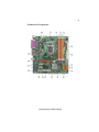
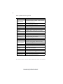
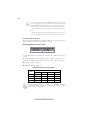
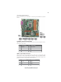
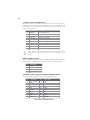
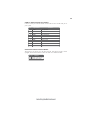
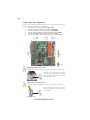
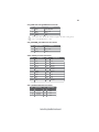
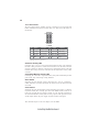
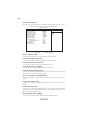
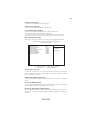
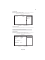
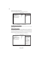
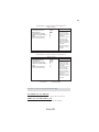
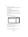
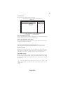
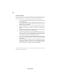
18
F_USB1~3: Front Panel USB headers
The motherboard has eight USB ports installed on the rear edge I/O port array.
Additionally, some computer cases have USB ports at the front of the case. If you
have this kind of case, use auxiliary USB connector to connect the front-mounted
ports to the motherboard.
Pin
Signal Name
Function
1
USBPWR
2
3
4
5
6
7
8
9
10
USBPWR
Front Panel USB Power
USB_FP_P0-
USB Port 0 Negative Signal
USB_FP_P1-
USB Port 1 Negative Signal
Front Panel USB Power
USB_FP_P0+
USB Port 0 Positive Signal
USB_FP_P1+
USB Port 1 Positive Signal
GND
GND
Ground
Ground
Key
No pin
USB_FP_OC0
USBOC-
Please make sure that the USB cable has the same pin assignment as
indicated above. A different pin assignment may cause damage or system
hang-up.
SPDIFO: SPDIF out header
This is an optional header that provides an SPDIFO (Sony/Philips Digital Interface)
output to digital multimedia device through optical fiber or coaxial connector.
Pin
1
2
3
4
Signal Name
+5V
NC
SPDIFOUT
GND
TCM/TPM: Trusted Cryptography Module/TPM Module Header
This header allows user to protect the PC from impermissible visit.
Pin
Signal Name
Pin
1
3
5
7
9
11
13
15
17
CK_P_33M_TPM
2
GND
FWH4
4
NC
PCIRST_L1
6
SMBDATA
PCIRST_L1
VCC3
GND
8
10
12
14
16
18
17
LPCPD_L
20
FWH0
NC
3VSBY
Signal Name
FWH2
FWH1
GND
NC
SIRQ
GND
SMBCLK
Installing the Motherboard