1
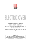
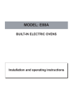
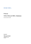
Serial Number
USE AND INSTRUCTION MANUAL
MOD. KF 1010 EV UD
rev. 1
TECNOEKA S.r.l.
Via I. Nievo, n.12/B - 35012 Camposampiero (Padova) Italy
Tel. +39.049.9300344 – +39.049.5791479 Fax +39.049.5794387
www.tecnoeka.com E-mail: [email protected]
_ TECNOEKA Srl __________________________________________________________ use and instruction manual _
Prodotti mirati per Ristorazioni, Pasticcerie,
Panetterie e Gastronomie
TECNOEKA Srl
Via I. Nievo, 12/B
35012 Camposampiero (PD)
Tel. +39 049 5791479 - +39 049 9300344
Fax + 39 049 5794387
www.tecnoeka.com – [email protected]
CE DECLARATION OF CONFORMITY
Annexed
Annexed document
document II A, of directive 2006/
2006/42/
42/CE
Manufacturer
Address
TECNOEKA Srl
Via I. Nievo, 12/B - 35012 Camposampiero (Pd)
Type of product
Electronic oven
Model
KF 1010 EV UD
TECNOEKA Srl declares that the above mentioned products conform to the safety
regulations under:
CEI EN 60335-1
- Low voltage directive 2006/95/EC
CEI EN 60335-2-42
- Electromagnetic compatibility Directive 2004/108/EC
CEI EN 55014-1
CEI EN 55014-2
CEI EN 61000-3-2
CEI EN 61000-3-3
CEI EN 61000-4-2
CEI EN 61000-4-4
CEI EN 61000-4-5
CEI EN 61000-4-6
CEI EN 61000-4-11
- Machine Directive 2006/42/CE;
- Directive on the general safety of products 2001/95/EC;
- Directive on the restriction in the use of dangerous substances in electrical
and electronic appliances 2002/95/EC;
- Directive on waste from electrical and electronic appliances 2002/96/EC.
Camposampiero, 17/01/2011.
_________________________________
Signature of a Representative of the Board of
directors
X:\Sgq\PRODOTTI\Fam. 1 - FORNI\FORNO ELETTRICO\LEka\MANUALI D'USO - Forno Elettrico
40 60 90 - LEka\Instruction manual KF 1010 EV UD - GB - agg - rev. 1.doc
_ page 2 _________________________________________________________________________________________
_ Electronic Ovens _ rev. 1 _____________________________________________________________ KF 1010 EV UD
Inde
Index
1
General information
1.1
1.2
2
Instructions for the installer
2.1
2.2
2.3
2.4
2.5
2.6
2.7
2.8
2.9
2.10
2.11
2.12
2.13
3
Technical specifications
Technical rating plate
Storage
Transporting the oven
Unpacking the oven
Removing the protective film
Disposing of the packaging
Positioning
Electric connection
Connection of power cable
Connection to water mains
Water outlet
Thermal breaker safety devices
Electronic circuit protection
Disposing of the oven
User instructions
3.1
3.1.1
3.2
3.2.1
3.2.2
3.2.3
3.2.4
3.2.5
3.2.6
3.2.7
3.2.8
General information
Residual risks
Operating instructions
Control panel
Programming cooking time
Programming cooking temperature
Programming cooking climate
Selecting cooking stage
Selecting cooking temperature
Selecting cooking program number
Motors at ½ speed function
3.2.9
Stop motors function
3.2.10 Pre-heating function
3.2.11 “Humidification” function
3.2.11.1 “Humidification” function with cooking cycle deactivated
3.2.11.2 “Humidification” function with the cooking cycle activated
3.2.12 Storing programs
3.2.13 Start/stop push button
3.2.14 On/off push button
3.2.15 Light push button
3.2.16 Cool cooking chamber push button
3.2.17 Self clean push button
_________________________________________________________________________________________ page 3 _
_ TECNOEKA Srl __________________________________________________________ use and instruction manual _
3.2.18
3.2.19
3.2.20
3.2.21
3.3
3.4
3.5
3.5.1
3.5.2
3.5.3
3.6
3.6.1
3.6.2
3.7
3.7.1
3.7.2
3.8
3.9
4
Cooking with “∆T” (Delta-T) function
Operating methods
Manual cooking
Programmed cooking
Black-out
Communications with PC
Cleaning
4.1
4.2
4.3
4.4
4.5
4.6
4.7
4.8
4.9
5
Clock + 1 push button
Enter or change current time
Start clock push button
Programmed ignition
Magnetic door sensor
First ignition
Cooking techniques
Steam cooking
Convection cooking
Convection + steam cooking
Other cooking techniques
Core temperature cooking technique
General information
Ordinary cleaning of the boiler
Extraordinary cleaning of the boiler
Cleaning the cooking chamber
Cleaning the fans
Cleaning the door seal
Cleaning the door
Cleaning the external casing
Periods without use
Maintenance
Maintenance
5.1
5.2
5.3
5.4
5.5
5.6
General information
Changing the lighting lamp in the cooking chamber
Changing the door seal
Possible faults
Possible alarms
Wiring layout
6
Technical service
7
Informations to the consumers
8
The Warranty
_ page 4 _________________________________________________________________________________________
_ Electronic Ovens _ rev. 1 _____________________________________________________________ KF 1010 EV UD
1. General information
This information has been prepared for your safety and that of others and we strongly advise
reading it carefully before installing and using the oven.
This instruction handbook must be kept together with the oven for future use. If the
handbook is mislaid please ask for a copy directly from the manufacturer.
1. If, on receipt of the goods, the packaging is damaged, write the following on the
delivery note: “I REVERSE THE RIGHT TO CONTROL THE GOODS”,
GOODS” specify the damage
and get the driver to sign in acceptance; send a claim in writing to the seller within 4
calendar days from the date of receipt. No claim shall be accepted after such period.
2. The oven has been exclusively designed for cooking and heating foodstuffs, any other
use is improper.
3. This oven has been designed for professional use and must only be used by qualified
trained persons. The oven must never be left unattended when it is operating.
4. In the case of faults or poor operations, turn the oven off, close the water supply valve,
unplug from the power mains and contact the authorized Service Centre.
5. All the installation and start-up operations must only be carried out by a technically
qualified installer, conforming to the manufacturer’s instructions in the full respect of
national standards in force.
6. For the periodic maintenance and repair work, contact your nearest Service Centre and
ensure only original spare parts are used. Failure to observe this instruction automatically
involves losing all rights to the guarantee.
N.B.: Improper
Improper and incorrect use and failure to observe the installation instructions releases the
manufacturer from any type of liability. In this sense, the instructions given in the paragraph
“POSITIONING” (paragraph 2.6) must be strictly followed.
1.1 Technical specifications
Overall measurements:
Height (with feet)
Width
Depth
Weight:
Weight:
Electric capacity:
3 convection heating elements
1 boiler heating elements
Max. electric capacity:
Appliance
I
Appliance class:
Water pressure:
kPa
150 – 250
Power supply voltage:
(50/60 Hz) 380/400V∼
380/400V∼ 3N
Power cable diameter:
5 x 6 mm2
Power cable type:
H07RNtype:
H07RN-F
Electric cable connection
Type Y
The noise level of the appliance when
when operating is less than 70 dB (A).
(A).
cm
cm
cm
Kg
kW
kW
kW
125
97
85
165
15
7,5
23,5
_________________________________________________________________________________________ page 5 _
_ TECNOEKA Srl __________________________________________________________ use and instruction manual _
1.2 Technical rating plate
Tecnoeka S.r.l., Via I. Nievo, 12/B
35012 Camposampiero (Padova)
ITALY
Model:
KF 1010 EV UD
Voltage:
380/400V∼ 3N 50/60Hz
Oven capacity:
Max. capacity:
Water pressure:
kW 15
kW 23,5
kPa 200
CERTIFICATION
520310727
SERIAL NO.
Made in Italy
The Technical rating plate is fitted on the rear panel of the oven.
2. Instructions for the installer
The following instructions are addressed to the qualified installer to enable him to perform
the correct installation, electric and water connection operations in conformity with current
safety legislation in force in the place where the appliance is installed.
The manufacturer will not respond for damage to people, animals and property due to
installation errors. Likewise the manufacturer is not responsible for breakage caused to the
appliance by incorrect installation.
2.1 Storage
If the appliance has been stored in a warehouse at a temperature below 0°C (min. allowed is
–10°C), it should be brought to a temperature of at least +10°C before it is turned on.
2.2 Transporting the oven
During transport, the appliance must be left in its original wooden cage to protect it against
damage.
2.3 Unpacking the oven
Remove all the packaging before installation, which is formed of a wooden cage that holds
the appliance and cardboard casing to protect it. Check that the appliance has not been
damaged during transport and if any damage is discovered immediately inform your retailer
and/or the haulier.
2.4 Removing the protective film
Before using the appliance, carefully remove the special protective film over the stainless steel
parts, without leaving any glue residue on the surfaces. If necessary, remove the residue at once
with a suitable non-inflammable solvent (e.g. acetone).
2.5 Disposing of the packaging
The packaging must be disposed of in accordance with current legislation in force in the
place where the appliance is installed. The various types of materials (wood – paper – cardboard
– nylon – metal staples) used for the packaging must be separated and delivered to the specific
waste disposal centres. In all circumstances the environmental protection regulations must be
strictly adhered to.
_ page 6 _________________________________________________________________________________________
_ Electronic Ovens _ rev. 1 _____________________________________________________________ KF 1010 EV UD
2.6 Positioning
Positioning - Check the place where the appliance will be installed to ensure that the
passages (doors and corridors) are wide enough (the appliance measurements are given in
Fig.1). The appliance must be positioned in a perfectly horizontal manner on a table (preferably
under a suction hood) or other similar surface, never on the floor
For easier access and to allow the air to circulate freely around the appliance, leave at least
50 cm between the left side and the wall (or other appliances), and at least 10 cm between the
back and the wall and the right side and the wall (see Fig. 1). The natural ventilation that is
needed to ensure efficient working for the oven is through the openings on the walls of the
outer covering (left side and back). Consequently, it is strictly forbidden to obstruct these
aeration openings, even partially and even for short periods. Failure to observe this specific
prohibition, shall release the manufacturer from all liability for the appliance and shall
immediately cancel any guarantee rights for the said appliance, because its constructive
conformity has been voluntarily compromised.
If the appliance is installed near walls, tops, shelves or other similar items, they must not be
inflammable or sensitive to heat, otherwise they must be protected by a suitable fireproof
covering.
In all cases, all fire prevention standards must be strictly adhered to.
This appliance cannot be built in nor positioned in series with others.
2.7 Electric connection
The connection to the main supply must be in conformity with current legislation in force.
Before making the electrical connections, make sure that:
- the voltage and frequency values of the power supply system match the values on the
"technical data" plate affixed on the rear of appliance;
- the pressure relief valve and the system must be able to support the appliance load (see
the data on the technical rating plate;
- the power supply system must be equipped with an efficient earth connection according
to current regulations;
- with direct-to-mains connection, a multi-pole switch must be installed between the
appliance and the mains with minimum between-contacts aperture of the overvoltage
category III (4000 V), sized for the load and conforming to current regulations (e.g. an
automatic magnetothermal switch);
- the multi-pole switch that is used for the connection must be easily accessible once the
appliance is installed;
- the yellow/green earth wire must not be disconnected by the switch
switch;
- the supply voltage must not differ from the rated voltage level by ±10% when the
appliance is operating;
- make sure that after inserting the power supply cord into the terminal block it does not
come into contact with any of the cooking range's hot parts.
- if the supply cable is damaged then it must be replaced by the manufacturer or by your
technical support or by a qualified person to avoid any risk.
_________________________________________________________________________________________ page 7 _
_ TECNOEKA Srl __________________________________________________________ use and instruction manual _
Installation / connection layout
Fig. 1 (Dimensions
(Dimensions in mm.)
_ page 8 _________________________________________________________________________________________
_ Electronic Ovens _ rev. 1 _____________________________________________________________ KF 1010 EV UD
2.8 Connection of power cable
To reach the power terminal board remove the left side of the appliance. Loosen the cableclamp on the back (at the bottom) of the appliance (see Fig. 1) and pass the cable through up
to near to the terminal board. Locate the leads against the terminal board so that the earth lead
is the last to detach from its terminal in the event of reverse pulling.
Connect the 3 phase leads to the terminals marked “1”
“1” “2” and “3”, the neutral lead to the
terminal marked “4” or “5” and the earth lead to the terminal marked
as shown in the
following layout:
380/400V~3N
1
2
3
4
5
(this electrical connection layout is also available near the power supply terminal board). Tighten
the cable clamp on the back (at the bottom) of the appliance and replace the left side. The
cable must correspond to those given in the “Technical specifications” table (paragraph 1.1).
The appliance must be connected to an equipotential system after checking its efficiency
according to current regulations.
This connection must be made between different appliances using the special terminal
marked with . The equipotential lead must have a minimum diameter of 2,5 mm2. The
equipotential terminal is on the rear of the appliance.
2.9 Connection to water mains
The oven must be supplied with softened drinking water with a hardness value of 0.5 to 5°F
(It is obligatory to use water softener to reduce the formation of scaling inside the boiler). The
water pressure must be in the range of 150 to 250 kPa (1.5 – 2.5 bar). If the water pressure
exceeds 2.5 bar, install a pressure reducer device upstream. If the pressure is below 1.5 bar, use
a pressure pump to increase the level.
The connection to the water supply is done using the ¾” threaded solenoid valve on the
back (at the bottom) of the appliance (see fig. 1), fitting a mechanical filter with a cut-off cock
(before connecting the filter, allow a certain amount of water to flow out in order to remove
any waste from the pipe).
N.B.: The water supply system must never be emptied when the boiler is operating. If necessary
turn the appliance off and let it cool before emptying the water supply system.
_________________________________________________________________________________________ page 9 _
_ TECNOEKA Srl __________________________________________________________ use and instruction manual _
min. 30cm
2.10 Water outlet
There is a drainage pipe on the back of the appliance (see Fig. 1) for emptying the cooking
chamber. A pipe of at least 30 mm internal diameter (DN30) must be connected to this pipe
that is resistant to the steam temperature. To avoid throttling, we advise using a rigid pipe
without any elbow bends along its length. The pipe must have a constant inclination of at least
5% along its length (the length is that from the outlet pipe from the appliance to the drain and
must not exceed 1 meter overall). The outlet pipe must flow into an open drain on the floor
(Fig. 2). If not, there must be a difference in height between the outlet pipe on the appliance
and the drain of at least 30 cm (see Fig. 3) to ensure the water flows out correctly. In conformity
with hygiene regulations in force, the pipe connected to the water outlet pipe on the appliance
must not be directly in contact with the outlet point.
max. 1mt
max. 1mt
Fig. 2
Fig. 3
2.11 Thermal breaker safety devices
The appliance is supplied with a manually resetting thermal breaker to protect against
excessive, dangerous temperatures which could be accidentally generated inside. If it is tripped,
the device cuts off the power supply to the appliance.
The boiler fitted on the appliance has an automatically resetting safety thermal breaker to
protect the heating element in the boiler from dangerous overheating, to guarantee constant
working.
2.12 Electronic circuit protection
The electronic circuit inside the electric components compartment is protected by fuses.
2.13 Disposing of the oven
The appliance is made using recyclable raw materials and contains no toxic or harmful
substances for people or the environment. The appliance, and its packaging, must be disposed
of in conformity with the current regulations in force in the place of installation. The various
materials used for its construction must be separated and delivered to the specialised waste
disposal centres. In all cases the environment protection regulations must be strictly adhered to.
_ page 10 _________________________________________________________________________________________
_ Electronic Ovens _ rev. 1 _____________________________________________________________ KF 1010 EV UD
3. User instructions
3.1 General informat
information
nformation
- When using the oven for the first time, we advise you to run it load-free at maximum
temperature for about one hour. In this way, any unpleasant smells, due to thermal
insulation, and grease residue from assembly are eliminated.
- This appliance must be exclusively used for the purposes for which it was expressly
designed, i.e. cooking foods in the oven, any other use is improper.
- The oven can be used for all oven cooking of pastry, bakery and gastronomy products,
fresh and frozen, for re-conditioning refrigerated and deep frozen foods, for steam
cooking meat, fish and vegetables.
- When placing food in the cooking chamber, allow a space of at least 40 mm between
pans to avoid over-obstructing the airflow.
- Do not use pans with edges higher than necessary: the edges act like barriers preventing
circulation of hot air.
- Pre-heat the oven before each time it is used to guarantee the best performance.
- For the cooking to be as even as possible, place the food evenly in each pan, considering
the size of the pieces, layers or the thickness.
- Do not salt the food when it is in the cooking chamber.
- To check the cooking cycle is proceeding correctly use the internal light in the chamber
do not open the door if it is not necessary, to avoid wasting energy and prolonging
cooking times.
3.1.1 Residual risks
- After a cooking operation, open the door cautiously, to avoid a violent outflow of heat
which could cause burns.
- While the oven is in operation, pay attention to the hot zones (marked on the appliance)
of its external surfaces.
- Place the machine on a bench or similar support, at a height of at least 60 cm from the
floor.
- The bench or support must be able to support the weight of the machine and house it
correctly.
- To prevent incorrect connection of the appliance, the relevant electrical and water
connections are marked by identification plates.
- The appliance contains electrical parts and must never be washed with a jet of water or
steam.
- The appliance is electrically connected: before attempting any cleaning operation, cut
power to the appliance.
_________________________________________________________________________________________ page 11 _
_ TECNOEKA Srl __________________________________________________________ use and instruction manual _
3.2 Operating instructions
3.2.1 Control panel
1. Time display
2. “+1” push button and hour/minute
display (on the time display)
3. Current time display push button (on
the time display)
4. Green signal light for an active stage
5. Phase selection push button
6. Time setting knob (“1”)
7. Temperature display
2
1
3
8. Set temperature in cooking chamber
9. Actual temperature in cooking
chamber
4
10. Set temperature for core probe
6
11. Actual temperature at core probe
5
12. Set “∆T” temperature
8
7
9
10
11
12
13. Temperature selection push button
(on temperature display)
14. Temperature setting knob (”2”)
15. Climate display led bar
(blue led = steam / red led = dry)
16. Motors at 1/2 speed push button
14
13
17. Stop motors push button
18. Pre-heating function push button
15
19. Climate setting knob (“3”)
16
20. Start/stop push button for cooking
cycle
21. Display programs
17
19
22. Storing programs push button
23. View programs push button (1÷99)
18
25. Cooking chamber light push button
21
23
26
27
24. On/off push button
20
26. Wash boiler push button
22
27. Cooking chamber cooling push
button
24
25
_ page 12 _________________________________________________________________________________________
_ Electronic Ovens _ rev. 1 _____________________________________________________________ KF 1010 EV UD
3.2.2 Programming cooking time
To set the cooking time (from 1 minute to 4 hours) use the knob no. “1”. The set values can
be seen on the time display.
3.2.3 Programming cooking temperature
temperature
To set the cooking temperature (between 50°C and 270 °C in the cooking chamber and
between 0°C and 100°C for the “∆T” and the core probe) use the knob no. “2”. The set values
can be seen on the temperature display.
3.2.4 Programming cooking climate
climate
To set the cooking climate (dry or steam) use knob no. “3”. The set value in percentage is
shown on the led bar formed of: 5 blue leds (from 20% to 100%) for the steam selection (turn
the knob in an anti-clockwise direction) and 5 red leds (from 20% to 100%) for the dry
selection (turn the knob in a clockwise direction). The white led shows when the climate
function is not activated.
3.2.5 Selecting cooking stage
. When the green led lights
To select the cooking stage (from 1 to 4) press the push button
up it shows the stage has been selected. The required cooking parameters (time/temperature/
climate) can be set for each selected stage. The push button can be pressed at any time to
check the time for each cooking stage.
When the oven is operating, the remaining cooking time can be seen for all 4 stages on the
time display (the flashing led shows which cooking phase is actually in progress).
An “infinite” time can be set in the 1st and 4th stages (turn the knob no. “1” in an anticlockwise direction): the time display shows the wording “inF
inF ” (1st stage) or “HoLd
HoLd”
HoLd (4th stage –
which is useful for keeping the food hot when it is cooked). The other stages cannot be selected
in these cases.
3.2.6 Selecting cooking temperature
To select the cooking temperature (in the cooking chamber / core probe ”∆T”) press the
push button
. When the green led lights up it shows the selected temperature, which can be
seen on the temperature display.
display
Temperature in the cooking chamber:
chamber When the oven is turned on the temperature in the
cooking chamber is automatically selected (led alight on
) . To set the required level turn knob
no. “2”. When the oven is operating, the set temperature (led alight on ) and the current
temperature in the cooking chamber (led alight on ) are alternatively displayed.
Core temperature in the food:
food: To set the temperature for cooking inside the food, press the
push button
until the led next to the
symbol lights up and then turn knob no. “2”.
When the oven is working (with the needle probe inside the food) the set temperature (led
) and the current temperature inside the food (led alight on ) are alternatively
alight on
shown.
∆T temperature (DELTA(DELTA-T):
T) To set the temperature for the “∆T” function, press the push
button
until the led lights up next to the ∆T symbol and then turn knob no. “2”. When the
oven is working (with the needle probe inside the food) the current temperature in the cooking
chamber (led alight on ) and the set temperature for “∆T” (led alight on ∆T) are alternatively
shown.
N.B.: If the cooking chamber temperature and the core temperature for the food are set, the “∆T”
temperature function is automatically deactivated.
If the core temperature for the food is set and then the “∆T” temperature, the cooking chamber
temperature function is automatically deactivated.
_________________________________________________________________________________________ page 13 _
_ TECNOEKA Srl __________________________________________________________ use and instruction manual _
3.2.7 Selecting cooking program number
To select the cooking program number (there are 99 programs in all) press the push button
(from 1 to 99) or the push button
(from 99 to 1). The selected program number is
shown on display programs. To rapidly view the programs keep the push button pressed.
3.2.8 Motors at ½ speed function
To activate this function press the push button
. When the green led lights up it confirms
the activation. This function remains operative until the push button is pressed a second time. If
this function is included in one of the four cooking stages, the passage to the next cooking
stage is automatically deactivated. This function cannot be activated during a programmed
cooking cycle.
cycle. By halving the speed of the motors (fans), the heating capacity is halved too and
therefore the cooking times and the amount to be cooked must be adjusted. (The different
noise of the motors is quite normal at reduced speed).
3.2.9 Stop motors function
function
. When the green led lights up it confirms
To activate this function press the push button
the activation. This function remains operative until the push button is pressed a second time.
If this function is included in one of the cooking stages, the passage to the next cooking
stage is automatically deactivated. This function can be activated and deactivated at any time,
even during a programmed cooking cycle.
When the motors (fans) are stopped, the heating elements and climate regulation are
deactivated, therefore if this function is included in a program, it can be used to delay the start
of the cooking cycle or as a pause during the cycle (for leavening the product inside the cooking
chamber).
3.2.10 PrePre-heating function
To activate this function press the push button
. When the green led lights up it confirms
the activation. The function is automatically deactivated when the pre
pre--heating temperature is
reached, otherwise, it can be deactivated by pressing the push button during a cooking stage
(the oven pre-heating can be cut off at any time).
If this function is activated in a programmed cooking cycle, it is not stored with the other
parameters of the program and, therefore, it must be activated each time a new cooking cycle
is started: either programmed or manual. The function adds a temperature delta ∆ only to the
temperature that was set in the first stage of the cooking cycle, to compensate any heat loss
caused by opening the oven door to introduce the food.
If this stage is activated, when the cooking cycle starts the time display shows the wording
“HEAt”. As soon as the pre-heating temperature is reached a beeper sounds, which stops only
when the oven door is opened for introducing the food (the wording “HEAt” continues
flashing). When the door is closed, the programmed cooking cycle starts automatically and the
time display shows the set cooking time.
_ page 14 _________________________________________________________________________________________
_ Electronic Ovens _ rev. 1 _____________________________________________________________ KF 1010 EV UD
3.2.11 “Humidification” function
AVAILABLE
CYCLES
THE HUMIDIFICATION FFUNCTION
UNCTION IS ONLY AVAI
LABLE FOR COOKING CY
CLES WITH DRY OR
NEUTRAL CLIMATE ((RED LED OR WHITE LED ALIGHT ON THE CLIMATE LIGHTED BAR).
).
ACTIVATED
GENERATOR
IT CANNOT BE ACTIVAT
ED WHEN THE STEAM GE
NERATOR IS WORKING (BLUE LED ON = STEAM
CLIMATE).
3.2.11.1 “Humidification” function with cooking cycle deactivated
key and keep it pressed until the
To activate the “humidification” function press the
second “beep” (the green led on the key goes off) and turn the knob “3” in an anticlockwise
direction (position 19 on the control panel), choosing the number of blue leds alight and,
therefore, the amount of humidity (the
the more blue leds there are alight the higher amount of
humidity).
This operation can be carried out for each single phase of the cooking cycle or for each phase
of the cycle.
The “humidification” function can be managed in “manual” cooking mode or it can be
stored in the cycle phases with the other parameters (time / temperature / neutral or dry cycle)
in “programmed” cooking mode.
Until the cooking cycle starts, the amount of preset humidity can be checked for each phase
of the cycle. Just keep the
key pressed until the second “beep” and the number of blue leds
key
alight is shown on the climate lighted bar (position 15 on the control panel. Keep the
pressed and turn the knob “3”, to change the number of lighted blue leds and the amount of
preset humidity.
When the cooking cycle starts, the green led on the
key flashes, confirming the
“humidification” function is active.
During the cooking cycle in “manual” mode, the “humidification” function can be
deactivated at any time and in any cycle phase by pressing the
stops flashing and goes off).
key (the green led on the key
3.2.11.2 “Humidification” function with the cooking cycle activated
To activate the “humidification” function, press the
key (the beep sounds) and keep it
pressed, turn the knob “3” in an anticlockwise direction (position 19 on the control panel),
choosing the number of blue leds alight and the amount of humidity (the
the more blue leds there
are alight the higher amount of humidity).
Release the
key and the green led begins flashing confirming that the “humidification”
function is active.
By acting in the same way, the amount of preset humidity is changed.
During a multi-phase cooking cycle, the “humidification” function remains active for the
entire phase that it has been set for, after which humidification is automatically deactivated.
With the cooking cycle active, the amount of preset humidity can be altered only in “manual
cooking” mode.
In “programmed cooking” mode the stored parameters, and therefore humidification,
cannot be altered until the cycle ends. Consequently the “humidification” function cannot be
deactivated either.
_________________________________________________________________________________________ page 15 _
_ TECNOEKA Srl __________________________________________________________ use and instruction manual _
3.2.1
3.2.12
2.12 Storing programs
Select the program number you wish to store. Set the parameter sequence: time/temperature
until the beeper
and climate for each of the four cooking stages. Press the push button
informs you it has been stored. To cancel a stored program, just replace it with a new one with
the same number, containing the new parameters for the four cooking stages. The new
program must then be stored.
3.2.1
3.2.13
.13 Start/stop push button
Once a programmed cooking cycle has been selected or a manual cycle set, press the push
button
to start cooking. The green led lights up and the beeper sounds to confirm the
cooking cycle has started. To interrupt the cycle the push button can be pressed at any time.
3.2.14 On/off push button
Press the push button
to turn the oven on and off. When the oven is off, the green led is
on and vice versa. When the oven is cooking, this push button is disconnected: to turn the oven
off you must first stop the cooking (pressing the START/STOP push button).
3.2.15 Light push button
Press the push button
to light the cooking chamber. When the green led lights up it
confirms the light is on. The light turns off automatically after 60 seconds. If the push button is
kept pressed until the beeper sounds it confirms that the light will remain on. To turn the light
off press the push button again.
3.2.16 Cool cooking chamber push button
To rapidly cool the cooking chamber at the end of a cooking cycle, hold the door open and
press the push button
. When the green led lights up it confirms the function is activated.
During forced ventilation, the temperature in the cooking chamber is shown moment by
moment on the temperature display.
3.2.17
3.2.17 Self clean push button
To begin washing the boiler, with the oven turned off (the OFF green led is alight), press the
push button
until the beeper sounds to confirm. When the green led is alight it confirms the
function is activated.
3.2.18 Clock + 1 push button
At the end of the cooking cycle the beeper sounds for 10 seconds and the figure “0000”
begins flashing on the display. While the figure is flashing, which lasts for 60 seconds, by
pressing the push button
the cooking time can be extended: each time the push button is
pressed the time is increased by one minute (the option is deactivated at the end of the cooking
cycle with the probe in the core). When the oven is turned OFF the time display shows the
current time: to change or enter the time (if it is missing) press the push button.
3.2.19 Enter or change current time
With the oven turned OFF, press the push button
and the two figures relative to the hour
begin flashing on the time display. Use the knob “1” to enter the current hour. The day of the
week is shown on the temperature display (1= 7 through to 7 = Sunday). Use knob no. “2” to
enter the current day. Press the push button
again and the two figures will start flashing on
the time display relative to the minutes. Use knob “1” to enter the current minutes. When the
push button
is pressed again the time display shows the complete time.
_ page 16 _________________________________________________________________________________________
_ Electronic Ovens _ rev. 1 _____________________________________________________________ KF 1010 EV UD
3.2.20 Start clock push button
With the oven turned ON or during the cooking cycle, when the push button
is pressed at
any time, the current time can be checked on the time display (the other displays are
deactivated).
3.2.21 Programmed ignition
With the oven turned OFF, when the push button
is pressed, the parameters are shown that
have been entered for programmed ignition: the time (time display), the day (temperature
display) and the cooking program number (program display). To change the parameters press
the push button . The two figures showing the hour begin flashing on the time display: use
the knob no. “1” to enter the required ignition hour. The figures showing the day start flashing
on the temperature display: use knob no. “2” to enter the required day (from 1 = Monday to 7
= Sunday). The two figures relative to the cooking program start flashing on the program
display: use the scroll buttons to enter the required cooking program number. Press the push
button
again and the two figures showing the minutes start flashing on the time display: use
the knob no. “1” to enter the required minutes. Press the push button
and the current time
is shown on the time display. Press
and the green led starts flashing to confirm that the oven
is on stand-by ready for programmed ignition.
To cancel programmed ignition press the push button
again.
3.3 Magnetic door sensor
This device stops the oven and the cooking cycle each time the door is opened.
3.4 First ignition
The oven can be used for the first time only after the chamber has been carefully cleaned
with a special detergent for stainless steel. The detergent must not contain acid substances
(chloride acid, bleach, etc.) or be abrasive. Alternatively the chamber can be washed with warm
soapy water or warm water and a drop of vinegar. Rinse well and dry with a soft cloth.
First ignition (without food inside the oven) serves to eliminate any unpleasant smells (which
are quite normal) due to the thermal insulation heating up that covers the cooking chamber and
any oil residues from assembly of the metal parts.
After turning the power on (close the unipolar switch fitted upstream from the appliance)
and the water (open the cut-off cock), proceed as follows (see the figure of the control panel):
- press the on/off push button;
- set the time (knob “1”) at one hour (shown on the time display);
- set a temperature (knob “2”) of 270°C for the cooking chamber (shown on the
temperature display);
- check the door is closed;
- press the start/stop push button: the cooking chamber starts heating up.
When the time is up, the oven turns off automatically and the beeper sounds for 10 seconds.
3.5 Cooking techniques
There are three different cooking techniques with this oven which can be used singularly,
one after the other or combined.
_________________________________________________________________________________________ page 17 _
_ TECNOEKA Srl __________________________________________________________ use and instruction manual _
3.5.1 Steam cooking (moist heat)
The boiler produces live hygienic steam which enters the cooking chamber without being
pressurised, where the fans make it circulate very fast.
The climate regulation system which allows dividing the steam production, in percentage,
should be set at 100%, while the cooking chamber temperature can be set between 50°C and
130°C.
Steam cooking is indicated where a boiled effect is required, and it has the advantage of
leaving the nutritional content of the food unaltered (the vitamins and flavour of the food are
conserved), the outer appearance (the colour is conserved, no lumps or air bubbles are formed
and the surface does not break up) and the weight is conserved, as no liquids are lost from the
food during cooking.
3.5.2 Convection cooking (dry heat)
The heating elements heat the dry air inside the cooking chamber. This heated air is evenly
distributed by the high speed of the fans. This gives an even temperature throughout the
cooking chamber and even cooking even when the oven is full.
This means that different types of food can be cooked on the various shelves (as long as they
need the same cooking temperature) without flavours and smells being mixed together.
The cooking chamber temperature can be set between 50°C and 270°C.
Besides evenly browning the food without having to turn it, convection cooking can be used
to cook au gratin and is particularly convenient for rapid defreezing, for sterilising preserves and
drying mushrooms and fruit.
3.5.3 Convection + steam cooking (dry heat + moist heat)
This type of cooking exploits the combination of dry and moist heat. The heat is dosed by the
climate regulation system which can divide, in percentage, the production of steam and the
production of dry heat (drying the cooking chamber), optimising the cooking climate for each
dish.
The cooking chamber temperature can be set between 50°C and 270°C.
The fact of using a hot-moist climate inside the cooking chamber with variable temperature and
moisture levels, is the most convenient and efficient way of cooking: cooking times are reduced,
the surface of the foods remains soft and does not form a crust, there is little weight loss and
the fatty mass is reduced.
The special hot-moist climate at low temperatures is ideal for re-conditioning food.
3.6 Other cooking techniques
3.6.1 Core temperature cooking technique
The temperature can be set inside the core of the food to be cooked, using the special
needle core probe that is supplied with the oven. The probe must be pushed into the centre of
the food in the thickest part, avoiding the bones. Place the food inside the cooking chamber
and pull out the thermal probe lead and close the oven door. The probe plug must be plugged
into the special socket (see Fig. 1) at the bottom of the control panel. Press the push button
to select the core cooking temperature (led alight on
) between 0°C and 100°C using knob
no. “2”, the temperature is shown on the temperature display.
When a cooking cycle is started with a core probe stage included (the time display shows the
wording “Prob”), when the set temperature is reached inside the food the cooking cycle passes
onto the next stage no matter what time has been set. If the core probe is activated within any
of the four stages, with the other three deactivated, the cooking cycle finishes automatically
when the set temperature inside the food is reached, no matter what time has been set.
_ page 18 _________________________________________________________________________________________
_ Electronic Ovens _ rev. 1 _____________________________________________________________ KF 1010 EV UD
Cooking with the core probe can be graduated over the four stages (for very delicate
cooking) and, for each stage, the temperature and the climate inside the cooking chamber can
be set besides the temperature inside the food.
As the thermal probe is a needle which can easily be removed or broken, we advise setting
the cooking time for the stage that it is used in.
If the probe is connected and operating, the stage finishes when the set temperature is
reached; otherwise, if the probe is not connected or is broken, the stage finishes at the set time.
If the probe is not connected or is broken, when the cooking cycle starts the beeper sounds
intermittently for 10 seconds, the time display shows the flashing message “Prob” and the
previously set temperature disappears from the temperature display ( - - - ).
The core temperature of the food can also be measured (when no temperature has been set):
it is sufficient to slide the needle probe into the food.
In this case, when the cooking cycle has been started, when the push button
is pressed
the temperature is selected automatically (shown on the temperature display) that is measured
by the probe (led alight next to ).
Warning: Before removing the food from the oven after cooking with the core needle probe.
Warning
Carefully remove the hot probe from the cooked food, taking care not to leave it
hanging out of the cooking chamber as it could cause burns.
We advise leaving it to cool down before using it again – to avoid damaging pricks in
the food.
To prevent any irreparable damage to the thermal piercing probe (core probe) do not
use it in high temperature cooking ABOVE 230°C, and ensure that the probe lead is
not touching any hot metal surfaces inside the oven.
3.6.2 Cooking with “∆T” (DELTA(DELTA-T) function
This function allows keeping the difference (∆T) between the temperature inside the food
(measured by the needle probe) and the temperature in the cooking chamber constant. This
means that the temperature in the cooking chamber is the sum of the temperature inside the
food and a fixed “∆T” temperature that is set by the user (see the graph).
Cooking temperature (°C)
200
150
Cooking chamber
temperature
100
50
Temperature
inside the food
Delta T temperature
∆
0
Cooking time (min.)
The Delta-T temperature is the difference between the
temperature inside the food and the temperature in the
cooking chamber
In practical terms, there is a gradual increase of the temperature in the cooking chamber,
with a constant difference with respect to the temperature inside the food which, thanks to this
constant difference, is cooked slowly and gently (in meat the proteins are protected, as no
surface tension is caused by the rapid formation of the crust).
After selecting the temperature inside the food (core temperature) and setting the level (knob
again to select the “∆T” function (the led next to the ∆T symbol
“2”) press the push button
lights up) and to set the temperature (knob “2”) (on the basis of our experience this
temperature should be between 30°C and 70°C).
When the “∆T” function is used for cooking, the method for using the needle probe is the
same as that described in paragraph 3.6.1.
_________________________________________________________________________________________ page 19 _
_ TECNOEKA Srl __________________________________________________________ use and instruction manual _
3.7 Operating methods
methods
3.7.1 Manual cooking
After turning the oven ON (green led off), set the various cooking parameters.
Set the cooking time (shown on the time display) using the knob no. “1”:
- “inF” (stages excluded /stage led off)
- from 1 minute to 4 hours per stage (“inF” excluded / stage leds alight)
Set the cooking temperature (shown on the temperature display) for one or more stages,
using knob no. “2”:
-
cooking chamber (from 50°C to 270°C / led alight on )
- core probe (from 0°C to 100°C / led alight on )
- ∆T / DELTA-T (from 0°C to 100°C/ led alight on ∆T)
Set the cooking climate (shown on the led bar) for one or more stages, using knob no. “3”:
- neutral (white led alight)
- only dry (all 5 red leds alight / 100%)
- only steam (all 5 blue leds alight /100%)
- variable dry (red leds 1 to 4 alight /from 20% to 80%)
- variable steam (blue leds 1 to 4 alight /from 20% to 80%)
Set the pre-heating function (optional) pressing the push button .
Set the motors at ½ speed function (optional) for one or more stages, pressing the push
button
.
Press the push button
to start the cooking cycle.
Remember:
Remember
1. If the cooking cycle is not controlled by the core probe and has been divided in one or
more timed stages, the oven turns off automatically when the set time for the single
stage or all the different stages together is over. If an “inF” (infinite) time has been set,
the oven continues until the operator turns it off manually pressing the push button .
2. If the cooking cycle is controlled by the core probe and has been divided in one or more
stages, timed if required, when the temperature set on the probe is reached it passes
onto the next stage; if it has been set for a single stage, timed if required, or for an “inF”
time, the cycle finishes and the oven turns off automatically, no matter what time was
set for the stage.
3.7.2 Programmed cooking
When the cooking programs have already been stored (a cooking cycle corresponds to each
program number for a specific type of food) it is very easy to use them.
Turn the oven ON (green light off) select the stored program number (shown on the program
or
.
display) using the push buttons
Press the push button
to start the cooking cycle.
At the end of the cooking cycle the oven turns of automatically and the beeper sounds for 10
seconds.
Remember
er: Before beginning the cooking cycle, the parameters can be checked that have
Rememb
er
been set for the four stages (pres the push button ) and they can be changed if
wished. For the changed parameters to become operative, they must be stored
(press the push button until the confirming beep is heard).
It is no longer possible to change the value of the memorized parameters once
the cooking cycle is started.
_ page 20 _________________________________________________________________________________________
_ Electronic Ovens _ rev. 1 _____________________________________________________________ KF 1010 EV UD
3.8 BlackBlack-out
When the power supply returns after a black-out, the oven will continue working counting
the remaining time for the cooking cycle after the interruption.
3.9 Communications with PC
At the bottom of the control panel (seen from below) there is an inlet (remove the rubber
protection) for a serial gate for interactive communications with a PC.
If this gate is connected to a PC with wineka software (optional), up to 99 preset cooking
programs can be transmitted to the oven memory for all the operating parameters; likewise, the
cooking programs that are already stored in the oven memory can be acquired by the PC.
4. Cleaning
4.1 General information
Before beginning any sort of cleaning work on the appliance, turn the power supply off (at
the magnetothermal safety switch) and the water supply (by closing the cut-off cock) and then
let the oven cool down completely.
The appliance must be cleaned frequently, preferably daily, to guarantee best operations and
long life. This is an electric appliance therefore for obvious reasons water should not be used in
excess for cleaning. However, it is absolutely
absolutely forbidden to wash the appliance with water jets,
especially if they are pointed towards the aeration vents on the metal surface of the outside
casing (this could cause dangerous infiltrations that would damage the electric parts).
If grease remover detergents are used to clean the stainless steel, ensure they do not contain
corrosive acids (no sort of chlorine, even if it is diluted) or abrasive products. Follow the
indications given on the product and the warnings about its use, wearing rubber gloves during
cleaning.
Do not use iron pads, steel wool or scrapers as they would ruin the surfaces.
Do not leave food on the steel surfaces for a long time that contain acid substances (lemon
juice, vinegar, salt, etc.) as they could cause corrosion.
4.2 Ordinary cleaning of the boiler
Each time the oven is turned on, the water in the boiler is emptied and a washing and rinsing
cycle beings. During this phase, the oven can be used normally, there could just be a slight delay
in producing the steam, should it be needed for the cooking stage. The water is emptied from
the boiler (at regular intervals) even when the oven is working.
4.3 Extraordinary cleaning (decalcification) for the boiler
The innovative design of the boiler (with the heating element on the outside and not
immersed in the water), the washing and rinsing cycle that is systematically repeated each time
the oven is turned on and the fact that softened water is used (hardness between 0.5°F and
5°F) all aid in drastically slowing down the formation of lime scale inside.
However, to get the best performance from the boiler, we recommend decalcification at least
every 6 months (for ease, this can be done at the end of the working day).
Proceed as follows (Fig. 4):
- Turn the oven OFF (green led alight) and let it cool down;
- unscrew the threaded plug “A” on the top of the oven, taking care the seal “B” does
not fall;
_________________________________________________________________________________________ page 21 _
_ TECNOEKA Srl __________________________________________________________ use and instruction manual _
A
B
Fig. 4
-
-
use a funnel to pour the descaling liquid into the hole (an amount of 2500 ml = 2.5 litres
is sufficient), avoiding pouring it over the steel surface (vinegar for food use is ideal – it
does not contain any corrosive substances for stainless steel, it is an effective limescale
remover and is compatible with food use);
screw the threaded plug firmly in place so that the seal guarantees it is perfectly
watertight;
leave the limescale remover liquid to work for at least 8-9 hours (or overnight);
-
press the push button
and keep it pressed until the confirmation beep is heard (the
green led lights up to confirm the function has been activated).
An automatic procedure will empty the limescale remover from the boiler and will begin a
washing cycle that lasts for about 5 minutes. The green led goes off on the push button when
the cycle is finished.
The oven is now ready for use.
Warning:
To avoid dangerous water leaks from the oven boiler, the threaded cap “A” must be
Warning
perfectly closed and sealed when the oven is working.
4.4 Cleaning the cooking chamber
For hygienic reasons, it is good practice to clean the cooking chamber at the end of each
cooking cycle, otherwise it should be cleaned at least once at the end of each day’s use.
For easier cleaning, remove the side grills by unscrewing the 4 fixing screws (hold the reeded
nut between your thumb and forefinger and turn it in an anti-clockwise direction) remove the
drainage plug on the bottom and proceed as follows:
- spray a special degreasing product for stainless steel on the external walls, on the fan
casing (do not spray it through the fan grids) and on the glass inside the door;
- leave the product to work for approximately 20 minutes with the door closed;
- turn the oven on to 70-80°C;
- run a cycle with maximum steam (100%) for around 15 minutes;
- when the cycle is complete turn the oven off, leave the cooking chamber to cool down
and rinse well;
- Dry with a soft cloth or run a heating cycle, with the temperature at 150-160°C for
about 10 minutes (the cycle can be repeated if necessary).
The side grills and drainage plug must be cleaned separately and then replaced.
When cleaning is terminated, leave the oven door slightly ajar.
4.5 Cleaning the fans
The fans must be periodically cleaned with specific anti-limescale products. All the parts must
be carefully cleaned, removing all limescale deposits.
To have access to the fans remove the fan casing after removing the screws that fix it to the
cooking chamber. When cleaning is complete, replace the casing and screws.
_ page 22 _________________________________________________________________________________________
_ Electronic Ovens _ rev. 1 _____________________________________________________________ KF 1010 EV UD
4.6 Cleaning the door seal
For hygiene and good operations, it is good practice to clean the door seal at the end of each
day’s work. It should be carefully washed with warm soapy water, rinsed and dried with a soft
cloth. Any incrustations or food deposits must be carefully removed, without using sharp metal
tools which could irreparably damage the seal.
4.7 Cleaning the door
The glass on the door inside the cooking chamber can be cleaned with the same degreaser as
used for cleaning the chamber or a normal glass cleaning product can be used (non toxic).
Normal glass cleaning products can also be used to clean the glass on the outside of the door,
or simply warm soapy water, rinse and then dry the glass well with a soft cloth.
If dull marks form between the two door glasses, these can be removed by dismantling the
internal glass.
To do this act on the appropriate hooks for closure of the glass.
After cleaning the glass close the external glass acting on reverse.
4.8 Cleaning the external casing
The external steel surfaces should be cleaned with a cloth soaked in warm soapy water or
with a drop of vinegar added, they should be rinsed well and dried with a soft cloth.
If you use specific cleaning products, they must correspond to the requirements for cleaning
given in the paragraph “General information” (paragraph 4.1).
You should also remember that the table the appliance stands on or the surrounding floor
should not be cleaned using corrosive acid products (for example muriatic acid), as the fumes
that are given off could attack and damage the external steel casing.
4.9 Periods without use
If the appliance is not used for a long time, it is good practice to unplug it from the mains (at
the magnetothermal safety switch upstream from the appliance) and to turn off the water with
the cut-of cock on the main supply line. It should be carefully cleaned inside the cooking
chamber and outside, taking special care to remove any salt deposits which would cause
corrosion to the steel surfaces.
We also advise protecting the appliance with an oily base spray (e.g. Vaseline oil), which
forms an effective protective film on the surface of the steel.
A suitable covering would also protect the appliance from the dust.
5. Maintenance
Maintenance
5.1 General information
A periodic control (at least once a year) of the appliance aids to guarantee long life and
correct operations.
Any sort of maintenance work on the appliance must be done exclusively by technically
qualified operators who have been trained in the maintenance work on this appliance.
Before beginning any sort of maintenance work on the appliance, turn the power supply off
(at the magnetothermal safety switch upstream from the appliance) and let it cool down.
Access is gained to the inside components that could require maintenance work by removing
the left side of the appliance.
5.2 Changing the lighting lamp in the cooking chamber
chamber
The lamp is housed between the two door glasses; to replace it remove the external glass as
described in the paragraph: “Cleaning the door”.
Open the external glass, unscrew the 2 screws securing the lamp protection cover with the
appropriate tool and replace the lamp with another with the same specifications: 12V 35W
300°C (this is a halogen lamp and should not be touched with your bare hands)
_________________________________________________________________________________________ page 23 _
_ TECNOEKA Srl __________________________________________________________ use and instruction manual _
5.3 Changing the door seal
The door seal has a rigid profile with fixing tabs. The profile must be fitted into the guide on
the face of the cooking chamber.
To change the seal, remove the old one from the guide by pulling hard at the four corners.
Clean any dirt from the guide and introduce the new seal (to make this operation easier, we
advise dampening the seal profile with soapy water).
5.4 Possible faults
Type of fault
Control panel completely off
(the oven does not work)
Cooking cycle set and START
push button pressed: the
oven does not work
Cause
Corrective action
-
Incorrect electric connections to the mains
No mains voltage
Thermal break safety device tripped
Electronic card protection fuse (power)
burnt
- Door open or ajar
- Damaged magnetic sensor
- Seal not fitted correctly
Door closed: steam comes
out of the seal
- Damaged seal
-
- One of the motors is blocked or turns
slowly
Lighting lamp in the cooking
chamber does not work
not
- Damaged lamp feeder
powered
-
- The motors do not go into reverse
- Heating element
damaged
- Damaged lamp
-
- Handle prong loosened
The oven does not cook
evenly
-
or
is
-
Check the mains connection
Restore mains voltage
Reset the thermal break safety device
Contact a qualified technician to
repair the sensor
Close the door
Contact a qualified technician to
repair the sensor
Check the seal fitting
Contact a qualified technician to
repair the seal
Contact a qualified technician to
repair the prong
Contact a qualified technician to
repair the motor
Contact a qualified technician to
repair the motor
Contact a qualified technician to
repair the element
Change the lamp
Contact a qualified technician to
repair the feeder
_ page 24 _________________________________________________________________________________________
_ Electronic Ovens _ rev. 1 _____________________________________________________________ KF 1010 EV UD
5.5 Possible alarms
alarms
Type of alarm
The temperature display shows the
message “Er1”.
“Er1” Oven heating is
deactivated.
The temperature display shows the
message “Er2” and an alarm buzzer
sounds for 30”. Press the START/STOP key
to stop the alarm buzzer. The cycle only
continues if the cooking time has been set.
“Er3”is
“Er3” displayed on the temperature
display and an alarm is activated that can
button.
be silenced by pressing the
Cooking can continue but it is necessary to
remove the cause of the fault causing the
electronic board to overheat.
The temperature display shows the
message “Er7” (steam generator discharge
fault). Steam generator washing is
deactivated but the generator continues
working. Press the START / STOP key to
turn off the alarm.
The temperature display shows the
message “Er8”. The steam generator
heating function is deactivated. The other
generator functions remain active. Press the
START / STOP key to turn off the alarm.
The temperature display shows the
message “Er9”.
“Er9” The oven only continues
working in convection mode (dry heat),
Press the START / STOP key to turn off the
alarm .
Cause of the alarm
Corrective action
- Cooking cell sensor-electronic
board/microprocessor connection
interrupted.
- Check the electronic
board connection
- Cooking cell sensor damaged.
- Call a qualified
technician to repair it.
- Cooking cell sensor-electronic
board/microprocessor connection
interrupted.
- Check the electronic
board connection
- Core pin probe damaged
- Call a qualified
technician to repair it.
- Aeration openings present in the
metal walls blocked
- Unblock the openings
- Heat sources too near the oven
- Eliminate the heat
sources
- Steam generator discharge
solenoid valve damaged.
- Call a qualified
technician to repair it
- Steam generator discharge
solenoid valve obstructed by
limescale.
- Call a qualified
technician to repair it
- Preheating temperature sensor in
the steam generator damaged.
- Call a qualified
technician to repair it
- Heat generator thermal safety
device activated
- Call a qualified
technician to repair it
- Heat generator level sensor
covered with limescale.
- Call a qualified
technician to repair it
“Hot” flashes on the temperature display.
The oven stops automatically and the alarm
is activated for 30 seconds.
The oven can be restarted only when the
electronic board has completely cooled
down
- Overheating due to risk of faulty
electronic board /
microprocessor. Sources of heat
too close to the oven.
The time/temperature display shows the
message “no H2o” (no water in the steam
generator).
Steam generator heating is deactivated,
Press the START / STOP key to turn off the
alarm.
- Water line connections do not
conform
- Cut off valve closed
- Water intake filter obstructed
- Water intake solenoid valve
damaged
- Wait for the board
temperature to fall
within the working
limits. Remove all
sources of heat away
from the oven. The
oven restarts
automatically.
- Check the water line
connection
- Check the valve
- Clean the filter
- Call a qualified
technician to repair it
_________________________________________________________________________________________ page 25 _
_ TECNOEKA Srl __________________________________________________________ use and instruction manual _
5.6 Wiring layout
WIRING LAYOUT
M
MI
B1-B2-B3-B4
R1-R2-R3
L-L1
T
T1
T2
E1-E2-E3
E4
E5
E6
Power supply terminal board
Door microswitch
Contactor coil
Circular heating elements
Oven lighting lamp
230/12V transformer
Oven safety thermostat
Boiler safety thermostat
Water solenoid-valves
Boiler filling solenoid
Steam breather pipe solenoid
Boiler discharge solenoid
MOD. KF 1010 EV UD
Key
C1-C2-C3
V1-V2-V3
S1
S2
S3
S5
SMI
SD
SM
SB
BO
Capacitors
Radial motorised ventilators
Cooking chamber probe
Food core probe
Boiler pre-heating probe
Boiler level probe
Microprocessor card
Display card
Motorised card
Boiler level card
Boiler
_ page 26 _________________________________________________________________________________________
_ Electronic Ovens _ rev. 1 _____________________________________________________________ KF 1010 EV UD
6. Technical service
Before leaving the factory, the appliance was completely regulated and tested by expert
specialised personnel to guarantee the best operating results.
All repairs and settings must be performed with utmost care and attention, respecting
national safety regulations in force. Always contact your retailer or our nearest Service Centre,
giving details of the problem, the appliance model and the serial number (on the rating plate on
the rear panel).
For any maintenance the user can contact Tecnoeka by calling the telephone numbers on the
cover or going to www.tecnoeka.com.
www.tecnoeka.com
7. Informations
Informations to the consumers
Further to Directive 2002/96/EC, the symbol of the crossed rubbish skip on
the appliance means that at the end of its life, the product must be
disposed of separately from the other rubbish. The user must hand the
appliance to a specialised waste collection centre for electric and electronic
equipment.
The separate collection of the rubbish and subsequent treatment, recovery and disposal help to
produce other equipment using recycled materials, reducing the negative effects on the
environment and public health, which would be caused by incorrect management of the
rubbish.
Should the user dispose of the product abusively, administrative sanctions would be applied.
_________________________________________________________________________________________ page 27 _
_ TECNOEKA Srl __________________________________________________________ use and instruction manual _
8. The Warranty
Your appliance is covered by warranty. The seller will replace or repair (and his decision will be final),
free of charge for the customer, only those parts that are defective due to a manufacturing fault on
condition that, under penalty of forfeiture:
− for domestic equipment, the customer notifies the fault within two months from the date when
he/she discovered it and anyway within 2 years form the date of purchase;
− for professional equipment, the customer notifies the fault within 8 days from the date when
he/she discovered it and anyway within 12 months from the date of purchase,
by registered letter with acknowledgement of receipt and enclosing the invoice or receipt proving the
purchase.
Apart from the case when the customer cannot produce the invoice or receipt proving the purchase or
when the above-mentioned terms are not complied with, the warranty is expressly excluded in the
following cases:
1) faults or breakage caused by the transport;
2) wrong or incorrect installation of the product (for instance because of insufficient draught of the
flue or exhausts) in light of the instructions given in the user’s handbook supplied with the
product;
3) inadequate or abnormal electrical, hydraulic and/or gas supplies;
4) carelessness, negligence or incompetence in using the product in light of the instructions given in
the user’s handbook supplied with the product;
5) use of the product for uses different from the one for which it was built or anyway in a manner
not compliant with the instructions given in the user’s handbook supplied with the product;
6) tampering with the product;
7) adjustments and/or maintenance and/or repairs carried out by unauthorised personnel and/or
with non original spare parts;
8) inadequate or careless maintenance of the product in contrast with the user’s handbook supplied
with the product;
9) damages caused by fire, natural disasters and accident as well as by any cause not attributable to
TECNOEKA SRL.
The warranty explicitly excludes:
excludes varnished or enamelled parts, knobs, handles, movable or removable
plastic parts, bulbs, glass parts, refractories and any accessories.
TECNOEKA SRL cannot be held responsible for any damages, either direct or indirect, caused by the
product breaking down or following its non-use.
Any repairs carried out during the warranty do not cause said warranty to be extended or renewed.
Nobody is authorised to modify the terms and conditions of the warranty or to issue new verbal or
written warranties.
The warranty is valid only for appliances installed in the European Union.
Any dispute shall be settled by the competent Court in Padua.
Warning for the Buyer:
1. the cooking appliance is designed only for cooking purposes while the heating appliance is
designed only for heating domestic environments;
2. TECNOEKA S.r.l. does not install the appliances; the seller shall be responsible for any installation
carried out;
3. TECNOEKA S.r.l. cannot be held responsible for any damages, either direct or indirect, to people,
pets or property caused by the appliance breaking down or following its non-use.
The Manufacturer cannot be held responsible for any inaccuracies due to misprints or mistakes in
copying in this handbook. The Manufacturer reserves the right to modify the products as he deems
fit, also in the interest of the user, without affecting the vital characteristics of functionality and
safety.
_ page 28 _________________________________________________________________________________________