1
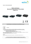
Jorgensen Laboratories, Inc. Premier Dental Scaler / Polisher User Manual Dental models not included J1180 Scaler Polisher / J1181 Scaler Jorgensen Laboratories, Inc. 1450 Van Buren Ave Loveland, Colorado 80538 Toll free 800-525-5614 Fax 970-663-5042 Jorvet.com Contents 1. Hazards, Warnings & Sterilization 2. Description and Functionalities of Components 3. Installation & Operation of Scaler and Micromotor 4. Codes for Accessories & Replacement Parts 5. Troubleshooting 6. Warranty Terms 7. Specifications ̱ʹ̱ 1. Hazards, Warnings & Sterilization This equipment only to be used by a qualified veterinarian or technician ¾No one with a pacemaker should operate this unit ¾A grounded AC power cord must be used with this equipment. The J1080/ J1081 should be powered from a separate wall outlet with a grounding point. If you plug into a GFI (ground fault interrupt) outlet it may trip the GFI socket due to the high sensitivity of the socket. ¾Place machine on level stable platform or surface ¾Do not place unit on or near any source of heat ¾Unit should be located where normal air flow will circulate freely around the case when in use this will avoid overheating. ¾Water input hose is subject to deterioration by aging, chemicals in the water supply, excessive flexing and pressure fluctuations. As an added precaution water supply should be turned off or pressure on tank relieved at the end of the day. Remember to turn water back on prior to use the next day ¾Do not remove external cover from the unit! There are no serviceable parts inside, allow only qualified technicians to service your scaler. ¾Handpiece quick connect is very strong but care should be taken not to pull with excessive force on cord. It is the responsibility of the dental professional using this device to be fully trained in the proper use of ultrasonic scalers. The operator must be observant of possible changes in performance during a procedure and immediately discontinue use of this product and determine the cause of such changes before continuing the dental. Performance varies slightly between manufacture or ultrasonic scalers, so the operator must become familiar with the operating parameters and adjustments of this particular device. Performance varies between ultrasonic inserts due to style, model and age of the insert. Sterilization ¾Manufacture recommends that all operators of this ultrasonic unit wear at least one pair of surgical rubber gloves and for extra prevention wear double pairs of gloves to isolate operator from infection or cross contamination of other patients. ¾It is recommended that eye and face protection be used during the use of this unit to prevent saliva spray from being inhaled and from entering the operators eyes. ¾Operator should be careful not to puncture the skin with any insert or tip containing saliva from patients. ̱͵̱ ¾Clean outer surface of unit with federally approved non-immersion water based cold sterilization solution, then dry immediately with clean air or paper towels. ¾Do not autoclave detachable handpiece assembly. This will void manufactures warranty. A federally approved water based cold sterilization solution (J833 Pink Germicide) may be used to wipe down detachable handpiece assembly however DO NOT get sterilization solutions on electrical contacts of the handpiece connector as this will cause oxidation and poor electrical connection. Dry all surfaces with clean air or paper towels. 2. Description and Function of Components A B C D E F A. Handpiece Receptacle – Accepts male side of handpiece connector B. Power Control – Adjusts the output of power to the insert tip. C. Polisher Speed control – Speed control for micromotor ** Found only in the J1080 combo units D. Water Control – Adjusts flow of water to handpiece and insert tip rotate higher water flow to the right, lower water flow to the left. E. On / Off Scaler / Motor Pack selector switch- located on right side of front panel, switch has three positions. Off when centered, ON when switch is moved up or down. When scaler switch is moved upward the scaler portion of the unit is activated. When switch is moved downward the motor pack is activated and ready for polishing. F. Indicator LED- Lights up when toggle switch is set to scaler /polisher ̱Ͷ̱ Handpiece Assembly The handpiece assembly is used to accept the interchangeable insert tips. It is connected to the autoscaler front panel via the handpiece receptacle. Be sure to plug and unplug scaler cord carefully, grasping plug itself and not the cable attachment. Open end of handpiece will Accept inserts J452D1 – Universal insert, J452D2 – Spatula Insert or the J452D1P – Periodontal Insert. ** Note – Inserts are extremely fragile, if one is dropped or bent it may not cavitate or function properly and may operate at a higher than normal temperature and should be replaced IMMEDIATELY. 3. Installation & Operation Guide Installing the Handpiece Assembly I. II. III. V. Align the electrical contacts of the male connector with the same on the female panel connector. Gently insert connector ( it should slide in with very little effort, if the connector does not align DO NOT FORCE IT. Turn connector body in either direction until connector correctly aligns and goes in easily). Once connector has been completely inserted, screw outside lock ring to the right (clockwise) with light finger pressure until it stops. Do not over tighten lock ring. *Be careful not to cross thread the lock ring To remove connector, unscrew lock ring to left (counter clockwise) and gently pull outward grasping the entire connector body. ̱ͷ̱ Installation & Operation of Autoscaler I. Upon receipt of your unit carefully unpack and make sure that The toggle switch is in the Off – O position. II. The water control knob should be in the high position. * Note – it is normal for the knob to turn past the high position several rotations which will increase water flow substantially. III. Set the power knob all the way to the left in the low position. IV. Plug the male water quick connect into the water source. IE : J452D4 – Portable water tank J452D19- Faucet Connector J452D14- Saddle valve with female quick connect for inline water supply. * Note: it is recommended that a line filtration device J452D13 be used to remove larger particles before entering the scaler. Plug Power cord into the wall, press toggle switch to the ON- I position. V. VI VII Hold the handpiece in a vertical (upright) position and step on the foot switch. Within 10-15 seconds water should come out of open end of the handpiece. If no water turn water control knob clockwise to get water flow and or check waterline connections. * Note- inserts and handpiece will burn out in 45-60 seconds in the absence of water. Never touch the vibrating end of the insert tip to any flesh such as cheek, tongue or gums as this will cause a friction burn to the patient. The tip should touch primarily the calculus on the tooth surface and NOT the enamel of the tooth. Important to always keep the insert in motion to avoid heat buildup on the tooth. Select insert. Moisten rubber O-Ring before inserting into handpiece.While holding the handpiece upright place insert into open end of the handpiece and with a gentle press and turn motion the insert should snap fully into place. Do Not Force Insert. ̱̱ Scaling handpiece O-ring – moisten with H2o when inserting Scaling insert VIII While holding handpiece upright, press foot switch and water should Begin to exit the insert. Allow the air to escape for about 10-20 seconds. Turn power to medium position and the insert should vibrate with a strong mist. Turn water knob to right if there is no mist or weak misting. The inserts may give a drip and mist combination this is normal and actually preferred by most periodontal professionals. IX. The application of the power knob is for controlling the output power to the insert tip. The operator can select the exact power needed for cleaning, set the power to low / medium for cooler handpiece / insert temperature. * Note - if your insert will not vibrate the problem could be with your insert. Before requesting service try another insert. The high power setting is for applications where excessive amount of calculus is built up. The power setting can be used for periodontal sub gingival curettage and root planning procedures. Most scaling should be done on the low to medium power settings. ** Note – DO NOT use excessive pressure with your scaler, use gentle rapid motion with small overlapping strokes, being certain that the scaler tip remains at a 15 degree angle to the tooth surface. ̱̱ Unit is now ready for use. Shut Down Procedure I. II. Turn water supply off either by releasing pressure from portable water tank ( J452D4 ) or by disconnecting quick water connector from water source. Remember to turn water back on with the next use. Press toggle switch to the off – O position. LED light should be off. Installation and operation of micromotor / polisher ***If you have a scaler only skip this part*** I. The power selector switch should be centered to the OFF position II. Place the plug from the micromotor handpiece into the socket located on the right rear side of the console. Slip a U-style snap on prophy angle J1180D3 onto the steel connector of the micromotor handpiece. This is done by aligning the slot on the prophy angle with the pin on the micromotor and applying downward pressure to the prophy angle thus sliding together. * applying straight pressure is all that is needed DO NOT TWIST while connecting. * If prophy will not fit ensure it is a U-style prophy angle. Only U-style prophy angles will work with this unit. Disposable prophy angles / E-style prophy angles will not work with this unit and may void warranty if used. ̱ͺ̱ Alignment Pin Slot on prophy angle III. Attach the snap-on polishing cup to the prophy angle head cap. Move the power selector switch downward to the “polisher” position the green indicator lamp should be illuminated. IV. Rotate the speed control knob to the left (LOW SPEED) until it stops. Now depress the foot pedal to become familiar with the way the micromotor handpiece operates. Slowly rotate the speed control knob from the left to the right to increase speed of the micromotor. This provides for a smooth progression of speeds from low of approx 450 RPM’s to the high which is approaching 12,000 RPM’s. Not only does this unit furnish a wide range of speeds but also delivers a high degree of torque throughout the speed range. V. The micromotor handpiece requires no scheduled maintenance however the following suggestions should help provide optimum performance. x Prevent fluids (water, cleaning solutions, lubricants etc.) from gaining access to the motor. x Keep oils and other lubricants away from the coupling, otherwise slippage may occur and the prophy angle will not perform well (small amount of Vaseline can be applied to the micromotor o-ring to help the prophy angle and contra angle slide easily onto the motor). x The handpiece does not require lubrication, placing oils or liquids into micromotor will cause severe damage to the motor. x Micromotor is not to be autoclaved. x Dropping the micromotor handpiece should be avoided. The motor is a high speed precision product that can be permanently damaged by dropping. ** This will void the warranty ̱ͻ̱ x Do not insert burs or grinding stones directly into the end of the micromotor handpiece. All burs and attachments must be inserted into a latch style contra angle J1180D5. 4. Codes for Accessories & Replacement Parts J452D1 J452D2 J452D1P J1180D3 J1180D5 J452D5 J452D6 J452D4 J452D15 - Universal Insert Spatula Insert Periodontal Insert Prophy angle U-style Contra Angle U-style latch type Prophy Polishing paste Rubber cups for polishing Portable water tank Male quick release for water tank 5. Troubleshooting If unit does not function, proceed with the following I. LED light above on / off switch will not come on. Solution A: Check that power cord is plugged all the way into the receptacle. Solution B: Check / replace fuse- 2 amp fast blow style. If fuse blows again DO NOT attempt to replace as this indicates a serious condition that must be examined by a service professional. Call technical support 1-800-525-5614 II. Unit not Vibrating a) Check power cord – ensure plug is all the way into the receptacle b) Try another insert – If insert is not the correct one for you model it will not oscillate. III. If scaler stops functioning or is intermittent when handpiece cord is moved. -Stop using immediately as cord needs repaired or replaced x Note- Do Not press the foot switch as there is a possibility the internal safety fuse may blow and require replacement by a qualified technician. x -If handpiece service is needed – Turn unit off, carefully unscrew the outer lock ring of handpiece assembly and gently unplug from the front panel. Call your dealer for assistance 1-800-525-5614. If handpiece handle or insert operates hot IV. ̱ͳͲ̱ a) Reduce power and increase water flow b) Check water flow for sufficient pressure / level c) Check water quick connector should be fully locked in place d) Check water filter for debris e) Change scaler insert x If problem does not resolve DO NOT CONTINUE call technical support 1-800-525-5614 V. Humming or high pitch sound noted from console during use. This is normal circuit resonance which will change as power control knob is adjusted, should not affect the performance of your scaler. 6. Warranty Information Proof of purchase such as a copy of the original invoice or bill of sale must be submitted to obtain warranty service. VARIOUS PARTS HAVE SEPARATE WARRANTY DURATIONS. Warranty does not include shipping and handling charges in either direction. Warranty is limited to the original purchaser of the unit. Warranty will not cover a unit that has been previously altered, repaired or serviced by anyone other than an authorized service personnel. The serial number must not be altered or removed. The unit must not be subject to accident, misuse, abuse, or operate contrary to the operating instructions. Six year parts and labor warranty on all internal circuit boards. ̱ͳͳ̱ Two year parts and labor warranty on all other components in the device including detachable scaling handpiece and external foot pedal. Polishing handpiece warranty- 6 months from date of purchase. *No warranty against dropping or abuse. Scaling insert warranty- 90 days from date of purchase Prophy angle warranty- 6 months from date of purchase 7. Specifications Size: H 2.2” X W 8.6” X D 7.9” Weight: 7 lbs Output power to tip: Operator adjustable from approximately 30 –55 watts. Power supply to unit: 110/125 VAC 50/60 Hz (optional – 220/230VAC 50/60 Hz) Current: 0.8 Amperes @ 110/220 VAC Fuse 3AG (2.0 ampere) regular blow style. 0.4 Amperes @ 220/230 VAC Fuse 3AG (2.0 ampere) regular blow style. Frequency Generated: 25,000 Khz CPS Water flow and supply pressure: 18 cc – 30 cc per minute flow from insert tip. Operator adjustable precision pressure regulation. Supply pressure to scaler is 25 to 60 PSIG city water input or contained bottle system. ̱ͳʹ̱