1
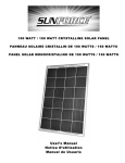
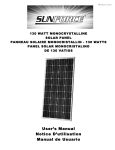
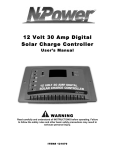
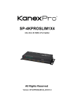
150 WATT CRYSTALLINE SOLAR PANEL
User’s Manual
Congratulations on your Sunforce Purchase. Every effort has been made to ensure this product is designed to the highest
technical specifications and standards. It should supply years of maintenance free use. Please read these instructions
thoroughly prior to installation, then store in a safe place for future reference. If at any time you are unclear about this
product, or require further assistance please do not hesitate to contact our trained professionals email to
[email protected].
Crystalline Solar Panel 150W
Power Rating: Maximum rating 150 Watts (under ideal conditions)
Current: 8.77 Amps @ 17.1 Volts
Warning:
• Avoid Electrical Hazards when installing, wiring, operating, and maintaining your Solar Module. The solar module
included generates DC electricity when exposed to sunlight or other light sources.
• For use in 12-Volt systems only
• Observe proper polarity throughout entire power cable wiring route.
• Work Safely. Do not wear jewelry when working with electrical or mechanical equipment. Use protective eyewear
when working with batteries or drills. Use extreme caution when on ladders or on roof.
• Follow all Safety Precautions of the Battery Manufacturer. Some batteries can release flammable hydrogen gas. Do not
produce sparks when working in locations where flammable gases or vapors exist. Shield skin and eyes from battery
acid. Wash thoroughly with water if skin or clothing comes into contact with acid or any corrosive matter, which may
have accumulated, on the battery. Keep the terminals and casing clean.
• Use a Charge Controller for wattages above 15 Watts
• Do not attempt to charge non-rechargeable batteries
• Always connect charge controller to battery first
• When disconnecting, always disconnect battery last
Features
• Shade tolerance
• Powerful crystalline solar technology
• Overcharge and Discharge protected
• Rugged Aluminum Frame
• Industry leading Twenty five year warranty.
• Weatherproof
• Pre-drilled installation holes
MOUNTING THE SOLAR PANEL:
Choose an appropriate location that provides the most direct sunlight and can support the solar panel, and is free from
shade. Be aware of surrounding objects; although an object seems far from the mounting location it may still obscure
the sun from the panel. The ideal year round position for a solar panel in the Northern Hemisphere is facing due south
tilted at an angle equal to your latitude. For most North American locations any angle between 30 and 50 degrees is
suitable. Note: Mounting a solar panel vertically will optimize low winter sun position but is not beneficial in the summer
months.
CONNECTION TO CHARGE CONTROLLER (Not Included)
Connect to Battery:
Connect the Solar Charge Controller (SCC) battery side positive to the positive battery terminal and the negative wire to
the negative battery terminal
Connect to Solar Panel:
Each panel comes with a Junction Box – Observe Polarity when connecting panels to controllers and/or batteries. Connect
positive to positive and negative to negative of SCC. Ensure connections are secure. Use wire nuts to connect wire to the
leads coming out of panel. Use of an experienced installer is recommended. Included Wiring is for single panel
connections. Thicker wiring required for multiple panel linking.
FAQ:
What types of batteries can I recharge?
You can recharge all types of 12 volt rechargeable batteries including lead-acid automotive batteries, deep cycle (traction
type) batteries, gel-cell batteries, and heavy duty (stationary type) batteries. When using the Solar Module to run
appliances on a regular basis, we recommend the use of deep cycle marine batteries which are designed to withstand
frequent charge and discharge cycles.
Can the Solar Module drain my battery at night?
Once the solar charge controller is installed there is no danger of reverse current, so you may leave your panel installed
overnight.
Can the Solar Module overcharge my battery?
Yes, but only if used without the charge controller. That is why it is important to use a solar charge controller. Do not
connect the panel directly to the battery with wattages of 15Watts or higher. Always use in conjunction with an
appropriately sized solar charge controller.
Can I run my 110 volt appliances with my solar power system?
Yes. You can run your 110 volt appliances with the use of an inverter, which would attach to your battery to change the
battery’s 12 volt (DC) energy into 110 volt (AC) or 220 volt (AC). Inverter is not included.
Can my panel be left outdoors without a protective covering?
Yes. The Solar Module has been weatherproofed and can be mounted outdoors without any additional protection.
Do I have to disconnect the panels from the battery when I drive my RV or while I am recharging my battery by
other means?
No, solar panels are designed to be permanently connected to the battery. There is no need to disconnect them while
driving a RV for example, or when charging the batteries by other means such as AC chargers, or a vehicle’s generator or
alternator.
GENERAL TESTING PROTOCOL
Always test outdoors under optimal sunlight conditions.
Test Solar Panels for Voltage.
Connect Voltmeter to each individual panel separately and observe Open Voltage. Open Voltage can range from 16 Volts
to 24 Volts.
Maintenance Instructions:
Cleaning of the glass may be performed by the user, utilizing a clean damp cloth.
Any other maintenance to the unit should be performed by qualified service personnel or contact our experienced
customer service team.
WARRANTY
The solar panel is covered by a Twenty five year limited warranty of 80% of power output, and must be tested under optimal
conditions. This product is warranted from defects in materials and workmanship for a period of two years from date of purchase.
This warranty does not apply in the event of misuse or abuse and or repairs and alterations.
For more information or technical support
1-888-478-6435
www.sunforceproducts.com
[email protected]
Sun150WMan_02_21_13
12 Volt 30 Amp Digital Solar
Charge Controller
User’s Manual
12 Volt 30 Amp Digital Solar Charge Controller
Maintain 12V batteries in a fully charged state
IMPORTANT SAFETY AND OPERATION INSTRUCTIONS
SAVE THESE INSTRUCTIONS
This manual contains important safety and operation instructions for the 12 Volt 30 Amp Digital
Solar Charge Controller. Keep this manual with or near the controller at all times.
The 12 Volt 30 Amp Digital Solar Charge Controller will display either the charging current or the
battery voltage on the LCD digital meter. Also, LED lights will indicate the battery condition, and
charge cycle status.
The 12 Volt 30 Amp Digital Solar Charge Controller are designed to protect your 12 Volt Lead
Acid or Gel Cell Battery from being overcharged by the solar array as well as prevent the reverse
flow of current resulting in the draining of the battery during the night. The controller reduces
overall system maintenance and prolongs the life of the battery. This controller is designed to
work with all makes of 12 Volt Solar Panels.
WARNINGS - Working with Batteries
RISK OF EXPLOSIVE GAS – Working in the vicinity of a lead acid battery is dangerous. Lead
acid batteries contain hydrogen-oxygen gases that can cause explosion and sulfuric acid that can
cause severe burns. Always work in a well ventilated area.
DO NOT SMOKE, OR ALLOW A SPARK OR A FLAME IN THE VICINITY OF A BATTERY!
Remove personal metal items such as rings, necklaces, watches, and bracelets when working
with a battery. Be extra cautious to reduce risk of dropping a metal tool on to the battery. The
battery may spark or short circuit.
NEVER CHARGE A FROZEN BATTERY
If battery acid contacts skin or clothing, wash immediately with soap and water. If acid enters the
eye, IMMEDIATELY FLOOD EYE WITH RUNNING COLD WATER for at least 10 minutes. GET
MEDICAL ATTENTION IMMEDIATELY.
Failure to comply with above warnings may lead to explosion, and or severe injury.
BE SURE TO DISCONNECT THE CONTROLLER FROM BATTERY AND SOLAR ARRAY
BEFORE PERFORMING ANY MAINTENANCE OR CLEANING
DO NOT DISSASSEMBLE THE CONTROLLER
INSTALLATION SHOULD BE PERFORMED BY A QUALIFIED PERSON
DO NOT EXCEED MAXIMUM VOLTAGE AND CURRENT RATINGS!
DO NOT DEVIATE FROM WIRING INSTRUCTIONS
Features
• Battery Voltage Tester – Battery voltage is reflected by three LED indicator lights
• Protect and maintain – Protect batteries from overcharging and maintains batteries in
fully charged state
•
Battery Type Selector – Selection of battery type, either gel cell or lead acid, for better
battery charging results
•
Safety circuit protection – protects against reverse polarity
•
Discharge protection – prevents reverse current from battery at night
•
Thermal protection – Overheat protection and auto resume
•
Terminal Block – Easy wire protection
•
Mounting Options – Panel or wall mounting
Controller Dimensions
Depth 45mm (1.77in) width 180mm (7 in) length 104mm (4.1 in)
Distance between holes for mounting 164mm (6.5 in)
Net weight is approximately 350g
Installation
Mounting - The charge controller is designed to be mounted flush with the wall.
Flush mounting requires a rectangular cutout in the mounting surface with sufficient
space (2-3 inches) behind to accommodate the controller and wiring.
The charge controller may also be mounted to the wall without making a cutout. The
controller will be raised from the wall; this is the quickest and easiest mounting
procedure.
CONNECTION DIAGRAM
Connection Procedures (please refer to the connection diagram above)
1. Once the controller has been properly mounted select either Lead – Acid or Gel –
Cell Battery modes, (refer to label below).
Caution: Do not attempt to change the battery type selector switch during charging, doing
so may affect the LCD meter reading.
2. Connect the solar panel positive side to the charge controller “ARRAY” positive (+)
with a suitable wire. Be careful not to short circuit the solar array.
3. Connect the solar panel negative side to the charge controller “ARRAY” negative (-)
with a suitable wire.
4. Connect the battery positive side to the charge controller “BATTERY” positive (+)
with a suitable wire.
5. Connect the battery negative side to the charge controller “BATTERY” negative (-)
with a suitable wire.
Please pay close attention to the following wire specifications
Wire Size
Refer to the “WIRE SIZE” chart below to determine the minimum size wire needed for
each connection. When using heavy stranded wire, you may need to divide the ends into
two groups and straddle the screw on the terminal block.
WIRE SIZE
Length of
Wire
AWG
Battery Connection Distance Round
Trip
Solar Array Connection Distance Round
Trip
not more than 0.6m (2ft)
6 or 8
6m (20ft)
10
9m (30ft)
8
12m (40ft)
6
Wire Type
It is better to use a stranded wire than a solid wire. Stranded wire does not fatigue and
cause loose connections over time as easily as solid wire. Use red wire for positive (+)
and black wire for negative (-). One 6 AWG wire (stranded) or two 8 AWG wires are
suitable. It is best to connect the wires to the controller using crimped connectors.
Ensure tight connections.
Any variation of wire size or length will affect the performance of the charge controller as
well as the LCD display.
Operation
Once properly mounted and connected the charge controller will start charging immediately given
adequate solar power. The 12 Volt 30 Amp Digital Solar Charge Controller is based on a three
stage charging algorithm, Bulk Charge Mode, Constant Voltage mode and Float Mode. During
charging period you may select the LCD meter to read either the battery voltage or charging
current at any time.
Battery condition is indicated by the LED lights. The controller will indicate the battery condition
in three states: GOOD (green), FAIR (yellow), LOW (red). Please refer to label.
Please note the charge controller is not able to start the charging process if the initial battery
voltage is less than 5 volts (+/- 0.3).
Monitoring
LED Indicator lights – please refer to label.
The top 3 LED indicator lights show the charging status of the charge controller.
The
LED (red) indicates solar power available
ON: indicates solar panel properly connected and solar power supplied within normal expectation.
OFF: indicates no power available or insufficient voltage to activate controller.
The
LED (blue) indicates the charge controller is in “Bulk Charge” mode
The
LED (green) indicates “Charge Complete” at this point the battery is fully charged
and the charge controller is in float mode.
Status
Bulk Charge
Solar Power
Weak
Float Charge
Mode
Bulk Charge
LED
Charge Complete
LED
ON
OFF
Flashes
OFF
OFF
ON
Conditions
Indicates the battery is charging. Power is being
allowed to pass through to the battery.
Indicates the solar panel voltage is too low when in
Bulk Charge mode or insufficient sunlight.
Indicates fully charged battery, a small charge
continues to pass to the battery in order to maintain
a full charge state.
The bottom 3 LED indicator lights show the state of the battery. These functions are described
below.
The
icon (green LED) indicates the battery voltage is greater than 12.5V.
The
icon (yellow LED) indicates the battery voltage is between 11.5V and 12.5V.
The
icon (red LED) indicates the battery voltage is less than 11.5V.
The
icon will blink if battery is disconnected from the unit. The charge controller will not
function if not connected to both the battery as well as the solar array. Testing may not be
performed while the charge connector is unhooked from one or both of the battery or solar array.
When Solar Power is weak as well as during the night the charger will turn off the charging LED,
indicating that charging status has been shut off in order to prevent the current back float to the
solar panel. Back Float of current may cause serious damage to the panel.
Digital LCD display meter
The digital LCD meter will continuously display battery voltage or charging current. It will not
display both at the same time. You may select either the Current or the Volt setting at any time.
Placing the slide switch in the middle turns off the LCD display meter.
Technical Specifications
Parameters
Electrical
Normal Input (Solar Cell Array voltage)
Maximum Input
Maximum charging current
Current Consumption when connected to 15 volt array (battery not present)
Current consumption when connected to a 12 volt battery (array not
present)
PWM constant voltage for Gel Cell battery
PWM constant voltage for Lead Acid battery
Float mode voltage
Data
17-22 volts
25 volts
30 amps
maximum 35mA
Maximum 25mA
14.1 volts +/-0.4
14.5 +/-0.4
13.4 +/-0.4
Battery Condition Display:
LED light indicated range
LOW (red)
FAIR (yellow)
GOOD (green)
LCD Meter Accuracy DC voltage
LCD Meter Accuracy DC current
<11.5 +/-0.4
11.5 to 12.5 +/-0.4
>12.5+/-0.4
1.25%
3%
Protection:
Over temperature protection engages at (stop charging)
Over temperature protection resets at (restart charging)
>80°C (176°F)
<65°C (149°F)
Operation Temperature
Storage Temperature
Operation Humidity Range
from -5° to 50°C (23° to 122°F)
from -10° to 70° C (14° to 158°F)
0 to 80% RH
Maintenance
The following maintenance is recommended to be performed every three months.
1.
Ensure all wire connections are sound and free from corrosion. Tighten terminal
block screws for both the solar array as well as the battery terminals.
2.
Visual check of the solar array and battery wiring for signs of overheating, damage,
and cracking. Replace any wires showing wear with new wires of the same gauge.
3.
Verify each LED status to ensure match with specifications using a voltmeter.
Troubleshooting
Battery won’t charge:
• Solar panel may be sized incorrectly. A panel with a larger output is required. You may
add on to existing panels by wiring the additional in parallel with the existing panel.
• Usage may be too high. The battery is being drawn upon at a faster rate than the panel
is able to produce. A secondary battery may be used, by physically switching the
batteries out and allowing one battery to supply power while the other is being charged.
• Battery may be too small. In this case it may appear the battery is not charging however
it is the reserve that is depleting too quickly. A battery with a larger capacity may be
required. A secondary battery may be used, either by physically switching the batteries
out and allowing one battery to supply power while the other is being charged or using a
battery isolator. A second battery may also be added to the existing battery by wiring the
additional battery in parallel to the existing battery. The charge controller need only be
connected to one of the batteries in this case.
• The battery may be bad. Small level of charge or discharge will greatly affect the battery
voltage. Battery needs replacing.
•
•
•
Wires may be incorrectly hooked to the charge controller. Ensure the wires are
connected in parallel to the controller and to the correct terminals.
Solar Panel has no output:
The solar panel may be seriously affected by the angle of the panel with regards to the
sun, and environmental factors. Ensure the surface is clean and free of dust and build
up; a clean damp rag may be used to clear the panel of dust. Do not use soap or
solvents of any kind. Cloudy conditions will affect the output of the solar panel.
Wires may be incorrectly hooked to the charge controller. Ensure the wires are
connected in parallel to the controller and to the correct terminals. Please refer to the
Connection Procedures portion of this manual.
Warranty
This product is covered by a 1 year limited warranty. Sunforce Products Inc warrants to the original purchaser that this
product is free from defects in materials and workmanship for the period of one year from date of purchase
To obtain warranty service please contact Sunforce Products for further instruction, at 1-888-478-6435 or email
[email protected]. Proof of purchase including date, and an explanation of complaint is required for warranty
service.
For more information or technical support
1-888-478-6435
www.sunforceproducts.com
[email protected]
30ADCC081512
300 Watt
MODIFIED SINE WAVE INVERTER
User Manual
Congratulations on your Sunforce Products purchase. This product is designed to the highest technical
specifications and standards. It will supply years of maintenance free use. Please read these instructions
thoroughly prior to installation, then store in a safe place for future reference. If at any time you are unclear
about this product, or require further assistance please do not hesitate to contact our trained professionals.
Email [email protected].
SPECIFICATIONS :
Max. Continuous Power / Surge Capability (Peak Power) : 300Watt (± 25W) / 600Watt
No Load Current Draw : < 0.3A
Wave form : Modified Sine Wave
Input Voltage Range : 10 - 15 VDC
AC outlets : 110V AC 2 prong grounded
YOUR POWER INVERTER
A Power inverter is used to convert 12 Volts DC from a battery into 110 Volts AC.
Most electronic items have a power consumption listed as standard. This consumption (load) listed in
wattage will allow you to determine if you can utilize your 300 watt inverter.
Some items have a large starting load this should be under the rated surge capacity of the inverter (600
Watt)
In the event of a power overload, the inverter is designed to automatically shut and emitt a loud beep.
This safety feature prevents damaging the unit. The RED LED will iluminate at this time
IMPORTANT:
* Make sure you connect your inverter to a 12 volt battery only.
Do not attempt to connect the inverter to any other power source, including any AC power source or
directly to a solar panel.
* Do not try extending or otherwise changing the 12 volt power cord attached to your inverter.
FUNCTIONS
A. ON/OFF Rocker Switch
B. LED Indicator Light. (Green = Power On, Red = Overload )
C. 2 X 110V AC Outlets
D. High-speed Cooling Fan
E. Fuse
F. 12V DC Plug (300W)
F
G. Power Input Terminal (Black = Neg, Red = Pos)
I. USB Port
D
300W
E
C
A
B
I
How To Connect Inverter
1. Make sure the ON/OFF rocker switch (see diagram, part A) is in the OFF (0) position.
2. Connect the inverter connection cable to your 12 Volt battery .
3. Ensure you have correct polarity between the battery and inverter. Only use the supplied connection
cables
3. Push the 12 volt power plug from the inverter firmly into the outlet
4. Turn on the inverter, the GREEN LED should now illuminate
Using the USB outlet
1. Make sure the ON/OFF rocker switch (see diagram, part A) is in the OFF (0) position.
2. Connect your USB device to the power inverter
3. Turn ON the inverter and begin charging
Important Safety Measures
* For the most effective use, place the power inverter on a flat surface.
* Keep the inverter dry.
* Do not allow it to come into contact with rain or moisture.
* DO NOT operate the inverter if you, the inverter, or the device being operated, or any other surfaces that
may come
* Do not place the inverter on or near heating vents, radiators or other sources of heat.
* Do not place the inverter in direct sunlight. The ideal air temperature for operation is between 50o F and
80o F
* Keep the inverter well ventilated in order to properly disperse heat generated while it is in use.
* While in use, make sure there are several inches of clearance around the top and sides of the inverter.
* Do not use the inverter near flammable materials.
* Do not place the inverter in areas such as battery box’s where fumes or gases may accumulate.
Trouble Shooting
Problem
Low or No
Output voltage
Reason
- Poor contact with 12V DC plug.
- Using incorrect type of voltmeter to test
output voltage
Red LED on
- Battery voltage below 10 volts.
- Equipment being operated is drawing too
much power.
- Inverter is too hot (thermal shutdown
mode)
Low Battery
Alarm
On ALL The Time
- Input voltage below 10 volts.
- Poor or weak battery condition.
- Inadequate power being delivered to the
inverter or
excessive voltage drop.
Solution
- Unplug and reinsert 12V DC
Plug
- Use a true RMS reading
meter.
- Recharge or replace battery.
- Use a higher capacity inverter
or do not use this equipment.
- Allow inverter to cool.
Check for adequate ventilation.
Reduce the load on the inverter
to read continuous power
output.
- Recharge or replace battery to
maintain adequate power input.
- Recharge or replace battery.
- Check condition of 12 Volt
socket
socket. Clean or replace if
necessary.
Limited Warranty
This product is covered by a one year limited warranty. Sunforce Products Inc warrants to the original
purchaser that this product is free from defects in materials and workmanship for the period of one year
from date of purchase. This warranty does not apply in the event of misuse or abuse of the product or as a
result of unauthorized repairs or alterations.
To obtain warranty service please contact Sunforce Products for further instruction, at 1-888-478-6435 or
email [email protected]. Proof of purchase including date, and an explanation of complaint is
required for warranty service.