1
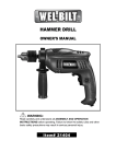
12 Volt 30 Amp Digital
Solar Charge Controller
User’s Manual
WARNING
Read carefully and understand all INSTRUCTIONS before operating. Failure
to follow the safety rules and other basic safety precautions may result in
seriouse personal injury.
ITEM# 121070
12 Volt 30 Amp Digital Solar Charge Controller
Maintain 12V batteries in a fully charged state
IMPORTANT SAFETY AND OPERATION INSTRUCTIONS
SAVE THESE INSTRUCTIONS
This manual contains important safety and operation instructions for the 12 Volt 30 Amp Digital
Solar Charge Controller. Keep this manual with or near the controller at all times.
The 12 Volt 30 Amp Digital Solar Charge Controller will display either the charging current or the
battery voltage on the LCD digital meter. Also, LED lights will indicate the battery condition, and
charge cycle status.
The 12 Volt 30 Amp Digital Solar Charge Controller are designed to protect your 12 Volt Lead
Acid or Gel Cell Battery from being overcharged by the solar array as well as prevent the reverse
flow of current resulting in the draining of the battery during the night. The controller reduces
overall system maintenance and prolongs the life of the battery. This controller is designed to
work with all makes of 12 Volt Solar Panels.
WARNINGS - Working with Batteries
RISK OF EXPLOSIVE GAS – Working in the vicinity of a lead acid battery is dangerous. Lead
acid batteries contain hydrogen-oxygen gases that can cause explosion and sulfuric acid that can
cause severe burns. Always work in a well-ventilated area.
DO NOT SMOKE, OR ALLOW A SPARK OR A FLAME IN THE VICINITY OF A BATTERY!
Remove personal metal items such as rings, necklaces, watches, and bracelets when working
with a battery. Be extra cautious to reduce risk of dropping a metal tool on to the battery. The
battery may spark or short circuit.
NEVER CHARGE A FROZEN BATTERY
If battery acid contacts skin or clothing, wash immediately with soap and water. If acid enters the
eye, IMMEDIATELY FLOOD EYE WITH RUNNING COLD WATER for at least 10 minutes. GET
MEDICAL ATTENTION IMMEDIATELY.
Failure to comply with above warnings may lead to explosion, and or severe injury.
BE SURE TO DISCONNECT THE CONTROLLER FROM BATTERY AND SOLAR ARRAY
BEFORE PERFORMING ANY MAINTENANCE OR CLEANING
DO NOT DISSASSEMBLE THE CONTROLLER
INSTALLATION SHOULD BE PERFORMED BY A QUALIFIED PERSON
DO NOT EXCEED MAXIMUM VOLTAGE AND CURRENT RATINGS!
DO NOT DEVIATE FROM WIRING INSTRUCTIONS
Features
• Battery Voltage Tester – Battery voltage is reflected by three LED indicator lights
• Protect and maintain – Protect batteries from overcharging and maintains batteries in
fully charged state
•
Battery Type Selector – Selection of battery type, either gel cell or lead acid, for better
battery charging results
•
Safety circuit protection – protects against reverse polarity
•
Discharge protection – prevents reverse current from battery at night
•
Thermal protection – Overheat protection and auto resume
•
Terminal Block – Easy wire protection
•
Mounting Options – Panel or wall mounting
Controller Dimensions
Depth 45mm (1.77in) width 180mm (7 in) length 104mm (4.1 in)
Distance between holes for mounting 164mm (6.5 in)
Net weight is approximately 350g
Installation
Mounting - The charge controller is designed to be mounted flush with the wall.
Flush mounting requires a rectangular cutout in the mounting surface with sufficient
space (2-3 inches) behind to accommodate the controller and wiring.
The charge controller may also be mounted to the wall without making a cutout. The
controller will be raised from the wall; this is the quickest and easiest mounting
procedure.
CONNECTION DIAGRAM
Connection Procedures (please refer to the connection diagram above)
1. Once the controller has been properly mounted select either Lead – Acid or Gel –
Cell Battery modes, (refer to label below).
Caution: Do not attempt to change the battery type selector switch during charging,
doing so may affect the LCD meter reading.
2. Connect the solar panel positive side to the charge controller “ARRAY” positive (+)
with a suitable wire. Be careful not to short circuit the solar array.
3. Connect the solar panel negative side to the charge controller “ARRAY” negative (-)
with a suitable wire.
4. Connect the battery positive side to the charge controller “BATTERY” positive (+)
with a suitable wire.
5. Connect the battery negative side to the charge controller “BATTERY” negative (-)
with a suitable wire.
Please pay close attention to the following wire specifications
Wire Size
Refer to the “WIRE SIZE” chart below to determine the minimum size wire needed for
each connection. When using heavy stranded wire, you may need to divide the ends into
two groups and straddle the screw on the terminal block.
WIRE SIZE
Length of
Wire
AWG
Battery Connection Distance Round
Trip
Solar Array Connection Distance Round
Trip
not more than 0.6m (2ft)
6 or 8
6m (20ft)
10
9m (30ft)
8
12m (40ft)
6
Wire Type
It is better to use a stranded wire than a solid wire. Stranded wire does not fatigue and
cause loose connections over time as easily as solid wire. Use red wire for positive (+)
and black wire for negative (-). One 6 AWG wire (stranded) or two 8 AWG wires are
suitable. It is best to connect the wires to the controller using crimped connectors.
Ensure tight connections.
Any variation of wire size or length will affect the performance of the charge controller as
well as the LCD display.
Operation
Once properly mounted and connected the charge controller will start charging immediately given
adequate solar power. The 12 Volt 30 Amp Digital Solar Charge Controller is based on a three
stage charging algorithm, Bulk Charge Mode, Constant Voltage mode and Float Mode. During
charging period you may select the LCD meter to read either the battery voltage or charging
current at any time.
Battery condition is indicated by the LED lights. The controller will indicate the battery condition
in three states: GOOD (green), FAIR (yellow), LOW (red). Please refer to label.
Please note the charge controller is not able to start the charging process if the initial battery
voltage is less than 5 volts (+/- 0.3).
Monitoring
LED Indicator lights – please refer to label.
The top 3 LED indicator lights show the charging status of the charge controller.
LED (red) indicates solar power available
The
ON: indicates solar panel properly connected and solar power supplied within normal expectation.
OFF: indicates no power available or insufficient voltage to activate controller.
The
LED (blue) indicates the charge controller is in “Bulk Charge” mode
LED (green) indicates “Charge Complete” at this point the battery is fully charged
The
and the charge controller is in float mode.
Status
Bulk Charge
Solar Power
Weak
Float Charge
Mode
Bulk Charge
LED
Charge Complete
LED
ON
OFF
Flashes
OFF
OFF
ON
Conditions
Indicates the battery is charging. Power is being
allowed to pass through to the battery.
Indicates the solar panel voltage is too low when in
Bulk Charge mode or insufficient sunlight.
Indicates fully charged battery, a small charge
continues to pass to the battery in order to maintain
a full charge state.
The bottom 3 LED indicator lights show the state of the battery. These functions are described
below.
The
icon (green LED) indicates the battery voltage is greater than 12.5V.
The
icon (yellow LED) indicates the battery voltage is between 11.5V and 12.5V.
The
icon (red LED) indicates the battery voltage is less than 11.5V.
icon will blink if battery is disconnected from the unit. The charge controller will not
The
function if not connected to both the battery as well as the solar array. Testing may not be
performed while the charge connector is unhooked from one or both of the battery or solar array.
When Solar Power is weak as well as during the night the charger will turn off the charging LED,
indicating that charging status has been shut off in order to prevent the current back float to the
solar panel. Back Float of current may cause serious damage to the panel.
Digital LCD display meter
The digital LCD meter will continuously display battery voltage or charging current. It will not
display both at the same time. You may select either the Current or the Volt setting at any time.
Placing the slide switch in the middle turns off the LCD display meter.
Technical Specifications
Parameters
Electrical
Normal Input (Solar Cell Array voltage)
Maximum Input
Maximum charging current
Current Consumption when connected to 15 volt array (battery not present)
Current consumption when connected to a 12 volt battery (array not
present)
PWM constant voltage for Gel Cell battery
PWM constant voltage for Lead Acid battery
Float mode voltage
Battery Condition Display:
LED light indicated range
LOW (red)
FAIR (yellow)
GOOD (green)
LCD Meter Accuracy DC voltage
Data
17-22 volts
25 volts
30 amps
maximum 35mA
Maximum 25mA
14.1 volts +/-0.4
14.5 +/-0.4
13.4 +/-0.4
<11.5 +/-0.4
11.5 to 12.5 +/-0.4
>12.5+/-0.4
1.25%
LCD Meter Accuracy DC current
3%
Protection:
Over temperature protection engages at (stop charging)
Over temperature protection resets at (restart charging)
>80°C (176°F)
<65°C (149°F)
Operation Temperature
Storage Temperature
Operation Humidity Range
from -5° to 50°C (23° to 122°F)
from -10° to 70° C (14° to 158°F)
0 to 80% RH
Maintenance
The following maintenance is recommended to be performed every three months.
1.
Ensure all wire connections are sound and free from corrosion. Tighten terminal
block screws for both the solar array as well as the battery terminals.
2.
Visual check of the solar array and battery wiring for signs of overheating, damage,
and cracking. Replace any wires showing wear with new wires of the same gauge.
3.
Verify each LED status to ensure match with specifications using a voltmeter.
Troubleshooting
Battery won’t charge:
• Solar panel may be sized incorrectly. A panel with a larger output is required. You may
add on to existing panels by wiring the additional in parallel with the existing panel.
• Usage may be too high. The battery is being drawn upon at a faster rate than the panel
is able to produce. A secondary battery may be used, by physically switching the
batteries out and allowing one battery to supply power while the other is being charged.
• Battery may be too small. In this case it may appear the battery is not charging however
it is the reserve that is depleting too quickly. A battery with a larger capacity may be
required. A secondary battery may be used, either by physically switching the batteries
out and allowing one battery to supply power while the other is being charged or using a
battery isolator. A second battery may also be added to the existing battery by wiring the
additional battery in parallel to the existing battery. The charge controller need only be
connected to one of the batteries in this case.
• The battery may be bad. Small level of charge or discharge will greatly affect the battery
voltage. Battery needs replacing.
• Wires may be incorrectly hooked to the charge controller. Ensure the wires are
connected in parallel to the controller and to the correct terminals.
Solar Panel has no output:
• The solar panel may be seriously affected by the angle of the panel with regards to the
sun, and environmental factors. Ensure the surface is clean and free of dust and build
up; a clean damp rag may be used to clear the panel of dust. Do not use soap or
solvents of any kind. Cloudy conditions will affect the output of the solar panel.
• Wires may be incorrectly hooked to the charge controller. Ensure the wires are
connected in parallel to the controller and to the correct terminals. Please refer to the
Connection Procedures portion of this manual.
Warranty
This product is covered by a 2 year limited warranty. N’Power Product's will warrant to the original
purchaser that this product is free from defects in materials and workmanship for the period of
two years from date of purchase.
To obtain warranty service please contact N’Power Products for further instruction, at 1-800-2225381. Proof of purchase including date, and an explanation of complaint is required for warranty
service. Distributed by Northern Tool + Equipment Company 2800 South cross Drive Burnsville,
MN 55306
www.northerntool.com
(04_22_10)