1
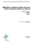
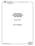
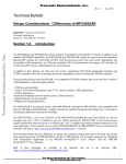
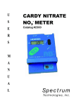
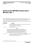
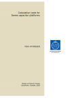
Order Number: MPC857TUMAD/D
Rev. 0, 6/2001
Semiconductor Products Sector
™
Errata to
MPC857T PowerQUICC™ User’s Manual Rev. 0
This errata describes corrections to revision 0 of the MPC857T PowerQUICC User’s
Manual (order number: MPC857TUMAD/D, Rev. 0).
This document contains information on a new product under development by
Motorola. Motorola reserves the right to change or discontinue this product without
© Motorola, Inc., 2001. All rights reserved.
Section #/Page #
10.10.1, 10-28
Changes
In Figure 10-24, the reset value of the RTCSC should be replaced with
the following:
0000_0000_000x_00xx.
11.1.3.1, 11-3
Add the following note:
NOTE:
The PLL loss of lock detection does not have a specification
for the detection threshold. Therefore it should used solely as
a debug tool and not in production systems. Characterization
of the threshold value over temperature and operating voltages
has shown that the threshold can be triggered when clock out
to clock in phase differences is 1.8 ns. or more.
11.3.1.1, 11-9
Add BBE (boot burst enable) to bit 2, and CLES (core little endian
swap) to bit 15 of Figure 11-8 and add the following description to
Table 11-3:
Table 11-3. Hard Reset Configuration Word Field Descriptions
Bits Name
Description
2
BBE
Boot Burst Enable
0 The boot device does not support bursting.
1 The boot device does support bursting.
15
CLES
Core Little Endian Swap. Defines core access operation following reset.
0 Big Endian
1 Little Endian
12.1, global
Table 12-1. Add the following signals:
B7 M_CRS
H18 M_MDIO
V15 M_TXEN
H4 M_COL
W15 M_TX_CLK
For a complete listing of VDDL, VDDH, and GND, see the
document MPC857T Family Hardware Specifications
(MPC857TEC/D). The information provided in the Hardware
Specification supersedes all information found in the
MPC857T UM.
2
Errata to the MPC857T PowerQUICC User’s Manual Rev 0
Section #/Page #
14.2.2.3, 14-8
Changes
Replace Table 14-2 with the following:
Table 14-2. XFC Capacitor Values Based on PLPRCR[MF]
MF Range
Minimum Capacitance
1 ≤ (MF+1) ≤ 4 XFC = [(MF+1) x 580] - 100
(MF+1) > 4
XFC = (MF+1) x 830
15.4.1,15-9
Recommended Capacitance
Maximum Capacitance
Unit
XFC = [(MF+1) x 680] - 120
XFC = [(MF+1) x 780] - 140
pF
XFC = (MF+1) X 1100
XFC = (MF+1) x 1470
pF
In Figure 16-5, replace the reset values of BRx with the following:
xxxx_xxxx_xxxx_xxxx_xxxx_xxxx_xx00_0000.
In Figure 16-6, replace the reset values of the first five nibbles of BR0
with xxxx_xxxx_xxxx_xxxx_xxxx, and add the following footnote:
Since the base address values are unknown at reset, to ensure
proper operation, program the base address before
programming the Option Register.
15.4.2, 15-11
In Figure 16-7, replace the reset values of ORx with the following:
xxxx_xxxx_xxxx_xxxx_xxxx_xxxx_xxxx_xxx0.
Replace the text after Figure 16-7 with the following:
At reset, OR0 has specific default values and is read-only, as
shown in Figure 15-8. After reset, OR0 becomes R/W.
15.4.4, 15-14
In Figure 16-10, replace the reset values of the first two nibbles of
MxMR with the following:
xxxx_xxxx
15.4.5, 15-15
In Figure 16-11, replace the reset values of the MCR with the
following:
xx00_0000_x000_0000_xxx0_xxxx_00xx_xxxx.
15.4.6, 15-16
In Figure 16-12, replace the reset values of the MDR with the
following:
xxxx_xxxx_xxxx_xxxx_xxxx_xxxx_xxxx_xxxx.
15.4.7, 15-17
In Figure 16-13, replace the reset values of the MAR with the
following:
xxxx_xxxx_xxxx_xxxx_xxxx_xxxx_xxxx_xxxx.
Errata to the MPC857T PowerQUICC User’s Manual Rev 0
3
Section #/Page #
16.4, 16-8
Changes
Replace sections 16.4, and16.4.1 through 16.4.3 with the following:
16.4 Programming Model
This section describes the PCMCIA interface programming model. Generally, all registers
are memory-mapped within the internal control register area. The registers in Table 16-7
control the PCMCIA interface.
Table 16-7 PCMCIA Registers
Name
Description
PIPR
PCMCIA interface input pins register
PSCR
PCMCIA interface status changed register
PER
PCMCIA interface enable register
PGCRA
PCMCIA interface general control register a
PGCRB
PCMCIA interface general control register b
PBR[0–7]
PCMCIA base registers 0–7 (per window)
POR[0–7]
PCMCIA option registers 0–7 (per window)
16.4.1 PCMCIA Interface Input Pins Register (PIPR)
Status of inputs from the PCMCIA card to the host (BVD, CD, RDY, VS) is reported to the
PIPR, shown in Figure 16-3. PIPR is a read-only register; write operations are ignored.
Bit
Field
0
1
2
3
4
5
6
8
9
CAVS1 CAVS2 CAWP CACD2 CACD1 CABVD2 CABVD1 CARDY
Reset
Undefined
R/W
R
Addr
Bit
7
10 11 12 13 14 15
—
(IMMR & 0xFFFF0000) + 0x0F0
16
17
18
19
20
21
22
23
24 25 26 27 28 29 30 31
Field CBVS1 CBVS2 CBWP CBCD2 CBCD1 CBBVD2 CBBVD1 CBRDY
Reset
Undefined
R/W
R
Addr
(IMMR & 0xFFFF0000) + 0x0F2
—
Figure 16-3. PCMCIA Interface Input Pins Register (PIPR)
4
Errata to the MPC857T PowerQUICC User’s Manual Rev 0
Section #/Page #
Changes
Table 16-8 describes PIPR fields.
Table 16-8. PIPR Field Descriptions
Bits
Name
0
CAVS1
Voltage sense 1 for card A
Description
1
CAVS2
Voltage sense 2 for card A
2
CAWP
Write protect for card A
3
CACD2
Card detect 2 for card A
4
CACD1
Card detect 1 for card A
5
CABVD2 Battery voltage/SPKR_A input for card A
6
CABVD1 Battery voltage/STSCHG_A input for card A
7
CARDY
RDY/IRQ of card A pin
8–15
—
16
CBVS1
Voltage sense 1 for card B
17
CBVS2
Voltage sense 2 for card B
18
CBWP
Write protect for card B
19
CBCD2
Card detect 2 for card B
CBCD1
Card detect 1 for card B
20
Reserved, should be cleared.
21
CBBVD2 Battery voltage/SPKR_B input for card B
22
CBBVD1 Battery voltage/STSCHG_B input for card B
23
CBRDY
24–31
—
RDY/IRQ of card B pin
Reserved, should be cleared.
16.4.2 PCMCIA Interface Status Changed Register (PSCR)
The contents of PSCR, shown in Figure 16-4, are logically ANDed with the PER to
generate a PCMCIA interface interrupt. Writing zeros has no effect; writing ones clears the
corresponding interrupt state.
Errata to the MPC857T PowerQUICC User’s Manual Rev 0
5
Section #/Page #
Changes
Bit
0
1
2
3
4
5
Field
CAVS1_
C
CAVS2_
C
CAWP_
C
CACD2_
C
CACD1_
C
CABVD2_
C
6
Reset
Undefined
R/W
R/W
Addr
7
8
9
CABVD1_ — CARDY_L CARDY_
C
H
10
12–15
—
(IMMR & 0xFFFF0000) + 0x0E8
Bit
16
17
18
19
20
21
Field
CBVS1_
C
CBVS2_
C
CBWP_
C
CBCD2_
C
CBCD1_
C
CBBVD2_
C
22
2
3
24
25
CBBVD1_ — CBRDY_L CBRDY_
C
H
Reset
Undefined
R/W
R/W
Addr
(IMMR & 0xFFFF0000) + 0x0EA
26
Table 16-9 describes PSCR fields.
Table 16-9. PSCR Field Descriptions
Bits
Name
0
CAVS1_C
Voltage sense 1 for card A changed
1
CAVS2_C
Voltage sense 2 for card A changed
2
CAWP_C
Write protect for card A changed
3
CACD2_C
Card detect 2 for card A changed
4
CACD1_C
Card detect 1 for card A changed
5
CABVD2_C
Description
Battery voltage/SPKR_A input for card A changed
Battery voltage/STSCHG_A input for card A changed
6
CABVD1_C
7
—
8
CARDY_L
RDY/IRQ of card A pin is low. Device and socket interrupt.
Reserved, should be cleared.
9
CARDY_H
RDY/IRQ of card A pin is high. Device and socket interrupt.
10
CARDY_R
RDY/IRQ of card A pin rising edge detected. Device and socket interrupt.
RDY/IRQ of card A pin falling edge detected. Device and socket interrupt.
11
CARDY_F
12–15
—
16
CBVS1_C
Voltage sense 1 for card B changed
17
CBVS2_C
Voltage sense 2 for card B changed
18
CBWP_C
Write Protect for card B changed
19
CBCD2_C
Card detect 2 for card B changed
20
CBCD1_C
21
CBBVD2_C
22
CBBVD1_C
23
—
Reserved, should be cleared.
Card detect 1 for card B changed
Battery voltage/SPKR_B input for card B changed
Battery voltage/STSCHG_B input for card B changed
Reserved, should be cleared.
Errata to the MPC857T PowerQUICC User’s Manual Rev 0
27
CBRDY_ CBRDY_F
R
Figure 16-4. PCMCIA Interface Status Changed Register (PSCR)
6
11
CARDY_ CARDY_F
R
28–31
—
Section #/Page #
Changes
Table 16-9. PSCR Field Descriptions (Continued)
Bits
Name
Description
24
CBRDY_L
RDY/IRQ of card B pin is low. Device and socket interrupt.
25
CBRDY_H
RDY/IRQ of card B pin is high. Device and socket interrupt.
26
CBRDY_R
RDY/IRQ of card B pin rising edge detected. Device and socket interrupt.
27
CBRDY_F
28–31
—
RDY/IRQ of card B pin falling edge detected. Device and socket interrupt.
Reserved, should be cleared.
16.4.3 PCMCIA Interface Enable Register (PER)
Setting a bit in the PER, shown in Figure 16-5, enables the corresponding interrupt.
Bit
0
Field
CA_EV
S1
1
2
3
CA_EV CA_EW CA_EC
S2
P
D2
4
5
CA_EC
D1
CA_EBV
D2
6
7
Rese
t
0000_0000_0000_0000
R/W
R/W
Addr
8
9
10
11
12-15
CA_EBV — CA_ERDY CA_ERDY_ CA_ERDY_ CA_ERDY
D1
_L
H
R
_F
—
(IMMR & 0xFFFF0000) + 0x0F8
Bit
16
17
Field
CB_EV
S1
18
19
CB_EV CB_EW CB_EC
S2
P
D2
20
21
CB_EC
D1
CB_EBV
D2
22
2
3
24
25
26
27
28-31
CB_EBV — CB_ERDY CB_ERDY_ CB_ERDY_ CB_ERDY
D1
_L
H
R
_F
Rese
t
0000_0000_0000_0000
R/W
R/W
Addr
(IMMR & 0xFFFF0000) + 0x0FA
—
Figure 16-5. PCMCIA Interface Enable Register (PER)
Table 16-10 describes PER fields.
Table 16-10. PER Field Descriptions
Bits
Name
Description
0
CA_EVS1
Enable for voltage sense 1 for card A changed. Setting this bit enables the interrupt on any
signal change.
1
CA_EVS2
Enable for voltage sense 2 for card A changed. Setting this bit enables the interrupt on any
signal change.
2
CA_EWP
Enable for write protect for card A changed. Setting this bit enables the interrupt on any signal
change.
3
CA_ECD2
Enable for card detect 2 for card A changed. Setting this bit enables the interrupt on any
signal change.
4
CA_ECD1
Enable for card detect 1 for card A changed. Setting this bit enables the interrupt on any
signal change.
Errata to the MPC857T PowerQUICC User’s Manual Rev 0
7
Section #/Page #
Changes
Table 16-10. PER Field Descriptions (Continued)
Bits
Name
5
CA_EBVD2
Enable for battery voltage/SPKR_A input for card A changed. Setting this bit enables the
interrupt on any signal change.
6
CA_EBVD1
Enable for battery voltage/STSCHG_A input for card A changed.
7
—
8
CA_ERDY_L
Description
Reserved, should be 0.
Enable for RDY/IRQ of card A pin is low
9
CA_ERDY_H Enable for RDY/IRQ card A pin is high
10
CA_ERDY_R Enable for RDY/IRQ card A pin rising edge detected
11
CA_ERDY_F Enable for RDY/IRQ card A pin falling edge detected
12–15
—
16
CB_EVS1
Reserved, should be 0.
Enable for voltage sense 1 for card B changed. Setting this bit enables the interrupt on any
signal change.
17
CB_EVS2
Enable for voltage sense 2 for card B changed. Setting this bit enables the interrupt on any
signal change.
18
CB_EWP
Enable for write protect for card B changed. Setting this bit enables the interrupt on any signal
change.
19
CB_ECD2
Enable for card detect 2 for card B changed. Setting this bit enables the interrupt on any
signal change.
20
CB_ECD1
Enable for card detect 1 for card B changed. Setting this bit enables the interrupt on any
signal change.
21
CB_EBVD2
Enable for battery voltage/SPKR_B input for card B changed. Setting this bit enables the
interrupt on any signal change.
22
CB_EBVD1
23
—
Enable for battery voltage/STSCHG_B input for card B changed
Reserved, should be 0.
Enable for RDY/IRQ of card B pin is low
24
CB_ERDY_L
25
CB_ERDY_H Enable for RDY/IRQ card B pin is high
26
CB_ERDY_R Enable for RDY/IRQ card B pin rising edge detected
27
CB_ERDY_F Enable for RDY/IRQ card B pin falling edge detected
28–31
—
33.5.1.3, 33-21
Reserved, should be 0.
The final sentence in this section should be replaced with the
following:
The Fast Ethernet Controller is described in Part VII, Chapter
43, “Fast Ethernet Controller (FEC).”
35, 35-1
Remove this sentence:
When not in ESAR mode, the MPC857T remains backwards
compatible to the classic SAR ATM operation of the
MPC860SAR.
8
Errata to the MPC857T PowerQUICC User’s Manual Rev 0
Section #/Page #
42.1,42-1
Changes
Remove this from the feature list:
Back compatible with MPC860SAR UTOPIA muxed bus.
Ch. 43, global
FEC (Fast Ethernet Controller)
R_FSTART should show bits 16-31 as address 0xED2
X_WMRK should show bits 0-15 as address 0xEE4
X_WMRK should show bits 16-31 as address 0xEE6
R_CNTRL should show bits 0-15 as address 0xF44
R_CNTRL should show bits 16-31 as address 0xF46
Errata to the MPC857T PowerQUICC User’s Manual Rev 0
9
DigitalDNA is a trademark of Motorola, Inc.
The PowerPC name, the PowerPC logotype, and PowerPC 603e are trademarks of International Business Machines Corporation used by Motorola
under license from International Business Machines Corporation.
Information in this document is provided solely to enable system and software implementers to use PowerPC microprocessors. There are no express
or implied copyright licenses granted hereunder to design or fabricate PowerPC integrated circuits or integrated circuits based on the information in
this document.
Motorola reserves the right to make changes without further notice to any products herein. Motorola makes no warranty, representation or guarantee
regarding the suitability of its products for any particular purpose, nor does Motorola assume any liability arising out of the application or use of any
product or circuit, and specifically disclaims any and all liability, including without limitation consequential or incidental damages. “Typical” parameters
can and do vary in different applications. All operating parameters, including “Typicals” must be validated for each customer application by customer’s
technical experts. Motorola does not convey any license under its patent rights nor the rights of others. Motorola products are not designed, intended,
or authorized for use as components in systems intended for surgical implant into the body, or other applications intended to support or sustain life,
or for any other application in which the failure of the Motorola product could create a situation where personal injury or death may occur. Should Buyer
purchase or use Motorola products for any such unintended or unauthorized application, Buyer shall indemnify and hold Motorola and its officers,
employees, subsidiaries, affiliates, and distributors harmless against all claims, costs, damages, and expenses, and reasonable attorney fees arising
out of, directly or indirectly, any claim of personal injury or death associated with such unintended or unauthorized use, even if such claim alleges that
Motorola was negligent regarding the design or manufacture of the part.
Motorola and
are registered trademarks of Motorola, Inc. Motorola, Inc. is an Equal Opportunity/Affirmative Action Employer.
Motorola Literature Distribution Centers:
USA/EUROPE: Motorola Literature Distribution; P.O. Box 5405; Denver, Colorado 80217; Tel.: 1-800-441-2447 or 1-303-675-2140;
World Wide Web Address: http://ldc.nmd.com/
JAPAN: Nippon Motorola Ltd SPD, Strategic Planning Office 4-32-1, Nishi-Gotanda Shinagawa-ku, Tokyo 141, Japan Tel.: 81-3-5487-8488
ASIA/PACIFIC: Motorola Semiconductors H.K. Ltd Silicon Harbour Centre 2, Dai King Street Tai Po Industrial Estate Tai Po, New Territories, Hong
Kong
World Wide Web Address: http://sps.motorola.com/mfax
INTERNET: http://motorola.com/sps
Technical Information: Motorola Inc. SPS Customer Support Center 1-800-521-6274; electronic mail address: [email protected].
Document Comments: FAX (512) 933-2526, Attn: RISC Applications Engineering.
World Wide Web Addresses: http://www.motorola.com/PowerPC
http://www.motorola.com/netcomm
http://www.motorola.com/Coldfire
MPC857TUMAD/D