1
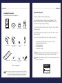
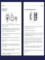
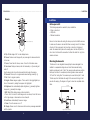
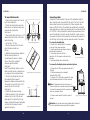
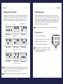
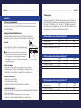
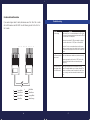
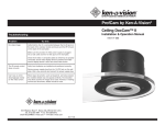
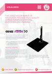
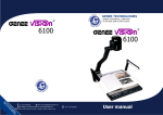
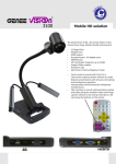
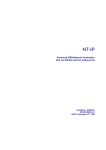
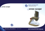
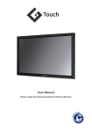
GENEE TECHNOLOGIES
INDIA PRIVATE LIMITED
An ISO 9001:2008 certified company
Genee Air by Genee Vision
Ceiling mounted visualiser
Installation & Operation Manual
Classroom for the Future
Tel: 0124-4934500
@ Email: [email protected]
WWW Website: www.genee-india.com, www.geneeworld.com
Plot No. 698, Udog Vihar, Phase V, Gurgaon, Harana-122016, India
Fax: 0124-4934521
User manual
Table of Contents................................................................................
Table of Contents
Introduction................................................................................ 3
Services and support................................................................... 3
Product returns........................................................................... 3
Unpacking.................................................................................. 4
Important safeguards................................................................... 5
Product overview........................................................................ 6
Installation................................................................................. 9
Before you install........................................................................ 9
Mounting the camera................................................................... 10
Connecting cables ...................................................................... 11
Configuring for remote controls..................................................... 12
Programming presents................................................................. 13
Operation.................................................................................. 14
Using your codec remote............................................................. 14
Using your ClearOne remote......................................................... 14
Viewing areas............................................................................. 15
Custom cable information............................................................. 16
Troubleshooting.......................................................................... 17
..........................................................................................Introduction
Introduction
The Genee Air is a ceiling-mounted visualiser that displays images on monitors,
plasma screens,video projectors and videoconferencing systems. It is ideal for
presenting or sharing any type of object or document, from detailed images to large
blueprints. The camera is installed in the ceiling above a conference table and has
a low profile design that is appropriate for any room decor. Additional features
include:
• Laser pointer providing accurate document position.
• Single cable carrying power, video and control, simplifying installation and connection.
• IR remote with increased functionality including zooming presets, brightness control and laser operation.
• User accessible DIP switches that allow the Genee Air to respond to different
video codec remotes.
Professional Services
If you need any additional information on how to install, set up, or operate your
camera, please contact us. We welcome and encourage your comments so we can
continue to improve our products and serve your needs.
Corporate Headquarters:
PO Box 3256
Wolverhampton, WV3 OLA, United Kingdom
Tel.: +44 (0)870 386 1900
Fax: +44 (0)870 405 0188
Email: [email protected]
Website: www.geneeworld.com
Product registration
Please register your visualiser using the online registration form in the Product
section at www.geneeworld.com. We are better able to provide technical assistance when your product is properly registered. Registration information is also used
to notify you of upgrades and new product information.
Product returns
All product returns require a return authorization (RA) number. Please contact
Genee World Technical Support before attempting to return your product. Make
sure you return all the items that shipped with your product and include a brief
description of how the product was being used when the problem occurred.
2
3
Introduction..........................................................................................
Important safeguards
Unpacking the visualiser
Ge n
e
Ensure that you received the following parts:
e
Wo ld
• Read and understand all instructions before using.
• Do not operate the Genee Air if the power cord is damaged or if the
Genee Air has been dropped or damaged. A qualified service technician
must examine the Genee Air before operating.
TM
Leaders in learning technology
Genee Air by Genee Vision
Ceiling mounted visualiser
Installation & Operation Manual
Genee Air Manual
Control Panel
..........................................................................................Introduction
Trim Ring
Camera Enclosure
Single Wall plate
• Do not attempt to take the Genee Air apart. There are no user-serviceable
components inside.
• Clean exterior of Genee Air by wiping with a clean, damp cloth; do not use
abrasive chemicals.
PWR
FLIP
DISPLAY
FREEZE
AUTO
FOCUS
ZOOM
IN
CAM
LASER
ZOOM
OUT
• Do not store or operate the Genee Air under the following conditions:
PRESETS
1
0
2
4
3
5
SET
NEG/I NV
-
25' S-Video Cable
50' Cat. 5 Cable with
RJ-45 jacks
BNC to RCA
Adapter
BW
AUTO
+
Remote
•
•
•
•
•
A temperature above 104° F (40° C) or below 32° F (0° C)
Environments with high humidity
Dusty environments
In inclement weather
Under severe vibration
! Attention: Use only the power supply provided with the Genee Air. Use
of any unauthorized power supply will void any and all warranties
! Attention: Laser radiation is present. To avoid eye damage, do not stare
Tile Support Rail
Triple-A batteries (2)
6-32 x 1/2 Oval
Head (White)
Power Supply
Figure 1. Unpacking items
directly into laser beam.
CAUTION
LASER RADIATION
DO NOT STARE INTO BEAM
Note: Genee World is not responsible for product damage incurred during shipment. You
must make claims directly with the carrier. Inspect your shipment carefully for obvious
signs of damage. If the shipment appears damaged, retain the original boxes and
packing material for inspection by the carrier. Contact your carrier immediately.
4
CLASS II LASER PRODUCT
5
Introduction..........................................................................................
Product overview
..........................................................................................Introduction
Front and back wall plate connections
Camera enclosure
E
C
B
F
B
15 VDC
C
Composite
Video
A
D
S-Video
RS-232
E
A
G
D
Figure 3. Front and back wall plate
Figure 2. Front and back of camera enclosure and trim ring
A. Lens. The lens has motorized zoom capabilities up to 25X optical and 12X
digital for a total of 300X.
B. Positioning indicator/laser. The laser ensures proper document orientation by indicating where a document should be placed for best viewing. Laser
displays for five seconds when camera is first powered on.
! Attention: Laser radiation is present. To avoid eye damage, do not stare
directly into laser beam.
C. Camera enclosure. This metal enclosure houses the camera electronics.
D. DIP switches. These are user configurable switches for specific third party
remotes.
E. RJ-45 connector. This connection provides S-Video, composite video,
RS-232 and power to the rear of the wall plate using the provided 50' Cat. 5
plenum-rated cable.
F. Threaded inserts. These inserts enable attachment to a standard electrical
box (not provided) using standard conduit connectors.
G. Trim ring. The trim creates a finished look when the camera is installed
and holds the camera and tile together.
6
A. RJ-45 Connector. The RJ-45 jack connects to the RJ-45 connector on
the camera enclosure using a Cat. 5 cable
B. 15 VDC. The 15 VDC power supply jack.
C. Composite. This output jack allows the Genee Air to be connected to video
display devices that require a composite signal such as codecs, TV monitors,
VCRs and LCD and DLP projectors.
D. S-Video. This output jack allows the Genee Air to be connected to video
display devices that require an S-video signal such as video conferencing
systems, video capture cards, TVs and video to USB adapters. If your video
display device has both S-Video and composite, use S-video for the highest
quality image.
Both the S-Video and composite outputs are always live making it possible to
connect the camera to two separate display devices at the same time.
E. RS-232. This output allows you to connect the camera to control systems
such as Crestron or
AMX.
7
Introduction..........................................................................................
...........................................................................................Installation
M
Remote
Installation
PWR
FLIP
A
L
DISPLAY
K
B
FREEZE
AUTO
FOCUS
ZOOM
IN
C
D
J
ZOOM
OUT
PRESETS
E
0
1
2
3
4
5
F
G
H
Before you install
The following equipment is needed for proper installation:
• String or plumb bob
• Utility knife
• Flathead screwdriver
CAM
LASER
SET
NEG/INV
-
B/W
AUTO
+
I
Figure 4. Genee World remote
BRIGHTNESS
A. Flip. Rotates image 180° on video display device.
B. Freeze. Freezes current image until you press again to release and return
to live view.
C. Focus. Focus Near for close up views. Focus Far for distance views.
D. Cam Laser. Displays a laser pointer with momentary on (5 seconds) and
auto off.
Use the laser pointer to position documents directly under the camera.
E. Presents. Stores up to six programmed camera setting presets (0-5).
F. Set. Press to program presets.
G. Neg/Inv. Makes image a negative. This is useful in hiding highlighted portions of documents, by making them appear not highlighted.
H. Brightness. Auto automatically adjusts brightness, (+) manually brightens
image and (-) manually dims image.
I. B/W. Black/White displays image in black and white.
J. Zoom. Zoom In zooms for small images such as a stamp. Zoom Out zooms
out for large images or documents such as a blueprint.
K. Auto Focus. Automatically focuses an image.
L. Power. Turns the camera on or off.
M. Display. Shows icons for all camera controls and any messages associated
with the presets
8
Be sure to check above the ceiling tile where you plan to install the camera
to make sure the area is clear and that there is enough room for the Genee
Air and all of its components. Use the string or plumb bob to align and
center the camera directly above the viewing area. Use the utility knife to
cut a hole in the tile and the screwdriver to attach the white trim ring to the
camera enclosure.
Mounting the Genee Air
The Genee Air is an integrated document/object camera designed to be
installed in a suspended ceiling above a table. Recommended ceiling
heights are between 8 and 12 feet. The camera module enclosure and the
tile support rail allow for exceptional positioning freedom when used with
2'x2' and 2'x4' ceiling tiles. The camera may be used with any tile 2' wide.
The tile support rail distributes the weight of the camera into the grid and
prevents tile warping. The diagram in Figure 5 shows the completed installation.
50' Cat 5 cable
Power
adapter
25' S-video
cable
Television
or
RS-232
Video Codec
Serial Control Panel
Figure 5. Complete installation
9
Installation...........................................................................................
To mount the Genee Air
10
Connecting cables
A single RJ-45 cable connects to the back of the wall plate providing SVideo, composite video, power and RS-232 control. The front of the wall
plate provides the break-out connections for SVideo, composite video,
power and RS-232 control. The wall plate may be attached to a standard
single gang wall box or placed in an equipment rack in a surface mount wall
box. A 50' Cat. 5 cable is included to connect the camera enclosure to the
back of the wall plate. It is best to use the included Cat. 5 cable. In situations where a third party cable is necessary, the cable must be between 10'
and 200' long. Using a longer cable may cause the camera to lose power.
Figure 6. Positioning the Genee Air
To connect to the wall plate
1. Plug the Cat 5 cable into the RJ-45 connector
on the rear of the camera enclosure.
2. Feed the wire through the ceiling to where the
wall plate will be connected..
3. Connect the other end of the Cat. 5
cable to the RJ-45 connector on the back of the
wall plate.
4. Install the wall plate into an electrical box.
Genee Air Camera
Cat. 5 cable
S-video, composite,
control and power signals
Wall Plate (back)
Figure 9. Enclosure with back of wall plate
To connect to the display device and control system
Figure 7. Support braces on 2'x2' ceiling tile
Enclosure
Ceiling Tile
1. Connect the 15 VDC power supply plug into the 15
VDC jack.
2. Plug the power supply into a standard
wall outlet (100V-240V).
3. Using the 25' S-Video cable, connect the S-video
jack to the display device at the S-Video connector
25' S-Video
1. Attach a string or plumb bob to the ceiling tile with a thumb tack.
2. Position the string directly over ample
table space or work surface to allow easy
document and object position.
See Figure 6
3. Using a sharp utility knife, score a 3 1/2”
diameter hole into the front of the tile centered on the string.
4. Cut out the 3 1/2” hole.
5. Place the tile support rail on the back
side of the tile and center over
the hole.
6. Rotate the camera enclosure module so
that the positioning indicator is
oriented toward the monitor or display
device. This position is standard
document camera orientation.
See Figure 7
Note: If the positioning indicator is not oriented toward the monitor or display device,
your image will not be oriented properly
7. Fit the tile ring through the hole in the
tile, sandwiching the tile support
between the camera enclosure and the tile.
The camera tile ring will fit into the 3 1/2”
opening from the rear of the tile.
See Figure 8
8. Position the tile above the ceiling.
9. Attach the white trim ring to the camera
enclosure from the front of the tile and
tighten gently. This will pull the trim ring,
camera module and tile support rail together
and firmly hold the camera in position
against the ceiling tile.
...........................................................................................Installation
Note: For display devices that do not have an S-
Video connector, use a composite cable (not included)
to connect the composite jack to the composite connector on your display device.
4. Connect a serial cable to the control system, if
needed.
Figure 10. Connection to a video codec
Trim Ring
! Attention: Use only the power supply provided with the Genee Air.
Figure 8. Enclosure and trim ring side view
Use of any unauthorized power supply will void warranty.
11
Installation...........................................................................................
...........................................................................................Installation
Configuring for remote controls
Programming presets
The Genee Air can be programmed to work with the remotes listed below.
DIP switches on the camera enclosure must be configured in order to work
with these remotes. See Figure 2 on Page 4 for exact location of DIP
switches. Use the following diagram to program your Genee Air correctly.
Presets are used to program defined positions of the visualiser into a
simple, one button preset. You can switch easily from a zoomed in position
on a small document to a zoomed out position for documents such as blueprints. This saves the hassle of zooming in and out when presenting
documents of a variety of sizes. You can program your Genee World IR
remote with six different presets labeled 0-5.
Genee Air (Only)
Polycom VS-4000, ViewStation FX
ViewStation, VSX-7000
Genee World V-There
OFF
OFF
OFF
ON
ON
ON
1
2
3
4
1
1=On
2
2=On
3
3=On
4
OFF
1
2
3
4
2
3
4
1
OFF
OFF
OFF
ON
ON
ON
2
3
4
1
2
3
4
PRESETS
2. Press the Set button once. The on-screen
notification will indicate “Set number”
ON
1
To program a preset
1. Zoom in or out to desired view.
2
3
4
3. Press the selected preset button (0-5).
Note: If you want to reset a preset, just program
a new preset using that same number. The new
preset will override the old one.
Sony, PCS1 Set-top, PCS1600 Set-top, PCS6000
Codec, PTZ Camera
Aethra
Sony EVI-D100
1
4
OFF
ON
1
3
Tandberg
OFF
ON
2
4=On
PolyCom IPower 600 Set-top
PictureTel, and 900 Tower
PolyCom IPower 9000
Note: These presets will only work with the Genee World IR remote.
1
2
3
4
Figure 11. DIP switch configurations
Note: For best performance of the VISCA™ (a trademark of Sony Corporation) commands, set DIP switches to the ClearOne configuration when the
visualiser is connected to the control port of a codec.
Note: After changing the DIP switches, visualiser must be power cycled.
12
13
0
1
2
3
4
5
SET
Figure 12. Presets
Opertaion.............................................................................................
..............................................................................................Opertaion
Viewing areas
Operation
Viewing area depends on the distance between the ceiling and the table. Use
the following tables to determine the maximum and minimum viewing areas of
the Genee Air for distances of 5.5', 6.5' and 7.5'. (Most tables are about 2.5'
and ceiling heights vary between 8', 9' and 10'). If the distance differs from the
examples given, use the table to estimate the viewing area.
Using your codec remote
The only function you can control on the Genee Air from your codec remote
is the zoom in or zoom out. All other functions must be performed using the
Genee World remote.
Using your Genee World remote
The Genee World remote will function in all DIP switch configurations.
Please refer to Figure 4 on page 6 for a complete list of remote buttons.
To zoom
W
1. Press the Zoom Out button to view large documents.
2. Press the Zoom In button to view documents up close
Note: When the zoom indicator passes the divider on the
display bar, the camera moves from optical zoom to digital
zoom. Optical zoom uses the optical lens to enlarge the
image. Digital zoom crops a small section of the picture and
then enlarges it to screen size. This can leave the zoomed in
image looking pixelated.
Distance between the ceiling and table: 5.5'
T
Optical Zoom
Digital Zoom
W
Height
Zoomed out max
2.90'
Zoomed in optical 25x
.13'
Zoomed in optical 25x digital 12x .06'
Width
3.87'
.17'
.09'
Diagonal
4.84'
.21'
.11'
T
Cursor
Divider
Zoom switches
from optical zoom
to digital zoom
W = Wide
T = Telescopic
Figure 13. Zoom display
To focus an image
1. Press the Auto Focus button to automatically focus the camera.
2. Press the Focus Far button to manually focus a zoomed out view.
3. Press the Focus Near button to manually focus a zoomed in view.
Distance between the ceiling and table: 6.5'
Height
Zoomed out max
3.43'
Zoomed in optical 25x
.15'
Zoomed in optical 25x digital 12x .08'
Width
4.58'
.20'
.10'
Diagonal
5.72'
25'
.13'
To use the camera laser
1. Press the Cam Laser button.
2. Center document under laser.
The camera laser will turn off automatically after 5 seconds.
To adjust the brightness
1. Press the Auto button to have the camera automatically adjust the brightness
of the on-screen image.
2. Press the – button to manually dim the on-screen image.
3. Press the + button to manually brighten the on-screen image.
14
Distance between the ceiling and table: 7.5'
Height
Zoomed out max
3.96'
Zoomed in optical 25x
.17'
Zoomed in optical 25x digital 12x .09'
15
Width
5.28'
.23'
.12'
Diagonal
6.60'
.29'
.15'
Custom cable information
Troubleshooting
If you need a longer cable, for best performance use a Cat. 5E or Cat. 6 cable
with a 200' maximum and 24 AWG. Use the following pinouts for the Cat. 5 or
Cat. 6 cable
Problem
No video image
Try this
Verify that the Cat. 5 is connected between the RJ-45 jack
on the back of the camera module enclosure and the RF-45
jack on the back of the wall plate.
Make sure the provided 15 VDC power supply is plugged
into a wall outlet and the 15 VDC jack on the wall plate.
1
2
3
4
5
6
7
8
1
2
3
4
5
6
7
Check the S-video or composite cables to verify they are
properly connected, ensure video display device is powered
and make sure the display device is set to the correct video
source
8
The IR remote control Verify fresh batteries are installed and positioned correctly.
does not work
Remove power supply plug from the 15 VDC jack on the
wall plate. Wait a few seconds and reinsert the power
supply plug.
Can’t see an entire
drawing/page clearly
on the video screen.
8
Brown/White
4
Blue/White
7
White/Brown
3
White/Green
6
Green/White
2
Orange/White
5
White/Blue
1
White/Orange
16
When large documents, such as blueprints, are being
viewed, the smallest details may not appear perfectly. The
resolution only allows zoomed in images to be clear. However, in viewing normal size documents, details should be
clear.
17