1
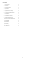
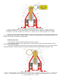
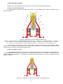
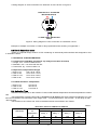
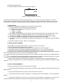
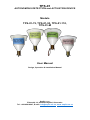
TPS-01 AUTONOMOUS DETECTION and ACTIVATION DEVICE Models TPS-01-72, TPS-01-93, TPS-01-110, TPS-01-M User Manual Design, Operation & Installation Manual Sapfir s.r.o. Záhradná 19, 90024 Veľký Biel, Slovensko Tel.: +42145916247, E-mail: [email protected], www. sapfir-sro.eu CONTENTS 1. Introduction 3 2. General 3 3. Product Range 3 4. Operation 3 5. Application & Design 5 6. Technical Characteristics 6 7. Limitations 7 8. Installation & Wiring 8 9. Safety Requirements 8 10. Service Life & Maintenance 8 11. Packaging 9 12. Disclaimer 9 13. Warranty 9 14. Appendix 1 9 2 1. INTRODUCTION This document represents a user manual and provides technical information on design, operation and maintenance of TPS devices. It also includes warranty. 2. GENERAL TPS is a unique autonomous thermal activation and detection device that allows detecting a fire and activating a powder, aerosol or gaseous fire suppression system. Also the device has features such as provision of a signal to a fire panel and incorporation of an additional output designed to shut down the electrical equipment or activate an alarm (depends on a specific modification). TPS can also be used as a thermal detector with a fixed temperature reading and can be connected to an existing fire detection circuit or a fire-indicating panel. TPS-01PV is a special design version of TPS-01 containing an intrinsically safe interface and designed for use in hazardous areas. TPS-01 is unit capable of working 12 years without any technical service from the operator. 3. PRODUCT RANGE The TPS comes in four different models. Three models operate automatically, similar to the thermal detectors with rated temperatures. The fourth model is designed for manual operation. The models are as follows: 1. Model TPS-01-72 (suitable for cold areas). 2. Model TPS-01-93 (suitable for motor rooms and tracks). 3. Model TPS110 (suitable for motor rooms and tracks). 4. Model TPSM (manual operation). All models could be accomplished in all design versions - for use in harsh environments, in detection circuit or/and in hazardous areas. 4. OPERATION 4.1 General No external power supply is required for operation of the TPS device. TPS device comes in two basic types, for automatic and manual operation. 4.2 Automatic Operation A schematic of TPS for automatic operation is shown in Figure 1. The main feature of the automatically operated TPS is a special heat-sensitive element 7 with a rated temperature reading. When subjected to a fire or a heat the element expands at the rated temperature reading and releases a spring-loaded rod 10 mounted inside a nosepiece 9. 3 Figure 1. Schematic of TPS-01 (automatic operation) 1 - base, 2 - electric terminals, 3 - RF & EMI shielded protective cover, 4 - magnet, 5 - housing made from a high-temperature plastic, 6 - compression spring, 7 - heat sensitive element made from a shape memory alloy, 8 - safety pin, 9 - bronze nose piece, 10 - bronze rod, 11 - frame of reel, 12 - electromagnetic coil, 13 – diode. The spring moves a cylindrical shape magnet 4, which is mounted on the rod 10, through an induction coil 12. The induction coil generates an electric impulse. The impulse is transmitted to the electrical terminals 2 and further to the aerosol or powder fire extinguishers. 4.3 Manual Operation A schematic of TPSM for manual operation is shown in Figure 2. In the manually operated TPS a special ring 5 is used instead of the heat-sensitive element used in automatically operated models. In case of fire a split pin 6 is removed from the device by manually pulling the ring 5. This action releases a spring-loaded pin 9. Further sequence of events is identical to that for automatically operated T-start. Figure 2. Schematic of TPS-01-M (manual operation) 1 - base, 2 - electric terminals, 3 - RF & EMI shielded protective cover, 4 - magnet, 5 - pull ring, 6 - split pin, 7 - bronze nose piece, 8 - compression spring, 9 - bronze rod, 10 - housing made from a high-temperature plastic, 11 - frame of reel, 12 - electromagnetic coil, 13 – diode. 4 5. APPLICATION & DESIGN Depending on the intended use TPS-01 device comes in three various design versions. 5.1 Use in harsh environments For applications in harsh environments the TPS-01 can be installed with a special protective cup as shown in Figure 3. Figure 3. Schematic of TPS-01 with a protective cup 1 - base, 2 - electric terminals, 3 - RF & EMI shielded protective cover, 4 - magnet, 5 - compression spring,6 - bronze rod, 7 - bronze nose piece, 8 - heat sensitive element made from a shape memory alloy, 9 - protective cup, 10 - "O" Ring, 11 - bushing, 12 - housing made from a high-temperature plastic, 13 - frame of reel, 14 - electromagnetic coil. The protective cup shields the TPS-01 device from possible mechanical and environmental impacts, however, the cup reduces the sensitivity of the heat-sensitive element in the automatically operated TPS-01 devices and as a result increases their activation time. 5.2 Use in detection circuit In most applications apart from its use as an activation device TPS-01 is also used as a thermal detector. In such applications the device is connected to an existing fire detection line or directly to a fire panel via a specially designed junction box. A schematic of TPS-01 with such junction box for use in detection circuit is shown in Figure 4. Figure 4. A schematic of TPS with a detection circuit junction box. 5 A wiring diagram of TPS connection to a detection circuit is shown in Figure 5. ELEKTRCALLY ACTIVATED INITIATOR DEVICE 1 2 R TO FIRE PANEL DETECTION CIRCIT Figure 5. Wiring diagram of TPS connection to a detection circuit. Example of multiple connection of TPS for large protected areas showing on Appendix 1. 5.3 Use in hazardous areas TPSPV is a special design version of TPS containing an intrinsically safe interface and designed for use in hazardous areas. 6. TECHNICAL CHARACTERISTICS 6.1. Dimensions and Mass (protective cup and junction box excluded) 1. Length, mm - not more than 85 mm; 2. Diameter, mm - not more than 65 mm; 3. Total mass, kg - not more than 0.2 6.2 Operation Temperature Ranges 1. TPS-01-72 from -60 to +55°C; 2. TPS-01-93 from -60 to +75°C; 3. TPS-01-110 from -60 to +95°C; 4. TPS-01-M from -60 to +95°C 6.2 Rated Activation Temperature 1. TPS-01-72 2. TPS-01-93 3. TPS-01-110 +72°C±5°C +93°C±5°C +110°C±5°C 6.4. Activation Time Activation time depends on the model of T-start, initial ambient temperature and the temperature increase rate. The temperature increase rates (TIR) of 3°C/min and 30°C/min have been selected as standard. For TIR 30°C/min activation time should be in the range of 58 - 144 seconds and for TIR 3°C/min - in the range of 580 -960 seconds. Test results on the TPS72 and TPS110 activation times are showed in the Table 1. Table 1. TPS Model TPS72 TPS-01-93 TPS110 Activation times for TPS72 and TPS110 TIR 30°C/min TIR 3°C/min Initial ambient air Max time Min time Max time Min time temperature, delay, s delay, s delay, s delay, s °C 35 93 85 740 724 55 70 114 137 98 125 6 820 950 808 937 6.5 Electrical parameters An electrical diagram of the device is showed in Figure 6. Output Figure 6. Electrical diagram for TPS. The device generates an electric impulse with amplitude of 3.5 V DC at the circuit resistance of 1.0 Ohm. The duration of the electric impulse is not less than 1 millisecond for the amplitude of not less than 3.0 V DC. The device can activate the following types of electrical initiators: MB-2H, 3A-1, PP-9, YGP-10, and similar. 7. LIMITATIONS The design and application limitations for TPS devices are as follows. 1. Volume protected by one device shall not exceed 18 m3. 2. The dimensions of a protected area shall not exceed: Height - 3.0 meters Width - 2.4 meters Length - 2.5 meters 3. The device should be located in the middle of the protected area at 100-150 mm below the ceiling. 4. The device is capable of sustaining vibration from 0.5 to 200 Hertz with acceleration of 4g. 5. The device is capable of sustaining impacts of up to 4g-force of 2 to 50 milliseconds duration. 6. The device is suitable for application in hazardous areas of 2ExeIIT6 category. 7. The TPSPV device is an intrinsically safe device and suitable for use in hazardous areas of POExial category. 8. Maximum relative humidity - 98% (no condensation). 8. INSTALLATION & WIRING The installation and wiring requirements for TPS-01 devices are as follows. 1. One circuit shall have not more than 10 devices. 2. The length of the cable between two devices in a loop shall not exceed 3 meters. 3. The devices shall be connected in parallel. Normal polarity of "+" to "+" shall be observed. 4. The device can be used in high density electromagnetic and high frequency energy zones. 5. Activation cables shall be fire-resistant with copper conductors. A cross-section area of each conductor should not be less than 1 mm2 or 0.5 mm2 for a multiple core cable. 6. If run through a high frequency energy zone, such as a two-way radio, a sonar etc, the cable should be screened. 7. If run through the electric magnetic fields of high density, such as high voltage transformers in power substations or cable tunnels, the cable should be enclosed in a steel conduit. 8. Cable screen and steel conduit shall be grounded in accordance with the standard requirements. 9. If there is a likelihood of any mechanical damage, the cable should be enclosed into a plastic or metal conduit. 9. SAFETY REQUIREMENTS The safety requirements for the TPS device are as follows. 1. The device shall be installed and maintained in accordance with its design requirements and technical specifications. 2. Only authorized personnel can install, re-set and service the device. 3. The device shall only be used as intended - for detection of fire and activation of a fire suppression system. 4. The attached safety pin shall be in its place during any installation, maintenance or service work conducted within the protected area to prevent an accidental discharge of the fire suppression system. 7 5. The heat-sensitive element shall be firmly fixed in its position in the device. 6. All screws on electrical terminals shall have spring washers. 7. In case TPS does not incorporate the junction box for use in the detection circuit it should be attached to another appropriate junction box to ensure proper cable connections. 8. The device is incapable of generating the electric impulses at levels dangerous for humans or animals. 9. The connecting of the cable to the fire suppression units shall always be the last wiring procedure. 10. After the system has been commissioned remove the safety pin (if required a protective copper cup could be installed after removal of the safety pin) to ensure the system is left in operable condition. Before removing the pin ensure the heat- sensitive element is firmly attached to the bronze rod inside the device. 11. Where the protective copper cup is installed bend the edge of the cup into the bushing in two opposite points in order to avoid its accidental removal. 12. Hot work must not be carried out within the vicinity of any TPS-01 device as naked flame or exposure to high temperatures may cause activation of the device and the incorporated fire suppression system. If so the fire suppression system shall be disconnected and the device removed prior to any hot work being carried out. 10. SERVICE LIFE & MAINTENANCE 1. The TPS device is maintenance free. The reliability of the device is not less than 50,000 hours under normal ambient conditions. The service life of the device is 10 years. 2. f damaged or exposed to the fire the device shall not be re-used. 3. Should the heat-sensitive element be damaged, the device shall not be used. 4. Should the device be set off by an accident it shall be returned back to the supplier or the manufacturer. It shall not be re-used as the heat-sensitive element might have been damaged or overheated. 11. PACKAGING 1. The devices are placed in a cardboard box. There are 10 devices per box. 2. Inside the box the devices are placed in rows with a carton packaging material filling the space between the devices. 3. A packaging list, a user guide and manual are enclosed in a plastic envelope and placed onto the top row (one envelope per every ten devices). 4. The following labels shall be attached to each cardboard box: Fragile Keep in dry place Do not drop Delicate equipment 12. DISCLAIMER This manual is for use by trained and authorized personnel only. The document is accurate at time of issue, however, is subject to changes to its content from time to time. 13. WARRANTY The manufacture claims that TPS-01 have undergone a quality control and have no defects. Warranty applies for two years from the date of purchase. This limited warranty does not cover any TPS-01 device that has been damaged or rendered defective as a result of an accident, misuse or abuse, or serviced by anyone other than authorized service person, or by using the parts that are not manufactured or sold specifically for this device, or any modification done without written permission of the manufacturer. 8 Appendix 1 Multiple connection of TPS-01 with Junctions boxes showing on schematic diagram below. In case of axillaries equipment to be shut down simultaneously with activation of extinguishing system one out of two schematic to be chosen. For normally open contacts parallel connection is in use. For normally close contacts connection in series should be chosen (see diagrams below). Up to 10 the TPS-01 may be connected to one loop To fire modules 1 2 1 1 2 2 To fire indication panel R 9