1
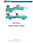
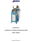
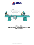
PHOENIX-02 FH (DK 540)
FOUR HEAD PVC (VINYL) WELDING MACHINE
USER’S MANUAL
1
Operating and Safety Instructions
CONTENTS
1. General information
1.1. Introduction
1.2. Distributor
2. Machine’s description and purpose of use
2.1. Machine’s definition
2.2. Technical features
2.3. Dimensions
2.4. General views
3. Safety
3.1. Safety information
3.2. Accident prevention
3.3. General safety information
4. Transport of the Machine
5. Installation of the Machine
6. Machine Safety Information
7. Operation
7.1. General
7.2. Welding operation
7.3. Working with cooling unit (SA 250)
8. Maintenance, Service and Repair
8.1. Starting to Work
8.2. Air Pressure Adjustments
8.3. Cleaning and Replacement of the Teflon
8.4. Lubrication
8.5. Maintenance at the End of Working Day
9. Troubleshooting Guide
2
1. GENERAL INFORMATION
1.1. INTRODUCTION
The user’s manual contains necessary information about the machine parts. Each machine
operator should read these instructions carefully, and the machine should be operated after fully
understanding them.
Safe and efficient use of the machine for long term depends on understanding and following the
instructions contained in this manual.The technical drawings and details contained in this manual
constitute a guide for the operator.
1.2 DISTRIBUTOR
ATech Machine, Inc.
12108 Conway Road – Beltsville, MD 20705 - USA
Phone: +1-240-264-1118 Fax: +1-301-560-6627
Website: www.ATechMachinery.com
E-mail: [email protected]
In case of any technical problem please contact your nearest ATECH dealer, or ATECH
head office through the above mentioned phone, fax or e-mail address.
Technical labels with the model description of the machine are fixed onto the front side of
each machine.
The machine’s serial number and manufacturing year are stipulated on the technical label.
2. MACHINE’S DESCRIPTION AND PURPOSE OF USE
2.1 MACHINE’S DESCRIPTION
Four head corner welding machine for PVC profiles.
2.2 TECHNICAL FEATURES
PLC control system with touch screen display
Automatic adjustment of weld limitation thickness between 0.2 and 2 mm
Profile welding angle is 90°
Automatic unloading after welding
Safety protective barrier
Capacity to create & save to memory data on 200 profiles
Six language versions
Machine complies with CE, UL, CSA Safety Directives
STANDARD ACCESSORIES
Lubrication pump
13 mm wrench
OPTIONAL ACCESSORIES
SA 250 Cooling unit
TEKNİK ÖZELLİKLER
TECHNICAL FEATURES
h
b
DK 540
8.4 kW 50 Hz
400 V AC N PE
h=140 mm max.
h= 30 mm min.
b=130 mm max.
3
H
0.2-2mm
h
BAR
Hava Tük
Air Const
L
W
Kg
cm
b
h=2700 mm max.
h= 400 mm min.
55 Lt/dak
408x220x175 1690 2079
b= 3100 mm max. 6-8 Bar
Lt/Min
b= 400 mm min.
2.3 DIMENSIONS
5150 MM
(203”)
HEIGHT :
1500 MM
(59”)
FIGURE 1
4
4500 MM
(177”)
2.4 GENERAL VIEWS
Control
panel
Barrier
Working
area
Transfer
conveyor
Barrier
FIGURE 2
Control panel
Barcode
reader
Emergency
stop button
System
start button
FIGURE 3
5
3. SAFETY
3.1 SAFETY INFORMATION
The symbols shown hereunder are necessary to be read with special attention.
Not reading or observing of them may cause damage to the equipment or personal injury.
IMPORTANT
The IMPORTANT symbol above is one telling to apply special care and to be careful at carrying
out the specified operation
CAUTION !
The CAUTION! Symbol above warns you against specific dangers, and requires to read the text.
Not observing may cause damage to the equipment.
DANGER WARNING
The above symbol DANGER WARNING, warns you against specific dangers, and you have
definitely to read them. Negligence may cause damage to the equipment and bodily injury.
Read the user’s manual carefully before using the machine or carrying out maintenance
works.
3.2. ACCIDENT PREVENTION
3.2.1 Our machines are manufactured in accordance with EN 60204-1 and EN 292-2 CE safety
directives, which cover national and international safety directives.
3.2.2 It is the task of the employer to warn his staff against accident risks, to train them on
prevention of accidents, to provide for necessary safety equipment and devices for the operator’s
safety.
3.2.3. Before starting to work with the machine, the operator should check the features of the
machine, learn all details of the machine's operation.
3.2.4. Machine should be operated only by staff members, who have read and understood the
contents of this manual.
3.2.5. All directives, recommendations and general safety rules contained in this manual have to
be observed fully. The machine cannot be operated in any way for purposes other than those
described herein.Otherwise, the manufacturer shall not be deemed responsible for any damages
or injuries. And such circumstances would lead to the termination of the warranty.
6
3.3 GENERAL SAFETY INFORMATION
3.3.1. The power cable should be led in such a way that nobody can step on it or nothing can
be placed on it. Special care has to be taken regarding the inlet and outlet sockets.
3.3.2. If the power cable should be damaged during operation, don't touch and unplug it. Never
use damaged power cables.
3.3.3. Don’t overload machines for drilling and cutting. Your machine will operate more safely
with power supply in accordance with the stipulated values.
3.3.4. Don’t place your hands between parts in motion.
3.3.5. Use protective eye glasses and ear plugs. Don't wear oversize clothes and jewels.
These can be caught by moving parts.
3.3.6. Keep your working place always clean, dry and tidy for accident prevention and safe
operation.
3.3.7. Use correct illumination for the safety of the operator. ( ISO 8995-89 Standard The
lighting of indoor work system )
3.3.8. Don't leave anything on the machine.
3.3.9. Don’t use any materials other than those recommended by the manufacturer for cutting
operations on the machine.
3.3.10. Ensure that the work piece is clamped appropriately by the machine's clamp or vice.
3.3.11. Ensure safe working position, always keep your balance.
3.3.12. Keep your machine always clean for safe operation. Follow the instructions at
maintenance and replacement of accessories. Check the plug and cable regularly. If damaged,
let it replace by a qualified electrician. Keep handles and grips free of any oil and grease.
3.3.13. Unplug first, before conducting and maintenance works.
3.3.14. Ensure that any keys or adjustment tools have been removed before operating the
machine.
3.3.15. If you are required to operate the machine outside, use only appropriate extension
cables.
7
3.3.16. Repairs should be carried out by qualified technicians only. Otherwise, accidents may
occur.
3.3.17. Before starting a new operation, check the appropriate function of protective devices and
tools, ensure that they work properly. All conditions have to be fulfilled in order to ensure proper
operation of your machine. Damaged protective parts and equipment have to be replaced or
repaired properly (by the manufacturer or dealer).
3.3.18. Don’t use machines with improper functioning buttons and switches.
3.3.19. Don’t keep flammable, combustive liquids and materials next to the machine and electric
connections.
IMPORTANT
4. TRANSPORT OF THE MACHINE
* The transport should be done by qualified personnel only.
4.1. The machine should be transported by lifting with proper equipment (not touching the
ground during the transport).
4.2. The Machine is delivered wrapped in nylon as packaging, unless other form of packing is
agreed upon with the customer.
4.3. For the weight and overall dimensions of the machine see Page 22
5. INSTALLATION OF THE MACHINE
Machine installation will be made by company’s or our representative’s technical service.
Necessary air and electrical facilities should be organized by the customer.
6. MACHINE SAFETY INFORMATION
6.1 Your machine operates with 3-Phase 220V 60Hz. Let the electric installation of your machine
carry out by a qualified electrician only.
6.2 Lifting, installation, electric, pneumatic maintenance of the machine should be carried out by
qualified personnel only.
6.3 Routine maintenance and scheduled maintenance should be carried out by qualified
personnel after unplugging the machine and disconnecting the air supply first.
6.4 Ensure that the machine has been cleaned, tested and maintained before starting to operate.
6.5 Check the safety devices, power cable and moving parts regularly.Don’t operate the
machine before having replaced defective safety devices or faulty parts.
6.6 Keep foreign materials away from the working area of the machine, keep away from the
machine’s moving parts
IMPORTANT
The safety data have been defined above. In order to prevent physical damage or damage
to the equipment, please read the safety information carefully and keep the manual
always in an easy accessible place.
8
7. OPERATION
7.1 GENERAL
PHOENIX-02 FH (DK 540) PVC Corner Welding was designed only to weld and join profile
corners and can not be use for the different purposes.
7.2 WELDING OPERATION
PHOENIX-02 FH (DK 540) Welding machine completes welding process cycle automatically. All
settings and processes are held through control panel. After operator has placed profiles to be
welded the machine finishes welding process automatically.
HOME PAGE
Figure 101
When energy is provided to the machine, this page appears. After opening, the page reference
should be established by pressing on start button. By clicking on language selection button, the page, in
which languages are selected, is opened. With manual buttons button, manual page, in which the heads
are moved manually, is reached. However, if the manual page was opened, this page should be closed
down and machine should be sent to reference.
LANGUAGE SELECTION PAGE
Figure 102
9
:
When this icon is selected, pressing the OK button will activate the Turkish
language. After that, every time you boot the machine, program runs in Turkish.
:
When this icon is selected, pressing the OK button will activate the English
language. After that, every time you boot the machine, program runs in English.
:
When this icon is selected, pressing the OK button will activate the Russian
language. After that, every time you boot the machine, program runs in Russian.
:
When this icon is selected, pressing the OK button will activate the French
language. After that, every time you boot the machine, program runs in French.
:
When this icon is selected, pressing the OK button will activate the Spanish
language. After that, every time you boot the machine, program runs in Spanish.
:
When this icon is selected, pressing the OK button will activate the Arabic
language. After that, every time you boot the machine, program runs in Arabic.
OPERATION BY SCANNING THE BARCODE
Figure 103
The page in the figure is for operations with barcode
By pressing this button, the heating process of heaters (irons) is started. Before the
desired temperature is reached, machine does not weld. If welding process is forced to start before reaching to
desired temperature, machine gives “Machine is waiting for heating up” warning message.
10
Figure 104
The temperature of each heads’ heater can be
monitored under the head number in the screen. In
addition the condition of profile whether it is colorful or
colorless, is displayed on the screen.
When this button is hit, heaters are turned off. The temperature of the heaters will
start to decrease after a while.
After temperature is reached to desired values, barcode tag is read by barcode scanner.
Following to reading of barcode, if profile is read for the first time, registration page will appear (see
Figure 106).
Figure 106
In this registration page, after entering the information related with profile, profile is saved to
machine by pressing save button.
Figure 107
By pressing on this button, heating degree, heating time, boiling time, etc.
information related with profile can be reached.
Profile frame dimensions of scanned barcode in x and y- axes appear on the screen (see Figure
108).
Figure 108
Stock code and name of scanned barcode is also seen on the window in which their names are
mentioned (see Figure 109).
Figure 109
11
After dimensions are appeared on the screen, if start button is pressed, heads move to proper
position to place the profiles on the machine. While machine is positioning itself, yellow lamp on panel is
turned on. As long as yellow lamp lights, it should not be entered between the light barriers.
After machine is positioned, profiles are placed. In the meantime, green lamp is switched on.
While green lamp is lighting, it is allowed to enter between light barriers.
After placing the profiles, start button on the machine is pressed and machine comes onto frame
dimension. Green lamp is still lighting and last checks of profile can be performed. Procedures, that
should be followed, are appeared as scrolling text in order on the screen.
With last start, welding process is begun. After this last start, yellow lamp is again turned on.
From now on, it should not be entered between light barriers until welding process is finished up. After
welding process is completed, green lamp is switched on and in order to weld new profile, process can
be started by scanning the barcode again.
Figure 110
If this button is pressed, welding process will be canceled. Operation is terminated
at the moment when this button is pushed.
OPERATION WITHOUT BARCODE
Figure 111
The page seen in the figure is for operations without barcode (see Figure 111).
Unlike the case with barcode, in operations with barcode, the position, where machine moves to,
is provided by manually entering the dimensions from keyboard. To do this,
Figure 112
The window of the axis, to which the value is assigned, is pressed and keyboard appears (see Figure
113).
12
Figure 113
In the pop up window, desired value is entered, accepted
and then window will automatically close. The minimum and the
maximum values of the axis, which is chosen, can be seen on pop
up number window.
Afterwards, welding process is started by pressing on start. The rest of operation is same as the
operations with barcode.
Figure 115
[PARAMETERS] By pressing on this button, the page in
which welding parameters will be changed is opened (see Figure 116).
Figure 116
In the pop up window, all the welding
parameters can be changed. Number keyboard is
displayed by pressing the window whose parameter
will be changed. The desired value is entered from
keyboard and keyboard automatically closes after
acceptance.
Figure 117
While the button is at this position, heads in y- axis move to their place with start
command, in each dimension that is entered. If the size of profiles in y- axis is larger, it will be quite
difficult for operator to place the profiles on the machine. In order to eliminate this situation, the button,
shown in figure, is pressed and the button turns into green color (see Figure 118).
Figure 118
While the button is at this position, machine comes to minimum value in y- axis and
moves to entered dimension in x- axis when dimensions are entered for the profiles larger than 1000
mm and start is given. By giving start after placing the profile of x- axis, machine moves to y value.
Figure 119
13
While the button is at this position, it means that colorless profile will be welded. When
the button is pressed, the button will be in red color (see Figure 120).
Figure 120
If the button is at this position, colorful profile welding is chosen (0.2 mm welding).
Figure 121
If the button is at this position, machine accepts and evaluates dimensions in mm. It
moves to positions in mm.
Figure 122
If the button is at this position, machine accepts and evaluates dimensions in inch. It
moves to positions in inches.
Figure 123
By pressing on this button, the page in which saved guidelines can be displayed or made
choice among them is opened (see Figure 124).
Figure 124
Figure 125
If this button is pressed, likewise operation with barcode, welding in process will be
canceled. Operation is terminated at the moment when this button is pushed.
14
GUIDELINE PROCESSES
Figure 126
This is the page in which processes related with guideline is performed. Here new guidelines can
be created and, changes can be made on saved profile information. Here, keyboard is displayed by
pressing on the window in which the value is aimed to change or new registration is performed. After
entering the required information from pop up keyboard, it is approved and keyboard is automatically
closed.
Figure 127
[Change] If this button is pressed, changes can be made on saved guideline. Performed
action is saved on selected guideline.
Figure 128
[Create guideline] If any value is entered and then this button is pressed, it is registered
as a new guideline.
When the button named colorful is pressed, profile is selected as colorful and the machine will
work accordingly.
When the button named colorless is pressed, profile is selected as colorless and the machine will
weld according to colorless profile.
Figure 129
[Delete] If this button is pressed, selected profile will be deleted.
Figure 130
If this button is pressed, all saved profile guidelines will be deleted. However, password
should be entered for deleting process. The required password is “1234”.
“+” and “-“buttons are for navigating between guidelines.
MANUAL PAGE
15
Figure 131
The page shown above is the screen in which units can be moved manually. Here, the unit whose
button is pressed manually operates and in the next click, unit turns off.
With direction buttons, axes can be manually manipulated. Below each axis, there are slow and
fast motion options. In each press to button, it changes as slow or fast. Right above the buttons, the
position where heads are located can be seen.
Figure 132
[BAND ENGINE] If the band engine button is pressed, engines of welding machine and
cooling station will be manually turned on.
Figure 133
[NOT ALLOWED] When not allowed button is pressed, it is turned into allowed and it
allows entering between light barriers while some commands are operating.
Figure 134
[SET BARRIER] With set barrier button, air pressure is activated and when the button is
pressed, it is set. From now on barrier is in active state.
Figure 135
[UNIT SETTINGS] When this button is pressed, the page in which speed of units’ pistons
is opened (see Figure 136).
16
UNIT SETTINGS PAGE
Figure 136
Above is the page in which unit speeds are set. The unit, of which button is pressed, is turned on
and off within the duration written next to it. In the meantime, the speed of pistons is manually adjusted.
Light, which is next to active unit, blinks. Values written next to units are speed values at factory outlet.
The functions of not allowed and set barrier buttons are same as the functions described in
manual page.
Figure 137
If this button is pressed, the page, in which on and off positions of input and output can be
seen, is opened.
Figure 138
It is the page in which previous alarms can
be seen. At the same time, alarm time can be seen
(see Figure 138).
17
Figure 139
This is calibration selection page. By using
this page, operator or service personnel reach the
screen, in which adjustment is made.
With language selection button, the page, in
which the current language will be changed, is
reached.
With return to factory settings button,
machine returns to factory settings.
Figure 140
[NO COOLING STATION] If there is not a cooling station on the line, the position
of button should be in this way. When the button is pressed, button turns into green color (see Figure
141).
Figure 141
[COOLING STATION EXISTS] While the button is this position, this means that
there is cooling station on the line and during welding cycle, machine proceeds according to that.
Figure 142
[OPERATOR] If this button is pressed, the page which is needed by operator to
make calibration adjustments is opened. However, entrance to page is encrypted. The required
password is “1234”.
Figure 143
[SERVICE] When this button is pressed, the page in which service personnel will make
calibration adjustments is opened. Entrance to this page is encrypted.
18
OPERATOR CALIBRATION PAGE
Figure 144
It is the page in which operator will make calibration adjustments. If there is any error in welding
machine, machine is adjusted from this page. Values in the window, on which position is written, display
the position of heads. Values in window on which offset is written are machine calibration values.
Adjustments are made by changing these values. Adjustments are made as following:
For instance, consider that the profile, which is cut as 500 mm in exact size, is clenched in xaxis. If this profile has 1 mm free space on the machine (if the machine opens up more), value on x
offset window will be entered 1 mm more and then accepted. If the profile does not fit to table after it is
placed on machine (if the machine opens up less), value in offset is entered 1 mm less. Afterwards
is pressed and machine reference is canceled. Finally, by pressing on start button machine
is moved to reference. After the machine is completed to take reference, newly entered offset values will
be valid. Same procedure is also valid for settings of other axes.
SERVICE CALIBRATION PAGE
Figure 145
Unlike operator calibration page, there are some adjustments. These are as following:
Figure 146
[WELDING QUOTA] In this window, the amount which will be melted during
welding is written. Weld melting value of machine is 6.5 mm at factory outlet.
19
Figure 147
[PROFILE PLACEMENT ALLOWANCE] It is the value at which amount machine
is expanded more from the written profile dimension in order to locate the profiles on to the machine
table easily. This value is 100 mm at factory outlet.
Figure 148
[PROFILE REMOVAL ALLOWANCE IN X- AXIS] It is the value at which amount
machine is expanded in x-axis from current location to leave the profile onto conveyor after welding
process is completed. This value is 310 mm at factory outlet.
Figure 149
[SAVING BURR] After the welding process is completed, machine first lifts up
the profile so x-axis is a little bit cleared. This is because of removing the profile without getting welding
burrs caught in anywhere. This value is 50 mm at factory outlet.
After making adjustments in this page, machine reference is canceled by pushing
button. Finally, machine is addressed to reference again by hitting start button and process is
completed.
20
7.3 WORKING WITH COOLING UNIT (SA 250)
Cooling unit (SA 250) is not standard equipment delivered together with the machine. It
can be supplied from our company optionally.
Cooling Unit (SA 250) is a supplementary unit for transferring the frame whose welding process
at Welding Machine (DK 540) is finished, to Corner Cleaning Machine (CNC 610). Frame, whose
process is finished at Welding Machine, is transferred to Cooling Unit via transfer conveyors.
Cooling Unit brings the frame to a point where Profile Rotating Robot will take. With the aid
profile rotation robot the burrs of the frame are cleaned thus the cycle is completed.
When Cooling Unit is used only with welding machine it facilitates welding and saves time.
Thanks to transfer conveyors frame, whose welding process has finished, is put on Cooling Unit.
The operator, without pausing the cycle, can continue to welding process.
FIGURE 4
21
8. MAINTENANCE and CLEANING
8.1. STARTING TO WORK
8.1.1 Ensure that the table and all parts are clean and dry. Degrease the table and dry it.
8.1.2 Clean the machine surface.
8.1.3 Check the pressure of the air pressure system.
8.1.4 Check the air pressure filter and the oil level of the conditioner. Fill up oil, if necessary.
(FIGURE 5)
8.2. AIR PRESSURE ADJUSTMENT
8.2.1 Pull the adjustment button of the conditioner upwards.
8.2.2 Turning the adjustment button in clockwise direction increases the pressure.
8.2.3 Turning the adjustment button in counter clockwise direction decreases the pressure
8.2.4 Once you read 6-8 Bar on the manometer, push the adjustment button of the
conditioner down and lock it in that position.
8.2.5 The manufacturer recommends to use the following oils with the conditioner: TELLLUS
C 10 / BP ENERGOL HLP 10/ MOBIL DTE LIGHT / PETROL OFISI SPINDURA
8.2.6 Make the adjustment of oil unit level so that for 10 work cycle 1 droplet is sent to the
system.
FIGURE 5
22
8.3. CLEANING AND REPLACEMENT OF THE TEFLON
8.3.1. Disconnect the electric and pneumatic supply.
8.3.2. Use a clean cloth to clean the Teflon.
8.3.3. When Teflon is worn or got older loosen the nuts under the wooden arms with a key.
Rotate the arms counter clockwise and rewind the old Teflon. When you rotate the arms
new Teflon will be unwinded from the roll. After adjusting the tightness of Teflon tighten the
nuts again.
FIGURE 6
8.4. LUBRICATION
8.4.1. Disconnect the electric and pneumatic supply.
8.4.2. Remove the lubrication system cap.
8.4.3. Using grease pump supplied together with the machine, lubricate as in Figure 9.
8.4.4. To lubricate bottom ways and housings, change the apparatus fitted to the head of
grease pump. (FIGURE 10)
8.4.5. Perform lubrication process regularly on every week.
23
Remove cap
FIGURE 7
FIGURE 8
FIGURE 10
FIGURE 9
8.5. MAINTANENCE AT THE END OF WORKING DAY
8.5.1 Disconnect the electric and pneumatic supply.
8.5.2 Clean the machine surface and remove all foreign materials.
8.5.3 After cleaning the table, dry it with a cloth (don’t use aggressive substances for
cleaning, which could damage the paint).
Unplug and disconnect the air pressure connections first, before carrying out these
works.
24
9. TROUBLESHOOTING GUIDE
Here are some recommendations for solving urgent problems. If the trouble cannot be solved, or
if you have a problem other than those described hereunder, please contact our technical
service or your nearest dealer.
.
TROUBLES
CAUSES
REMEDY
The resistance does not No power supply to the Check the fuse, plug and socket.
heat
machine
Connect the thermocouple wire.
The thermocouple does not
work
Check
the
temperature
display
adjustment (245˚)
The temperature display
needs to be set.
The clamps do not work.
The air pressure is too low. Check the air hose connections of the
machine.
The guide plate does not
move.
Adjust the air pressure at the conditioner
The heating plate does not
move.
Machine does not weld or The profiles were cut in Check the angles of the profile ends.
different angles.
The saw blade might need to be
the welding is not clean.
sharpened.
The Teflon is dirty or torn.
The Teflon should be cleaned
replaced.
If these recommendations do not solve the trouble, please ask for technical service.
25
or