1
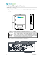
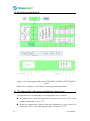
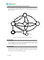
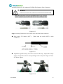
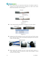
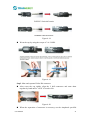
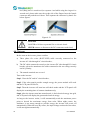
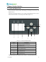
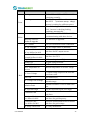
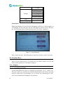
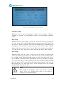
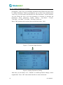
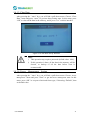
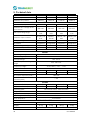
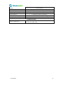
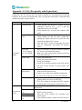
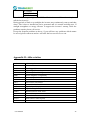
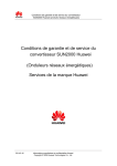
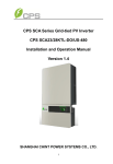
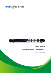
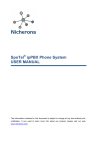
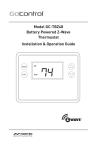
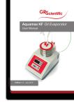
User Manual TRI010KTL/TRI012KTL/TRI017KTL/TRI020KTL Contents Copyright Declaration ............................................................................................................... 3 1. Introduction ........................................................................................................................... 4 1.1. Introduction .................................................................................................................... 4 1.2. How to Use this manual ................................................................................................. 4 1.3. Applied Designations (Warning, Caution, Note) ........................................................... 4 1.4. Important Safety Information ......................................................................................... 4 1.5. General Safety Rules for Working on Electrical Equipment.......................................... 6 1.6. System Sizing ................................................................................................................. 7 2. Technical Description of Inverters ........................................................................................ 8 2.1. Mechanical design .......................................................................................................... 8 2.2. Electrical system design ............................................................................................... 10 2.3. The illustration of derating and limit the input power .................................................. 10 3. Operation mode illustration of the inverter ......................................................................... 11 3.1. Wait mode .................................................................................................................... 11 3.2. Check mode .................................................................................................................. 11 3.3. Normal mode ................................................................................................................ 12 3.4. Fault mode .................................................................................................................... 12 3.5. Flash mode ................................................................................................................... 12 3.6. Shut down ..................................................................................................................... 12 4. Installation and startup ........................................................................................................ 13 4.1. Installation precaution .................................................................................................. 13 4.2. Install steps ................................................................................................................... 14 4.3. Electrical connection .................................................................................................... 16 4.3.1. Connection to the grid (AC output) ....................................................................... 16 4.3.2. Connection to PV generator (DC input) ................................................................ 18 4.4. Test run ......................................................................................................................... 22 5. Human Machine Interface ................................................................................................... 23 5.1. Control and Display Panel ............................................................................................ 23 5.2. LED Display ................................................................................................................. 24 User Manual 1 5.3. LCD Display................................................................................................................. 26 5.4. Function Keys............................................................................................................... 28 5.4.1. Configure ............................................................................................................... 28 5.4.2. Energy yield........................................................................................................ 33 5.4.3. Inverter state .......................................................................................................... 33 5.4.4. Device Information................................................................................................ 34 5.4.5. log Information ...................................................................................................... 34 5.5. Display of Fault ............................................................................................................ 35 6. Communication and Monitoring ......................................................................................... 36 6.1. Communication Interfaces............................................................................................ 36 6.2. Communication ............................................................................................................ 36 6.2.1. RS-232 Communication for Three inverter type ................................................... 36 6.2.2. RS-485 Communication for Several inverters....................................................... 37 6.2.3. Wireless ................................................................................................................. 38 6.2.4. USB ....................................................................................................................... 38 6.3. Monitoring .................................................................................................................... 38 7. Maintenance and Repair ...................................................................................................... 39 7.1 Routine maintenance ..................................................................................................... 39 7.2 Notes of maintain or service .......................................................................................... 39 7.3 Safety for maintain or service........................................................................................ 39 8. Technical data...................................................................................................................... 40 9. Quality assurances ............................................................................................................... 42 10. Contact Information........................................................................................................... 43 Appendix A: FAQ (Frequently asked questions) .................................................................... 44 Appendix B: Abbreviation ...................................................................................................... 45 2 User Manual Copyright Declaration The copyright of this manual belongs to Trannergy Co., Ltd.. Any corporation or individual should not plagiarize, partially copy or fully copy it (including software, etc.), and no reproduction or distribution of it in any form or by any means. All rights reserved. Trannergy reserves the right of final interpretation. This manual is subject to change according to user’s or customer’s feedback. Please check latest version at: http://www.trannergy.com. User Manual 3 1. Introduction 1.1. Introduction This manual describes Trannergy solar inverters TRI010KTL/ 012KTL/ 017KTL/ 020KTL. These products are among the most technologically advanced and efficient inverters on the market and are designed to ensure a stable power supply for many years. The TRI inverter is a transformerless based inverter. 1.2. How to Use this manual Please read the safety instructions in this manual first. Throughout the manual it is assumed that the reader is familiar with AC and DC installations and knows the rules and regulations for electrical equipment and for connecting it to the utility AC grid. It is especially important to be familiar with the general safety rules for working with electrical equipment. 1.3. Applied Designations (Warning, Caution, Note) Throughout the manual important information is shown at different levels depending on the character of the information, as shown here: Safety information important for human safety. Violation of warnings may result in injury to persons or death. Information important for the protection of property. Violation of this type of information may cause damage and loss of property. Useful additional information or “Tips and Tricks" on specific subjects. 1.4. Important Safety Information Read this before installing, operating or maintaining the inverter. Before installation: Check for damage to inverter and packaging. If you are in doubt, please contact your supplier before installing the inverter. Check 4 User Manual the voltages of the solar modules and make sure they are within the limits of the Trannergy inverter specifications before connecting them to the inverter. Installation: Only trained and authorized personnel familiar with local electrical codes may install the inverter. For optimum safety, please follow the steps described in this manual. Keep in mind that the inverter has two voltage carrying sides, the PV input and the AC grid. Disconnecting the inverter: Always disconnect the AC line first! Afterwards disconnect the PV lines. Note that the inverter can still be charged with very high voltages at hazardous levels even when it is disconnected from grid/mains and solar modules. Wait at least 15 min. before proceeding, after having disconnected from grid and PV panels. operating the inverter: Before connecting the AC grid to the inverter, make sure that the installation cover is mounted again. The inverter must not be open during operation. Maintenance and modification: Only authorized personnel are allowed to repair or modify the inverter. To ensure optimum safety for user and environment, only the original spare parts available from your supplier should be used. Functional safety parameters: Unauthorized changes of functional safety parameters may cause injury or accidents to people or inverter. Additionally it will lead to the cancelling of all inverter operating approval certificates. The Trannergy inverters in the TRI range are all designed according to international safety requirements. If non-original spare parts are used, the compliance with CE guidelines in respect of electrical safety, EMC and machine safety is not guaranteed. User Manual 5 1.5. General Safety Rules for Working on Electrical Equipment All persons installing, maintaining or servicing inverters should be trained in and have experience with the general safety rules to be observed when working on electrical equipment. Installation and service personnel should also be familiar with local requirements, rules and regulations as well as safety requirements. To provide a general guideline for safety precautions, five well-known and widely accepted rules are repeated below. The list should by no means be considered as exhaustive. The person performing work on electrical equipment is responsible for the safety of persons and property! Disconnecting Disconnect all cables supplying voltage to the working place before starting any work. Please note that a lack of voltage is no guarantee that disconnection has been performed. Protecting against reconnection Prevent the system from reconnecting by marking, closing or locking off the work area. Unintentional reconnection may result in severe accidents. Checking that system is voltage free Ascertain conclusively by means of a voltage tester that the system is voltage free. Check all terminals to ensure that the system is voltage free (on each individual conductor). Covering adjacent voltage-carrying components preventing persons from gaining access to them and Cover up all voltage-carrying system components that can harm you while working. Make sure that danger areas are clearly marked. 6 User Manual 1.6. System Sizing When dimensioning a photovoltaic system, it must be ensured that the open circuit voltage of the PV string never exceeds the maximum permissible input voltage of 1000V DC. The PV string open circuit voltage during parallel string operation is 900V. Higher voltages may result in permanent damage to the inverter. The selection of PV string output should be based on the optimum utilization of the invested capital compared to the expected annual energy yield from the system. This optimization depends on local weather conditions and should be considered in each individual case. The inverter incorporates an input power limiting device, which automatically keeps the power at levels that are safe for the inverter. The limitation depends mainly on internal and ambient temperatures. The limitation is calculated continuously and always allows the maximum possible amount of energy to be produced. Please use the tool supplied by Trannergy when dimensioning a photovoltaic system. User Manual 7 2. Technical Description of Inverters 2.1. Mechanical design Figure 2-1 shows the outline dimensions of TRI010KTL/012KTL/017KTL /020KTL: Figure 2-1 Outline dimensions of TRI010KTL/012KTL/017KTL/020KTL The AC output terminal is most length part at the bottom of inverter, so take care of the AC output terminals, do not make it stand on the ground or other materials while moving or lifting the inverters otherwise will make terminal damaged. Figure 2-2 shows the electrical terminals of TRI010KTL: DC SWITCH DC INPUT TERMINALS COMMUNICATION TERMINALS ON OFF OFF ON AC OUTPUT TERMINALS 8 User Manual Figure 2-2 Electrical Terminals of TRI010KTL Figure 2-3 shows the electrical terminals of TRI012KTL: DC SWITCH DC INPUT TERMINALS COMMUNICATION TERMINALS ON OFF OFF ON AC OUTPUT TERMINALS Figure 2-3 Electrical Terminals of TRI012KTL Figure 2-4 shows the electrical terminals of TRI017KTL/020KTL: DC SWITCH DC INPUT TERMINALS COMMUNICATION TERMINALS ON OFF OFF ON AC OUTPUT TERMINALS Figure 2-4 Electrical Terminals of TRI017KTL/020KTL For safety reasons, the use of a DC switch is recommended. Between the PV modules and the power modules may be mandatory in some countries. User Manual 9 2.2. Electrical system design Figure 2-5 wiring diagram of the whole TRI010KTL/012KTL/017KTL/020KTL system Please refer to chapter 4 for the detail connecting and install methods. 2.3. The illustration of derating and limit the input power To avoid inverter to be damaged by over temperature or over current. 10 Not output power when the temperature of power devices is over 85℃ or the ambient temperature is over 73℃. Derate the output power linearly when the temperature of power devices is between 81-85℃ or the ambient temperature is between 65-73℃. User Manual 3. Operation mode illustration of the inverter Our inverter has five operation modes during the whole work process; they are wait, check, normal, fault and flash modes. Its detail illustration is shown by Figure 3-1 below. n Check Mode Ch eck e in arn ew v Ha le f aul t cle t ev ent are d Vpv<220Vdc ev en t Fa ul s event ning md r a w Have wer off c or po Fa ul t era b Normal Mode Ha ve Ha ve Flash Event Flash Mode Re cob Shut Down err ors Flash Event Flash Event Wait Mode Vpv<220Vdc Default: no event Fault od gc Have Flash Event S sfy ati the ro we po ion dit n co in 5s Fault Mode Unrecoverable Fault Figure 3-1 State Machine of Inverter working mode 3.1. Wait mode When the input power by solar panel is not enough to let the power module work, it is at waiting mode. The inverter will wait until the input voltage is above 250Vdc and below 910Vdc, it turn to check mode. 3.2. Check mode When the inverter is power on, it will check isolation, HCT device, GFCI device, relay, fan, and soft start automatically in order. This can guarantee the inverter work normally and turn to normal operation mode. User Manual 11 3.3. Normal mode When the conditions above are satisfied, inverter will let the BOOST and inverter module work and turn to normal generating power mode. It will change the solar energy into electrical energy and fed it into grid based on advanced MPPT technology in order to absorb solar energy in maximum extent possible. It will also calculate the generated energy per day/per month/per year automatically, save the number in EEPROM and the number can be read from the HMI. 3.4. Fault mode When there are fault during the inverter running, it will stop generating power and turn to fault mode and display the fault information on LCD. Before do this, it will store the generated power number into EEPROM automatically. Many not very serious fault will be cleared after 5s automatically and retry to run. If the serious fault generated, it will stay in the fault mode until the technical staff to solve the problem. 3.5. Flash mode Regardless the inverter running in which mode above, when there is the flash command, it will turn into flash mode and rewrite the firmware in DSP flash. 3.6. Shut down When the PV input voltage less than 220Vdc, the PV panel can’t provide energy enough, so the inverter shut down automatically. When next day come, with the irradiance increasing, it will run again smoothly if there are no fault occurrence. 12 User Manual 4. Installation and startup 4.1. Installation precaution Warning! Before installation and maintenance, AC and DC side doesn’t carry electricity, but if DC side is just disconnected, capacitance still contains electricity, so please wait for at least 5 minutes to ensure the capacitors completely release the energy and inverter is not electrified. Note! Inverters must be installed by qualified person. Trannergy assures the product guarantee of the TRI series inverters during five years after your purchase, if the installation site does not meet the instructions described in this manual, it is out of warranty. The warranty is limited to the costs of repair and/or replacement of the product by Trannergy only. Ventilation is very important to cool the inverter. For outdoors application, the inverter requires at least 500mm of clearance among the other units and 300mm of the ground or the roof. See Figure 4-1: 300mm 500mm 500mm Solar Grid Connected Invertor 300mm Figure 4-1 Distance required of Invertors User Manual 13 4.2. Install steps Setp1: Drill six Ø12 holes in the wall according to the dimensions shows in Figure 4-2: Figure 4-2 Dimensions of drilling holes Note! Keep drilling vertical to the wall, and don’t shake when drilling to avoid damage to the wall. It need repositioning and drilling holes if the hole with much error. Step2: Put the expansion pipe showing in Figure 4-3 into the hole vertically, use hammer to tap the pipe into the wall completely. Figure 4-3 Expansion tube 14 User Manual Step3: Put the mounting panel on the wall and twist the M8x50 screws into the expansion tube to fix the mounting panel. Figure 4-4 Install the mounting panel Setp4: Hung the inverter on to the mounting panel: Figure 4-5 Hung the inverter User Manual 15 4.3. Electrical connection 4.3.1. Connection to the grid (AC output) Attention Safeguard each inverter with an individual manual AC breaker in order that inverter can be safely disconnected under load when installation & maintenance Connection Procedure: Step1: Switch off the AC breaker secure against being switched back on inadvertently. Step2: strip the cable as the following figure: Figure 4-6 Step3: AC female connector includes the following components: Figure 4-7 Step4: Put the wires through Screw Cap, Adapter Body of the AC female connector: 16 User Manual Figure 4-8 Connect the cables according to the following pictures: 4 3 2 1 PE Figure 4-9 Attention! Please ensure the corresponding relationship between polarities the core cable and the hole of the terminal is correct. Step5: Screw these components tightly after connecting the wires: Figure 4-10 Step6: Connect AC female terminal to AC male terminal on inverter and then screw them together. User Manual 17 4.3.2. Connection to PV generator (DC input) Attention! Safeguard each inverter with an individual manual DC breaker in order that inverter can be safely disconnected under load when installation & maintenance. The breaker should have certain capacity of over current and over voltage. In addition, before cutting off the DC end connection. Please cut off the AC end connection at first. There are two MPPT trackers (A & B route) provided by the TRI010KTL/012KTL/017KTL/020KTL, and each MPPT tracker provides multiple DC input interface. Numbers of DC input interface for each route are shown as below. Maximum input current Numbers connecter of DC input TRI010KTL TRI012KTL TRI017KTL TRI020KTL MPPT MPPT MPPT MPPT MPPT MPPT MPPT MPPT (A) (B) (A) (A) (B) (B) (A) (B) 12A 12A 22A 11A 22A 22A 22A 22A 2 2 4 1 3 3 3 3 Before connecting PV modules to Trannergy, please make sure the polarity of the DC input connectors is correct. DC PANEL OF TRI010KTL DC PANEL OF TRI012KTL DC PANEL OF TRI017KTL/020KTL Figure 4-11 18 User Manual Assembly Instruction for Amphenol H4 High Performance Solar Connector Attention! Connectors must not be connected or disconnected under load! Figure 4-12 Step1: Assembly Instruction for the male side and female side connector: Strip cable .276 inches (9/32”) - (7mm) and be careful NOT to nick conductors. Figure 4-13 Amphenol specified strip tool can be used in this step. Adjust the striper stopper and put the cable in corresponding notch to strip the length of 7mm. See below figures. Figure 4-14 User Manual 19 Insert striped cable into contact barrel and insure all conductor strands are captured in the contact barrel and the conductors are visible in the contact barrel observation hole. See below figures. Figure 4-15 Crimp contact barrel by using the hex crimping die. See below figures Figure 4-16 Amphenol specified crimping tool can be used in this step. Put the contact barrel with striped cable in the corresponding crimping notch and crimp the contact. See below figures. Figure 4-17 20 Insert contact cable assembly into back of male and female connector. A “click” should be heard or felt when the contact cable assembly is seated correctly. See below figures. User Manual Figure 4-18 Wrest the cap by using the torque of 2.6~2.9NM. Figure 4-19 Step2: Mate and separate Helios H4 connector: After wrest the cap tightly, align the 2 half connectors and mate them together by hand until a “click” is heard or felt. Figure 4-20 When the separation of connector is necessary, use the Amphenol specified User Manual 21 tool (Ring tool or wrench tool) to separate. And while using the ring tool or wrench tool, please make sure the wedge side of the fingers faces the female connector and push the tool down. Then separate the connector by hand. See below figures. Figure 4-21 DANGER! DANGER to life due to potential fire or electric shock. NEVER connect or disconnect the DC connectors under load. 4.4. Test run Before turn on the inverter, please confirm: a) Three phase five wires (R/S/T/N/PE) cable correctly connected to the inverter AC side through AC circuit breaker; b) The DC cable connected correctly to the inverter DC side through DC circuit breaker, please be attention to the cable connected to the two string correctly and it’s polarity; c) The unused terminals are covered. Turn on the inverter: Step1: Close the DC and AC circuit breaker; Step2: If the solar panels provide enough energy, the power module will work and the LCD panel will be lit; Step3: Then the inverter will turn into self-check mode and the LCD panel will display the remaining time of connect simultaneously; Step4: After the inverter turn into normal mode, it feed electrical energy into grid, and LCD panel will display the generated electrical energy. As long as the inverter works, it will automatically track the maximum power point to absorb the maximum energy from solar. When night comes, the irradiance is not strong enough to provide energy, the inverter will power off automatically. When the next day comes, the input voltage reaches the start value, it will start again automatically. 22 User Manual 5. Human Machine Interface 5.1. Control and Display Panel Info provided here mainly includes LED display, LCD display, function keys and display fault etc. All function including parameter review, setting, and malfunction info etc can be realized at this interface. It is showing as the follow (Figure 5-1). H G A B C D E F Figure 5-1 Control and Display Panel Object Description A B Working normally (Green LED) Fault (Red LED) C D Communication (Yellow LED) EXIT (Function key) E F Down (Function key) OK (Function key) G H LCD display Up (Function key) TRI010K/012K/017KTL/020KTL have 3 LEDs, 1 LCD and 4 function keys: User Manual 23 LEDs Green LED: Working normally. Yellow LED: Communication. Fault LED: Fault. LCD 240×160 MONO LCD. Function keys OK Button: confirm the selection. UP Button: move cursor to up selection or increase the values. DOWN Button: move cursor to down or decrease the values. ESC Button: exit current menu into main menu. 5.2. LED Display TRI010KTL/012KTL/017KTL/020KTL are equipped with three LEDs including “Green”, “Yellow” and “Red” which provide information about various operating status. Green LED The green LED lighting indicates that inverter is active and working normally. Otherwise, it indicates inverter shuts down or malfunction happens. When the grid shows 380V/50Hz and input voltage generated by PV modules is above 250V, the green LED lights up. Normally, this LED begins to light up in the morning when the sunshine intensity is enough and goes out when it gets dark. Yellow LED The yellow LED flashes during inverter communicating with other devices including DLU and PC etc through RS485 and goes out after the communication finishes. The yellow LED keeps on lighting during the software update; otherwise, inverter doesn’t communicate with other devices, or burn, update the firmware etc. Red LED The red LED indicates that inverter has stopped feeding power into the grid because of fault, and the exact fault information will display on the LCD at the same time. The faults as follows in the table will activate the red LED. For details, please refer to table as below: 24 User Manual LED Status Waiting TRI010KTL/012KTL/017KTL/020KTL is working normally. Checking The DC voltage of PV modules is lower than 250V (minimum startup voltage). Inverter is waiting for sufficient power. Normal When DC voltage of PV modules exceeds 250V, Inverter is checking feeding conditions automatically. Communication state TRI010KTL/012KTL/017KTL/020KTL is communicating with other devices. The firmware is upgraded. Green Yellow Detailed Message Burning software/ Software upgrade GFCI Failure The GFCI detection circuit is abnormal. AC HCT Failure The AC output sensor is abnormal. Consistent Fault: DC inj. differs for M-S Consistent Fault: Ground I differs for M-S High DC Bus Different measurements between Master and Slave for DC output current. DC Bus voltage is too High. Utility Loss Ground I Fault No grid voltage detected. GFCI malfunction. Over Temperature in Inverter Internal temperature of inverter is high. PV Over Voltage Red Fan Lock AC Voltage Out of Range Isolation Fault DC Injection High Consistent Fault User Manual Different measurements between Master and Slave for GFCI. PV input voltage surpasses the tolerable maximum value. Fan malfunction. The measured AC voltage is out of tolerable range. Isolation resistance of PV to earth is too low. The DC injection to grid is too high. Different measurements between Master and Slave. Consistent Fault: Fac differs for M-S Consistent Fault: Vac differs for M-S Different measurements between Master and Slave for grid frequency. AC Relay-Check Fail AC relay malfunction. Different measurements between Master and Slave for grid voltage. 25 M-S Version Unmatched Fac Failure: Fac Out of Range Different CPU software version. EEPROM R/W Fail SPI Failure: Communication Fails between M-S EEPROM reading or writing error. Communication between microcontrollers fails. The master frequency is out of tolerable range. 5.3. LCD Display The LCD display shows parameters of inverters which can be set through function keys. On the top, it always shows working status and Ethernet status, The left area is for displaying parameter info or energy wave; On the right, it always shows power, E-today, E-total; At the bottom of LCD display, time and date will be shown (Figure 5-2 Main Interface 1) When press “enter” button, it will go into main menu , telling inverter state, energy yield, as well as device and malfunction info, and parameter setting; (Figure 5-2 Main Interface 2) A B F C D E Figure 5-2 Main Interface 1 G 26 User Manual Figure 5-3 Main Interface 2 H Figure 5-4 Main Interface 3 Object A B C Description Working status of inverter and Ethernet Real-time power of inverter. Power generated today in kilowatt hours. D Total power generated since inverter starting up. E Display date & time. F Specific parameters, curve display area. Main menu: generated inverter state, energy yield, parameter setting, device & malfunction info. G H Pull-down menu under main menu. Contents of menu: Function Content AC Parameter Inverter state Energy yield User Manual DC Parameter Frequency E-Week E-Month 27 E-Year Settings Language and Time Safety Parameters Power Management Clear Data Ethernet Settings Log Error Information Device Information Fault display When fault happens, the specific fault information will show in main window on LCD display. At the same time, the red LED lights up and the green LED goes out. The following figure indicates that the fault “No Utility” happened. Figure 5-5 Fault Windows Now if enter into”log”, fault information of the latest 20 pieces can be reviewed. 5.4. Function Keys There are four function keys, by which users can choose menus on LCD and realize online parameter reviewing & setting etc. 5.4.1. Configure 5.4.1.1. Language and Time In main menu,Move the cursor to “settings”by pressing the “up” or “down” key; Press the “enter” key, and then you will find a pull-down menu. Please move the cursor to “Date Time” by pressing the “up” or “down” key, and then press “OK”, you can set information of language, date and time. 28 User Manual Figure 5-6 Language and Time Setting Language setting When the cursor is at the “Language” column, you can choose “Chinese”, “English” or “German” etc, and then press “enter”, you can confirm “Language” setting. Date setting When the cursor is at the “Date”, at first you can set the “Year” by pressing the “up” and “down” keys. After finishing setting year, please press the “down” key and move to “Month”, press the “enter” key to confirm setting. set month also by pressing the “up” and “down” keys. Press the “enter” key to finish “Month” setting ,After that, press the “down” key to “Date”, set date also by pressing the “up” and “down” keys. Later, press “enter” and you can finish t “Date” setting. Time setting When the cursor is at the “Time”, at first you can set “Hour” by pressing the “enter” key and then pressing the “up” and “down” keys, at last, pressing “enter” key to finish setting; When finishing setting the hour, please press the “down” key to “Minute”, set minute also by pressing the “enter” key and then pressing the “up” and “down” keys. at last, pressing “enter” key to finish setting. And then press the “down” key to “second”, set second also by pressing the “enter” key and then pressing the “up” and “down” keys , at last, pressing “enter” key to finish setting. Finally, please press “OK”. Notes: After setting the “Language”, “Date” and “Time”, press the “down” key to “ok”, and then press “enter” to save setting. If pressing “esc” to discard setting. User Manual 29 5.4.1.2. Safety Parameters Setting pressing the “enter” key, you will find a pull-down menu. Please move the cursor to “Safety Parameters” menu by pressing the “up” or down” key, and then press “enter” key, you will come to the interface for “Safe Parameter”. At this interface, you can choose the last or the next parameter, or increase or decrease the parameters. These parameters contain “Safety”, “Vpv-Start”, “T-start”, “Vac-Min”, “Vac-Max”, “Fac-Min”, “Fac-Max” and so on. Notes: This operation step requires password (default value: 1001). Figure 5-7 Password Input Interface Figure 5-8 Safety Parameters Setting After that, you can choose “ok”, “Default” to confirm parameter change, restore original data . Press “OK” and exit this interface to enter main menu. 30 User Manual 5.4.1.3. Clear Data when pressing the“enter” key, you will find a pull-down menu. Choose “Clear Data” menu and press “enter” to get into data clearing state. In this menu, press “OK” to clear all the data in the memory, and if press “esc” exit this interface. Figure 5-9Clear Data Verify Interface Notes: 1) This operation step requires password (default value: 1001). 2) If this operation is done, all the data in the memory will be cleared, so backup of all the data before clear is recommended. 5.4.1.4. Power Management Setting when pressing the“enter” key, you will find a pull-down menu. Choose “Power Management” menu and press “enter” to get into Power Management state. In this menu, press “OK” to set power limit and factor type, if choosing “Default”, data set default value. User Manual 31 Figure 5-10 Power Management Interface 5.4.1.5. Ethernet Settings when pressing the“enter” key, you will find a pull-down menu. Choose “Ethernet Settings” menu and press “enter” to get into Ethernet Settings state. In this menu, user have two choice: obtain IP address automatically and fixed IP address. if user choose to obtain IP address automatically, it can can obtain current IP and mask automatically. if user choose to fixed IP address.,it need user input IP and mask . Figure 5-11 Power Management Interface Notes: 1) This operation step requires password (default value: 1001). 2) Suggesting user to choose IP address automatically 32 User Manual 5.4.2. Energy yield Press the “enter” key, and then you will find a pull-down menu. Please move the cursor to “E-Week” by pressing the “up” or “down” key, then press “enter”, the relevant information will be shown. (E-Week is default status) Figure 5-12 week Energy Wave Using the same operating procedures, you can check “E- Month”, “E-Year”. 5.4.3. Inverter state Press the “OK” key, and then you will find a pull-down menu. Please move the cursor to “inverter state” by pressing the “up” or “down” key, and then press “enter” key, the related information at AC,DC, frequency and temperature will be shown. If you press “ESC” key, you can exit this interface. Figure 5-13 Inverter state Interface User Manual 33 5.4.4. Device Information Press the “enter” key and you will find main menu. Move the cursor to “Device information” by pressing the “up” or “down” key, and then press the “enter” key, you will find the information of “Device Model”, “SN”, “HMI/SW”, “CU/SW” etc. Press the “esc” key exit this interface. Figure 5-14 Device Information 5.4.5. log Information Press the “enter” key and you will find main menu. Move the cursor to “Log” by pressing the “up” or “down” key, and then press the “enter” key, you will find the log fault column, including time fault happened and fault info. Press the “esc” key exit this interface. “Log fault” contains Error information of the latest 20 times; if you need more information, please derive from DLU. Figure 5-15 Error Messages Interface 34 User Manual 5.5. Display of Fault When inverter cannot work normally and faults haven’t been solved, the specific fault information will show in window on the LCD, showing when the fault happened and the error information. At the same time, the red LED lights up and the green LED goes out. The following figure indicates that the fault “No Utility” happened. Figure 5-16 Fault Windows Now if you want to view the fault info, you can find “log” under main menu. User Manual 35 6. Communication and Monitoring 6.1. Communication Interfaces This product has a communication interface RS-232, RS-485 and wireless (optional). Operating information like output voltage, current, frequency, fault information, etc., can be delivered to PC or hardware storage devices or other monitoring equipment via communication interface. 6.2. Communication When user want to know the information of the power station and manage the entire power system. We offer below 4 type communications. 6.2.1. RS-232 Communication for Three inverter type RS-232 is one communication interface. It transmits the data between PC and one TRI series inverter (Figure 6-1). For communication cable, one end is male connector; the other end is female connector. The maximum length of the cable for RS-232 is 10 m. DB-9 RS-232 RS-232 CABLE Figure 6-1 RS-232 Communication Diagram 36 User Manual PIN1 PIN2 PIN3 PIN4 PIN5 PIN6 PIN7 PIN8 PIN9 NC TXD RXD NC GND NC NC NC NC Notes: If your computer doesn’t have the DB9 communication interface, you can use RS232-USB cable to achieve this function. One inverter can only be communicated with one PC at the same time through RS-232 port. Thus this method is generally used for three inverter’s communication, for examples, software updating and serviceman’s testing. 6.2.2. RS-485 Communication for Several inverters RS-485 is generally for multi inverters’ communication. A DLU can communicate with and up to 32 inverters could communicate at the same time, but wire length should be≤ 1200 m. Connect the system as blow (Figure 6 -2), user can easily monitoring the PV power station. DLU Ethernet RS-485 Figure 6-2 RS-485 Communication Diagram User Manual 37 PIN1 PIN2 PIN3 PIN4 PIN5 PIN6 PIN7 PIN8 TXD_RS-485A TXD_RS-485B RXD_RS-485A GND RXD_RS-485B +7V/DC Notes: The wires connection sequence of two ends of a RS-485 cable is the same. 6.2.3. Wireless TRI010KTL/12KTL/17KTL/020KTL can be communicated with wireless. Trannergy can customize the required special device from customers to realize wireless communication. 6.2.4. USB USB interface is specially designed for maintenance engineer to realize burning and updating of PCU firmware. 6.3. Monitoring System monitor PVCS should be configured to realize one PC communicates with multi inverters at the same time. Through PC PVCS could get real time PV plants operating data. Please see Installation Guide of PVCS for more information. The connected graph of the monitoring system, in which the multipoint communication of the inverters can be realized through RS-485 interface, is shown below (Figure 6-3). The software “PVCS” in the PC can handle real-time monitoring of max 16 DLU at the same time. Internet Ethernet Router DLU RS-485 RS-485 RS-485 Figure 6-3 Monitoring Topology Diagram 38 User Manual 7. Maintenance and Repair 7.1 Routine maintenance Generally, the inverter needn’t to maintain or calibrate, but you need to ensure the heat sink uncovered by the dust or dirty things. In order to prove the inverter’s normal function and long life, you best to clean the inverter and heat sink regularly and ensure there is enough space for air flow around the heat sink. You can use the compressed air, soft cloth or brush to clean the surface of inverter and heat sink. Please don’t use water, corrosive chemicals or strong detergent to clean them. 7.2 Notes of maintain or service When there are faults occurrences, the inverter can disconnect from grid automatically and send out fault or warning information. The simple fault approaches refer to appendix A (FAQ) please. 7.3 Safety for maintain or service Before you handle the fault, you must open the DC and AC circuit breaker first and prove others can’t close it again without your permission. The inverter must only be opened by qualified personnel for repair. The inverter can still be charged with hazardous voltages even when it is disconnected from the PV modules and the grid. Measure the DC bus voltage, which must be lower than 48V, before starting work on the electronic system inside the cabinet. User Manual 39 8. Technical data MODEL TRI010KTL TRI012KTL TRI017KTL TRI020KTL Rated AC power 10000 W 12000 W 17000 W 20000 W Maximum AC power 10000 W 12000 W 17000 W 20000 W 10300 W 12400 W 17600 W 20800 W 900 Vdc 900 Vdc 900 Vdc 900 Vdc 250 - 800 250 - 800 250 - 800 250 - 800 Vdc Vdc Vdc Vdc 12 Adc / 12 22Adc / 22Adc / 22 22Adc / 22 Adc 11Adc Adc Adc 200 Vdc 200 Vdc 200 Vdc 200 Vdc integrated integrated integrated integrated 300 Vdc 300 Vdc 300 Vdc 300 Vdc 2+2 4+1 3+3 3+3 INPUT Maximum input power Maximum DC voltage in an open circuit MPPT operating range Maximum input current Startup voltage DC Switch Initial feeding voltage Number of inputs MPPT number 2 OUTPUT Operating voltage 230 Vac Number of grid phases 3 Voltage Range 180 - 270 V Maximum power voltage 200 - 260 Vac range Frequency range 50 Hz, 60Hz / -5 Hz ... +5 Hz Power factor Nominal current Maximum current -0,9 - 0,9 controllable 14,5 Aac 17,4 Aac 24,6 Aac 29Aac 16 Aac 19.2 Aac 25.8 Aac 30 Aac DC current injection (max.) <200 mA Current Harmonic < 3% Distorsion(THDi) SYSTEM Maximum efficiency >98,1% >98,1% >98,1% >98,2% European efficiency >97,5% >97,5% >97,5% >97,8% Switching plan self-commutated, transformerless Off-grid protection Yes Night power consumption < 0,2 W Detecting earth leakage Yes Heat dissipation Convection MECHANICAL SPEC. Dimensions in mm Weight Protection class 40 520x170x700 51 Kg 51 Kg 52 Kg 52 Kg IP65 User Manual Display LCD 3.5 Inch Function Key Data interface 4 RS232 / RS485 / Ethernet / wireless Thermal protection Noise emission Ambient operating temp Yes < 50 dB (near silent operation) -20 °C - +60 °C (> 45 °C derating) Casing stainless steel CERTIFICATIONS Safety compliance User Manual VDE AR-N-4105, VDE 0126-1-1+A1, CE, G59/2 UTE C15-712, MEA, PEA 41 9. Quality assurances We grant a warranty of 60 months as standard, starting from the date of the purchase invoice marked. We will only perform warranty services when the faulty unit is returned to us together with a copy of the invoice and warranty card which are issued by the dealer to the user. The unit should be returned in its original or equivalent packaging, please preserve the original packing. The costs for new packing and shipment are absorbed by the customer. In addition, the type label on the unit must be fully legible. If these requirements are not fulfilled, we reserve the right to deny warranty services. Warranty claims are excluded for direct or indirect damages due to: 1) Beyond warranty date; 2) Without warranty card and serial number; 3) Transport damage; 4) Improper use, operation and refitting; 5) Non-observance to the relevant safety instructions and work in the severe environment out of the recommended ones in this manual; 6) Beyond installation and use areas of the relevant international standards; 7) Influence of foreign objects and force majeure (lightning strike, overvoltage, severe weather, fire etc). 42 User Manual 10. Contact Information If you have any further technical questions about our products, please contact us: Trannergy Co., Ltd. www.trannergy.com Add: No.188, Weiwu Road, Jiading District, Shanghai, China, 201802 Tel: +86 21 38953908 Fax: +86 21 38953905 E-mail: [email protected] User Manual 43 Appendix A: FAQ (Frequently asked questions) Sometimes, the PV system does not work normally; we recommend the following solutions for average troubleshooting. This can help the technician to understand the problem and take a proper action. LCD display Possible actions Isolation Fault 1. Check whether the inverter is earthed and test impedance between PV (+) & (-) and the impedance must exceed 3MΩ; 2. Check whether the AC-side has contacts with earth. Ground Current 1. The ground current is too high. Fault 2. After cutting off the AC side connection, unplug the inputs from the PV generator and check the peripheral AC system. 3. After the cause is cleared, re-plug the PV panel and AC connection, and check PV inverter status. Grid Fault 1. Wait for 5 minutes, if the grid returns to normal, Fac Over Range PV inverter automatically restarts. Clearable Vac Over Range 2. Make sure grid voltage and frequency meet the Fault local specifications. Utility Loss 1. Grid is not connected. 2. Check grid connection cables. 3. Check grid usability. 4. If grid is ok and the problem exists still, maybe the fuse in the inverter is open, please call service. Over 1. The internal temperature of inverter is higher Temperature than specified normal value. 2. Find a way to reduce the ambient temperature. 3. Or move the inverter to a cooler environment. PV over Voltage 1. Check the open PV DC voltage, and see if it is greater than or too close to 900VDC 2. If PV DC voltage is less than 900VDC, and the problem still occurs, please call local service. Consistent Fault Disconnect PV (+) or PV(-) from the input, restart the inverter. Relay-Check 1. Disconnect all PV (+) or PV (-). Permanent Fail 2. Wait for a few seconds. Fault 3. After the LCD switches off, reconnect and DC INJ High check again. EEPROM R/W 4. If the problem remains, please call local service. Fail 44 User Manual SCI Failure AC HCT Fault GFCI Failure If the PV DC voltage is higher than 250V, while the inverter still doesn’t work, please call the local service. During periods of little or no sunlight, the inverter may continuously start up and shut down. This is due to insufficient power generated and it is normal working state. If sunlight strengthens or energy increase to support the inverter’s startup, while the problems remain, please call service. Except the frequent problems as above, if you still have any problems which cannot be solved, please contact us and we will offer the best services as we can. Appendix B: Abbreviation AC DC DLU DSP EEPROM EMC EMI GFCI HCT HMI LCD LED MPPT PC PV PVCS SCI User Manual Alternating Current Direct Current Data Logger Unit Digital Signal Processing Electrically Erasable Programmable Read-Only Memory Electro Magnetic Compatibility Electro Magnetic Interference Ground Fault Circuit Interrupter Hall Current Transformer Human Machine Interface Liquid Crystal Display Light Emitting Diode Maximum Power Point Track Personal Computer Photovoltaic Photovoltaic Control System Serial Communication Interface 45 P/N:540-00014-00 46 Ver:00 User Manual