1
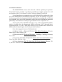
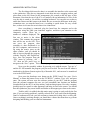
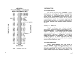
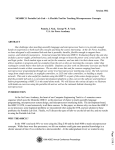
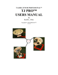
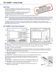
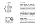
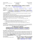
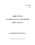
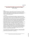
Building A Simple MIDI Controller:
A Laboratory Exercise
Charles Repetti
May 1992
A dissertation in the Department of Computer Science
submitted to the faculty of the Graduate School of Arts
and Sciences in partial fulfillment of the requirements
for the degree of Masters of Science at New York
University
Approved: _________________________
Bubhaneswar Mishra
Research Advisor
Building a Simple MIDI Controller:
A Laboratory Exercise
INTRODUCTION
This laboratory illustrates a simple method for building a Musical Instrument
Digital Interface (MIDI) controller from the ground up. It is intended for music students
who would like to build a musical instrument of their own design, but who have very
little electrical engineering or computer science background. With proper guidance, an
ambitious student should be able to complete the lab in a single three or four hour
session, although the motivated student will want to spend much more time implementing
his or her own specific design.
In this experiment, the student learns to use the MC68HCIIE9 to load and edit
code, assemble it, and download the result. Also, some simple wire wrapping is
demonstrated, and the use of a Hall Effect Transducer to activate a MIDI synthesizer is
accomplished.
Once the activation of a sensor is shown to be capable of driving a synthesizer, it
is up to the student to imagine the type of movement he or she would like to make to
create music.
THEORY and BACKGROUND
All modern music synthesizers are capable of receiving and acting. upon the same
type of signal, according to the MIDI standard. Until recently, building a controller (such
as a keyboard) was quite difficult. But with the advent of the Motorola 6811
microcontroller, the process is finally within the reach of the performing musician. The
6811 is capable of receiving a output of a typical analog device (such as a turnable knob
or a pressable lever) and translating that signal all the way to a MIDI signal.
In our example, we will pass a magnet near a sensor. This generates an increased
voltage, which the 6811 picks up and deciphers. The 6811 is then free to send the
position information to a synthesizer in a digital format which resembles an advanced
Morse code. There is an inexhaustible amount of theory concerning this process. The
interested reader is directed to the “Suggested Reading" section for more information
about this.
The important thing to keep in mind is that the placement of a magnet near a
sensor can be detected and used to play musical notes. The 6811 is designed so that more
than one sensor can be hooked up. Uncomplicated methods exist for hooking up any
number of sensors to one 6811, but the first step is just to get one working.
As many sensors are attached to one 6811, though, the device can become
overloaded. Fortunately, it is easy to hook up a number of 6811' s to one another so they
can share the work. This forms a parallel processing system, a sort of a music
supercomputer! But once again, the first step is to get one sensor working.
SUGGESTED READING
The M68HCIIEVBU comes with a box full of books explaining its operation.
These books become essential as one desires to build more complex systems. You will
need portions of the "User's Manual" and the "Reference Manual" for this lab.
A good introductory programming text would be helpful for reading and writing
6811 code, although this is not absolutely required for our lab. The offerings vary greatly.
It is best to go to your local computer bookstore and look for something that you feel you
can work'with. Also, each of the components used in this lab are included in a data book
published by the manufacturer which gives great detail as to the component's use.
Anyone who works with MIDI will want a copy of the current MIDI standard,
which is available from the International MIDI Association, 11857 Hartsook Street,
North Hollywood, CA 91607. Many other books are also available which describe the
MIDI standard in depth. Again, check with your local bookstore.
Some other suggested sources of information are:
(1) Micro Switch, a Honeywell Division Hall Effect Transducers. Freeport,
Illinois 61032: Micro Switch, 1982.
(2) Horowitz and Hill The Art of Electronics. Cambridge: Cambridge University
Press, 1989.
(3) Precision Monolithics Incorporated Linear and Conversion Products Santa
Clara, CA 95050: PMI, Inc. 1984.
(4) Texas Instruments The TTL Data Book for Design Engineers Houston, TX:
TI, Inc.1981. Motorola M68HC11 EVBU Laboratory
PRE-LAB REQUIREMENTS/EXERCISES
(1) If you could build an instrument that could be played in any way that you
desired, what such an instrument look like? Consider simplicity in your design. Can solid
materials be used instead of gears or pullies to make your design work? How could you
place magnets and sensors (see figure 2) within the design to make it work?
(2) The schematic diagram below represents the way in which the parts must be
connected to make the MIDI interface work. Using this diagram, make a drawing of
where you will place your parts using the worksheet included on the last page of this text.
Consult chapter 2 of the "M68HC11EVBU Universal Evaluation Board User's Manual"
for pin assignments on "P4" connector, and for more information about the wire wrap
area. Once you have decided where to locate your parts on the wire wrap area, draw in
lines between the exact place on each part where wire connections must be made. Be sure
to also include a sensor (see Figure 2) in your design. The legs of these sensors fit into
the holes just like normal integrated circuits. One of the sensors lies flat and responds
from a magnet nearing it from above, the other stands up and is exited from one side.
Figure 1, The Interface Schematic
(2) The MIDI standard requires an electrical current of a certain rating to transmit
information. Our power supply is 5 volts. We will be using two 220Ω resisters in a series,
and all MIDI receivers add another 220Ω for a total of 660 Ω. Also, the two gates we use
have enough resistance to bring our circuit's total impedance to about 1,000 Ω.
According to Ohm's law, we can determine that our circuit will allow a certain
amount of current to flow. The amount of current is equal to the voltage divided by the
resistance. How many thousandths of an ampere (milliamps) flow through the MIDI
current loop?
(3) The MIDI standard states that a digital signal consisting of two states (current
flow and no current flow, see exercise 1) is used like a kind of Morse code to transmit
information about musical events. This signal is transmitted according to a specific
timing, called a baud rate. In our case, this is the number of bits which are transmitted
each second. The 6811 is capable of transmitting at many different baud rates. Using
software, we have selected the proper speed.
Look at the software listing near the end of this document. Find where a constant
is stated which expresses a “MIDI baud rate”. Our M68HC11EVBU has an 8 Megahertz
(MHz) clock. Using the tables located on in section 9 of the “M68HC11 Reference
Manual”, determine the standard MIDI baud rate.
Figure 2, Hall Effect Transducers
LABORATORY INSTRUCTIONS
The first thing which must be done is to assemble the interface to the sensor and
to the synthesizer. Place the two integrated circuit chips into wire wrapping sockets, and
place them on the 6811 board in the arrangement you created on the last page of this
document. Note that the top of the IC's are marked with an indentation; be sure of the
way the chip is seated or you will do everything backward. You can also use sockets to
attach the resisters and the sensor to the board. Be sure to note the difference in the pins’
orientation once you turn the board over; everything is upside down. Be very careful
here, as there is no room for error in these wire connections.
Once everything is connected, plug the board into the computer and to the
synthesizer using the cable your instructor supplies, and direct your attention to the
computer's screen. There are a
number of windows displayed. The
first one to notice is the editor
window. This contains the program
that will be run on the 6811. First
one saves the program, then
assembles it, then downloads it to
the 6811 computer, and executes it.
By using the mouse, press on the
editor window, and you should be
able to browse through the program
with the “PageUp” and “PageDown”
keys. Save the program from the
“File” menu by pressing “Alt” +
Figure 3, The Edit Screen
“F1” then use the arrow keys to
navigate to the “Save” option. This writes the program to the computer's disk.
Now go to the assembly window by pressing on it with the mouse. Type an “a”
and the PC will assemble the program you just saved to disk. The text from the editor is
translated to the binary format required by a Motorola 6811, and can now be transferred
over to the EVBU board.
Now press the hardware reset button on the EVBU board. Use your “User's
Manual” to locate this button. Press on the "PCBUG11” window. Type “run” and press
enter. The system will now reset the software portion of your 6811, load the program
from the personal computer (the one you just assembled) into location one hundred
(hexadecimal) in the 6811's on-chip memory, and run that program. Now take a magnet,
possibly taped to a pencil or other apparatus, and bring it close to the sensor. You should
hear the synthesizer play a note louder and louder as the magnet gets closer to the sensor.
Truth be told, it is unlikely that this entire setup is going to work perfectly the first
time. If you are having problems, carefully recheck all of your work from the beginning.
Don't be embarrassed to ask your lab assistant or instructor for help; this is a tricky lab.
Once everything is working, though, you should have a better idea about how to go about
designing and building your own musical instruments.
Building a Simple MIDI Controller:
A Laboratory Exercise
INSTRUCTOR NOTES
It is probably too much to expect that the students of this lab understand
everything about the theory behind this experiment. It might be useful to discuss the
difference between analog and digital signaling. A presentation involving Ohm's law
might provide a helpful introduction to what is required to working in an engineering
domain.
It might also be interesting to review the Hall Effect, as well as photo-optical and
radio based alternatives for position sensing. Some amount of assembly language
programming will be required in a larger project, as well. If the final project is to include
a MIDI "input" or "thru" port then the topic of interrupt programming for the
Asynchronous Serial Communications Interface must be addressed.
One interesting project might involve using the sensor to generate pitch or
modulation controller information for one of the many household keyboards that were
manufactured without such a controller. The controller could be hooked up without
building a “thru” or “input” port. Since only a small number of sensors would be
required, no off-chip multiplexing would be required.
The use of the Precision Monolithics Mux-O8 as an analog multiplexer, with the
6811 data address lines as input selectors might be suggested for those students interested
in extending the number of sensors used. The 6811 Serial Peripheral Interface might also
be mentioned as a means of linking multiple processors.
Students should be encouraged to explore the application of the 6811 in musical
instruments of their own design, rather than simply extending the lab to include more
specific experiments. Music students tend to be a creative bunch, and hopefully the more
inspired amongst them will be willing to take on the discipline required to complete a
large scale project if the goal is perceived as an instrument of their own design.
PC's should be set up to run Microsoft Windows 'with an editor, an assembler,
and PCBUG11 as tasks. Note that we have found that PCBUG-11 must be in full screen
mode under Windows 3.0 to avoid dropping characters. Windows 3.1 should solve this
problem, although this release was not available when this lab was first performed. Also,
it is likely that some students will become confused by the wire wrapping process. It
would probably be helpful to check each student's wire wrap plan before work begins to
be sure it is correct, and to be sure that each student understands that once the board is
turned over, a different pin orientation will present itself.
P
A
R
T
S
L
I
S
T
Figure 4, The Assembler Window
Figure 5, The PCBUG11 Screen
1
1401
Quad Two Input NOR Gate
1
7405
Open Collector Hex Inverter 2 220 O Resistors
1
92SS12-2
or
634SS2
Hall Effect Transducer
1
Rare Earth Magnet
1
Wire Wrapping Tool and Wire
1
PC running MS-Windows, an Editor, a 6811 Cross-Assembler and
PCBUG-11.
1
MIDI Sound Generator (no keyboard required)
1
5 Pin MIDI Connector and a DIN Socket with soldered leads 1 Any
type of Sound System for the Sound Generator 1 5 Volt Power
Supply
1
Motorola M68HC11 EVBU Student Evaluation Board