1
PA7
1
20 PD0/RXD
PA6
2
19 PD1/TXD
PA5
3
18 PD2/MISO
PA4
4
17 PD3/MOSI
PA3
5
16 PD4/SCK
PA2
6
15 PD5/SS*
PA1
7
14 XIRQ*
PA0
8
13 IRQ*
RESET* 9
12 +5VDC
Vin
11 GROUND
10
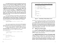
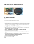
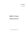
“BIRD’S-EYE” VIEW
Note:
* indicates ‘active low’
BACK
FRONT
APPENDIX B
Pinouts for SB Connector Option
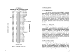
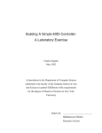
1 INTRODUCTION
1.1 Thank you...
Congratulations on purchasing MicroStamp11, the world’s
smallest 68HC11 microcontroller module! From model rocketry to
microrobotics, the applications are endless! We’d love to have you tell
us about your application. Consider joining our Support Forum for
networking with other customers using our 68HC11-based products.
Visit www.microstamp11.com for more information. Your questions
and comments are always welcome. We provide friendly, knowledgeable
technical support via email and the Support Forum to all our customers.
As well, we have a comprehensive Resource page on our website,
offering product information, software, code examples, application notes,
and links to useful sites on the Internet. Visit www.microstamp11.com.
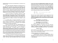
1.2 What is MicroStamp11™?
MicroStamp11 is a complete working stamp-sized computer
based on Motorola’s popular MC68HC11 microcontroller. It is a fully
functional, standalone implementation of an expanded-mode 68HC11
configuration, and can be plugged, just like a chip, into your solderless
breadboard. Then you simply wire up the desired application circuits
write your program, and download it into MicroStamp11’s memory
from your PC serial port, using the MicroStamp11 Docking Module.
Even with the power off, your program stays in MicroStamp11’s memory.
If you make some changes to your program, just download the new
file– the old one is automatically overwritten.
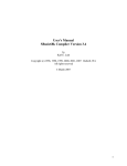
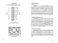
1.3 Product Description
FRONT VIEW
24
MicroStamp11 comes with on-board EEPROM program
memory (8K or 32K, depending on the version you purchased). Using
the RS232 interface provided by the Docking Module (or a
ComStamp232), MicroStamp11’s memory is directly loadable via your
PC serial port (i.e. ComPort) for quick and easy programming. For
newer PCs which have only USB ports, you’ll need a USB-to-Comport
adapter, such as our USB2COM product, available from most computer
stores.
1
REV.2J
MicroStamp11 satisfies the needs of users who want lots of
memory, but only require a modest number of I/O lines, and no
analog-to-digital converter (analog-to-digital converters and extra I/O
lines are very easy to add via SPI, however). With the 68HC11’s
hardware timer subsystem, implementing motor control, tone generation,
pulse-width modulation, pulse-width measurement, and communication
are just a few examples of what is easily achievable. Because of the
68HC11’s powerful hardware interrupt system, all of the above functions
can be easily multi-tasked, and achieved in real-time. This is a very
important advantage over popular PIC-based modules, which are
basically “one-trick ponies” (albeit, fast ones)! There is a lot more
software overhead and complexity involved in getting a PIC to do
multiple simultaneous tasks, and respond to multiple asynchronous
events. In fact, PIC-based modules in the same price range as
MicroStamp11 are simply not able to match the real-time control and
mult-tasking capability of MicroStamp11.
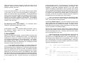
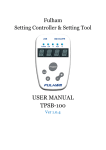
1.5 Serial Ports
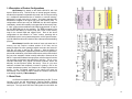
68HC11D0 INTERNAL BLOCK DIAGRAM
MicroStamp11 is based on the 68HC11D0 MCU, with 192
bytes of RAM on-chip. This MCU has no internal program memory,
and therefore operates in expanded-chip mode, with 16 of its pins acting
as a multiplexed address/data bus to interface to external memory,
along with a couple more pins for control. An industry-standard 32K
EEPROM is mapped to the upper half of the 64K memory map. In
configurations which have only 8K EEPROM, the 8K block appears
redundantly, at each 8K boundary in the upper half of the memory map.
A “64K” version with an additional 32K RAM “piggy-backed” on top of
the 32K EEPROM chip is also available. The RAM is mapped in the
lower half of the 68HC11’s memory map, with “holes” in the memory
map for the internal RAM and register block. Each of the above
configurations is also offered in a “Turbo” version, operating with a
9.8304 MHz crystal. Among its advantages are: a 23% speed increase,
up to 38.4Kbaud serial communications rate, and a speedier bootloading
process.
MEMORY MAP
1.4 Description of Product Configurations
An RS-232-compatible 3-wire serial interface port (RX, TX, and
Ground) is built into the MicroStamp11 Docking Module, allowing
communication with a PC, or any other device which has an RS-232
serial port. The logic-level RXD and TXD signals from the MCU are
2
23
available on MicroStamp11’s connector, for applications such as
RS-485 or MIDI. Of course, if your application doesn’t need
communication, these two pins can be configured as general purpose
I/O lines. For applications where the Docking Module is too big to be
practical, a miniature RS232 interface board called COMStamp232 is
available. Check www.microstamp11.com for details.
The 68HC11’s industry-standard Serial Peripheral Interface
(SPI) provides an excellent means of expanding the capabilities of
MicroStamp11 to suit more demanding applications. There are many
SPI-compatible chips available, including analog-to-digital converters,
serial EEPROMs, UARTs, display drivers, and shift registers, to name
just a few. Examples for interfacing these devices can be found on the
Resources page of www.microstamp11.com.
1.6 The Big Picture
With MicroStamp11, all of the 68HC11’s available I/O lines
and control signals are brought out to a standard 20-pin interface
connector. With several different connector options available, you can
use the module in whatever way best suits your needs.
A female right-angle connector (option -FRA) is supplied as
the default option for the MicroStamp11 supplied in the Starter Package.
With the adapter supplied (ADIDC20-M), you can use the module like
a big chip, plugging it right into your breadboard. A ribbon cable is
supplied so that you can keep MicroStamp11 in the Docking Module
during development, and plug its I/O pins into the breadboard via the
ribbon cable/adapter combination. Forget soldering or wire-wrapping–
get started developing your application right away. Your prototyping
space is virtually unlimited, using solderless breadboards! Once you
have your design working and you’re ready to move to something more
permanent, you can incorporate one of the supplied mating connectors
into your design, and just plug MicroStamp11 into it. MicroStamp11
becomes a sort of modular “brain” that you can plug into many different
projects you develop.
68HC11D0 REGISTER BIT SUMMARY
22
3
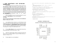
2 USING MICROSTAMP11 WITH SOLDERLESS
BREADBOARDS
As mentioned previously, the standard connector style on your
MicroStamp11 is “FRA”, which stands for “female right-angle”. Plug
it into the supplied adapter, and it can straddle the center channel of a
solderless breadboard, providing several tie-points associated with
each pin. This allows you to plug in wires and other components such
as resistors and LEDs, to build your application If your board has a
different connector option, you can still use it with a solderless breadboard,
by way of the appropriate 20-pin solderless breadboard adapter. See
the MicroStamp11 Accessories page on our website,
www.microstamp11.com.
Refer to Appendix B and the enclosed schematic for pinout
information for MicroStamp11 and its Docking Module.
CAUTION!
Never insert your module into or remove it from a “live” breadboard.
Make sure the power is OFF !
1)
Any breadboard will do; however, you will find that the kind
made with a softer, more pliable plastic (such as nylon) will be easier
to use and more durable. It is recommended that you dedicate a section
of your breadboard to the MicroStamp11 adapter, since its square
pins may cause the breadboard spring contacts to spread eventually,
so that they will no longer hold small-diameter wires.
•Microcontrollers: Architecture, Implementation, & Programming
- Kenneth Hintz and Daniel Tabak - ISBN 0-07-028977-8
- 1992, McGraw-Hill Inc.
•Mobile Robots: Inspiration to Implementation
- Joseph L. Jones and Anita M. Flynn - Very hands-on book.
- Detailed design & construction of “Rug Warrior”
•Programming Microcontrollers in C
- Ted Van Sickle - ISBN 1-878707-14-0
- 1994, HighText Publications - 394 pages
- thorough tutorial on C programming, covers aspects of C programming
specific to embedded systems
•MC68HC11: An Introduction
- Han-Way Huang - West Publishing
- ISBN 0-314-06735-3
•The M68HC11 Microcontroller: Applications in Control, Instrumentation and Communication
- Michael Kheir
- Prentice Hall
APPENDIX A - REFERENCE DATA
Pinouts for Surface Mount Package of 68HC11D0
2)
First plug MicroStamp11 into the vertical 20-pin connector on
the Docking Module, lining up the white pin 1 dots.
68HC11D0
3)
Attach the supplied ribbon cable by plugging the strain relief
end into P2 of the Docking Module, lining up the ribbon cable pin 1
indicator to P2’s pin 1 dot.
4)
4
Plug the adapter into your breadboard.
21
5.0 SOURCES
Internet Resources
•Technological Arts: www.microstamp11.com
5)
Plug the other end of the ribbon cable into the adapter, with
the pin 1 indicators lined up. For convenience, you may want to place
additional breadboard sections in parallel on each side for easier wiring
of your circuits
• Freescale: www.freescale.com
Freescale Publications
•M68HC11 Reference Manual (M68HC11RM/AD)
•M68HC11 E-series Technical Data book (MC68HC11E/D)
•Single- and Multiple-Chip Microcomputer Interfacing
(Prentice-Hall or Motorola TB316; Lib. of Cong. Cat. # 87-60656)
Other Books
•The 68HC11 Microcontroller
- Joseph D. Greenfield (at R.I.T.) - ISBN 0-03-051588-2
- 1992, Saunders College Publishing, (Harcourt Brace Jovanovich)
•Data Acquisition & Process Control w/ the M68HC11 Microcontroller
- Frederick Driscoll, Robert Coughlin, Robert Villanucci of
Wentworth
Institute of Technology.
- 1994, Macmillan Publishing Company
- ISBN 0-02-33055-X
- example applications of interfaces to various sensors.
•Design with Microcontrollers
- John B. Peatman (professor at Georgia Tech)
- ISBN 0-07-049238-7
- This book is on a more advanced level. Uses both the 68hc11
and Intel 8096 as example systems.
•Embedded Systems Programming in C and Assembler
- John Forrest Brown
- ISBN 0-442-01817-7
- Van Nostrand Reinhold, 1994 - 304 pages, $49.95
- covers Motorola and Intel processors
•Microcomputer Engineering
- Gene H. Miller
- ISBN 0-13-584475-4
- 1993, Prentice Hall, Englewood Cliffs, NJ 07632
- Explains basics. Many clear, concise examples.
•Microcontroller Technology, The 68HC11
- Peter Spasov
- ISBN 0-13-583568-2 - Prentice Hall
20
6)
Choose a convention for wiring your power distribution buses.
A logical approach is to make the inside bus logic 5V, and the outside
buses GROUND.
There are two ways to power MicroStamp11 Supply regulated
5V power to the +5V pin (pin 12), or supply an unregulated DC voltage
in the range of 7 to 12V to the Vin pin (pin 10). The DockingModule
provides a convenient connector for this purpose. A DC adapter or 9V
battery will work fine.
Note that if you supply a voltage to Vin, the +5V pin becomes
an output, supplying regulated 5V from the on-board regulator, which
has some excess capacity to power your circuits in addition to
MicroStamp11’s. No matter which approach you use, always connect
your circuit GROUND to MicroStamp11 GROUND.
7)
If you are using voltages other than 5V in your application,
make sure to keep these well away from MicroStamp11 pins and
tie-strips, to avoid accidental shorts which may damage the module.
3 TUTORIAL
Note that this manual is not meant to provide an exhaustive
study of the 68HC11, but rather to help you get started using
MicroStamp11 as a learning and application development tool for
68HC11, whether you’re a beginner or an expert. If you are a beginner,
you will benefit from additional material listed in the Reference section
of this manual, and links provided on the Applications, Tech Support,
and Resources pages of our website (see back cover for URL).
3.1
Getting Started
Important! Be sure to browse the README.TXT file on your
Starter Package disk for information on what’s on the disk and how to
use it. Use any text editor or browser you like, such as Notepad or
DOS edit, and follow the instructions for copying the disk contents onto
your hard drive.
5
If you have a Windows computer, you should also install the
MicroLoad application, included with your package. Check the
RESOURCES page on our website to make sure you have the latest
version. MicroLoad is the recommended utility for loading your program
into MicroStamp11’s memory.
MicroStamp11 has a demo program already programmed into
the EEPROM when you receive it. This is a useful program for testing
your communications setup and monitoring and controlling the various
I/O lines of the MCU.
Plug MicroStamp11 into the Docking Module, and supply power
via the external power connector. Just connect a DC voltage of 5V or
higher (up to 12V) to the external power connector (J1) on the Docking
Module. Red is positive, and black is negative (ground). CAUTION!
Make sure you have the polarity correct!
To use the demo program, connect the supplied serial cable
between the Docking Module and a serial port on your PC. (With some
PCs, you will need a 9-pin to 25-pin adapter.) Run a terminal program
(such as TeraTermPro, or the Windows HyperTerminal program) on
your PC. In your terminal program, set the baud rate to 9600 (38400
for “Turbo” versions), parity to NONE, #DATA BITS = 8, and #STOP
BITS = 1, and “no handshaking”. With SW2 set to RUN, press the
Docking Module RESET button. LED D2 will blink twice, indicating the
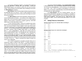
demo programming is running. Hit <ENTER> on your keyboard. A
menu of commands will appear on your terminal window’s screen,
followed by a command prompt “?” symbol. Each command is activated
by a single keystroke. A sample screen showing results of each command
is shown in Figure 3.1. Typing a command not listed will cause the
menu to be re-displayed.
The A and D commands in the demo program allow you to
examine the states of PORTA and PORTD. Try putting switches on
some of these input port lines. Use a 10K or higher pullup resistor on
one side and connect the other side of the switch to ground. Note that
PA0-PA2 are inputs, PA3 and PA7 are programmable as input or output,
and default to inputs. PA4-PA6 are outputs only. In the demo program,
PA6 is used as a tone output for a speaker. It is also connected to
LED D2, when plugged into the Docking Module, to provide a visual
output. You can drive a small piezo speaker directly by hooking one
end to PA6 through a 330-Ohm resistor, and the other end to ground.
When you press RESET, or type “S” when the demo program is running,
6
To compile and download hello.c, select Compile to Executable
in the pulldown menu. ICC11 will compile, assemble, and link, creating
an s-record file called hello.s19. This is the file you will download to
your board. ICC11 does not support downloading to the D-series
68HC11, so you’ll need to use MicroLoad (or one of the DOS batchfiles
included with your starter package).
Plug MicroStamp11 into the Docking Module, and use
MicroLoad to download the s-record you just created (or use pms1 or
pms2 from DOS). Press the RESET button and slide the Write Protect
switch (SW3) to WRITE. Then press any key. When finished, slide
SW3 back to PROT, SW2 to RUN, and press RESET to run your
program.
4.5
Handy Reference Information
Baudrate Settings for Standard MicroStamp11
Value Speed
$30
9600
$31
4800
$32
2400
$33
1200
Baudrate Settings for Turbo MicroStamp11
Value Speed
$20
38400
$21
19200
$22
9600
$23
4800
$24
2400
$25
1200
Port A
PA0
Input
PA1
Input
PA2
Input
PA3
I/O
Set by bit 3 of PACTL (Default: Input)
PA4
Output
PA5
Output
PA6
Output
PA7
I/O* Set by bit 7 of PACTL (Default: Input)
*Note- there is a typo regarding this bit in the HC11D3
Programming Reference Guide
19
The LINKER is the part of a compiler package that marries the
software with the particular hardware configuration being used.
Therefore, you need to setup the LINKER before using ICC11. Find
the Linker setup tab by pulling down the OPTIONS menu to COMPILER.
In the Linker, “text” refers to code, and should be the starting address
of EEPROM (or wherever you plan to put the code); “data” is for
variables, and should be the start of RAM; “stack” should be the end
of RAM, since it builds “downward”. For MicroStamp11, you would
set “text” to 0xE000 (for 8K EEPROM) or 0x8000 (for 32K EEPROM).
Set “data” to beginning of RAM ( 0x40), and “stack” to end of RAM
(0xFF). For ICC11 Version 6 or later, selections already exist for
MicroStamp11 variants in the list of targets, so you can just select the
variant you are using.
Since the register block in D-series 68HC11chips starts at 0x00
instead of 0x1000, as in E-series chips, you’ll need to add a line of
code to initialize the register map to 0x1000. You should also clear
the CONFIG register (i.e. write 0x04 to CONFIG), disabling the COP.
So here is what you need to add at the beginning of your program:
void _HC11Setup(){
*(unsigned char volatile *)(0x3D) = 0x01;
CONFIG = 0x04;
}
Also, every C program that you write requires the file vectors.c
to be included (either explicitly at the end of the program, or as the last
file in the Project, if you are using the ProjectBuilder feature of ICC11)..
To get you started with ICC11, examine, modify, and compile
the program hello.c, in the Examples directory of ICC11. This program
has the essentials set up for you. Modify it to look like this:
#include<hc11.h>
void _HC11Setup(){
*(unsigned char volatile *)(0x3D) = 0x01;
CONFIG = 0x04;
}
main()
{
setbaud(0x30);
puts("Hello World\n");
while(1)
}
#include "vectors.c"
18
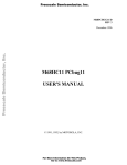
MICROSTAMP11 DEMO PROGRAM COMMAND MENU
A => SHOW PORT A STATUS
C => CLEAR PORT A OUTPUTS
D => SHOW PORT D STATUS
S => BEEP SPEAKER (CONNECT TO PA6)
?
<A>
PORTA=000
<D>
PORTD=001
<S>
>>> BEEP! <<<
Figure 3.1
MicroStamp11 Demo Software Screen
you will hear two beeps from the speaker (or the LED will flash twice).
Typing a digit between 4 and 6 causes the output state of the
corresponding PORTA line to be toggled (eg. typing 5 causes PA5 to
flip to a high if it was low previously, or a low if it was high previously).
This allows you to activate LEDs (when driving LEDs directly from an
output port, limit the current to a maximum of 10mA with 330-Ohm
current limiting resistors on each LED); or drive relays, solenoids, or
motors (with appropriate driver circuits).
3.2
Writing Your First Program
If you are already experienced with the 68HC11 family of
microcontrollers, you can skip this section. However, you may find the
suggestions here useful to familiarize yourself with the essentials of
getting a program to work the first time.
As mentioned in the previous section, a demo program resides
in MicroStamp11’s EEPROM when you receive it. This demo program
is written in Motorola’s Freeware AS11 cross-assembler syntax, and
is intended to provide you with an easy way to verify your hardware
setup (ie. power supply, serial connection, PC software, etc.). It also
provides you with an excellent starting point for developing your own
program. Rather than starting from scratch, you can make a copy of
7
the demo source file and remove and add features, to transform it into
what you need.
Many people approach programming by spending hours or
even days writing a program from scratch, then assembling it and
downloading it. Then they cross their fingers and reset the board,
praying everything will work. About 99% of the time, their hopes are
dashed, as the board does something completely different than they
expected, or worse– it appears to do nothing! At that point, they either
give up, or purchase expensive diagnostic equipment, such as logic
analyzers and in-circuit emulators to begin the long hard road of
diagnosing and correcting their software and/or hardware mistakes.
A much more sensible– and rewarding– approach is to start
with something that works, and then add new features incrementally.
The modular design of MicroStamp11 gives you that starting point-hardware that works, and software that works. Now, if you build on
that incrementally, each diagnostic step is small and manageable. And
it will probably end up taking a lot less time, and costing a lot less
money.
A powerful asset for program development is the serial
communications interface (SCI). The SCI gives you a window on what’s
going on inside the microcontroller. Simple diagnostic messages,
placed at strategic points in your evolving program, will be invaluable
in debugging your software and hardware.
If you look at the demo source code (ms11demo.asm), you
will see that it consists of an initialization section, one main loop, and
several subroutines and interrupt routines. The main subroutine is
called ProcessCommand. Its primary function is to interpret a
single-character command that is received via the serial port, and
perform the appropriate action for that command. You can easily extend
the list of commands within the ProcessCommand subroutine by adding
code to recognize and process other single-character commands you
define. Then it is simply a matter of writing those subroutines to perform
the functions you wish to implement. This software structure gives you
a way to independently test each new function one at a time.
For example, let’s suppose you are implementing an autonomous
vehicle, using a miniature toy car. You will need to read position and
collision sensors, and control the speed and direction of one or more
motors. First write a basic motor-speed control routine, and assign
8
lines of code into the special start11.lib file that SBASIC uses for every
program you compile. Doing this will ensure that the HC11 register
block will always appear in the memory map at $1000, regardless of
which flavor of HC11 chip is being used. The point of all this is to
ensure that the SBASIC library routines will function on MicroStamp11
without modification. You may also want to write $04 to the CONFIG
register in start11.lib to disable the COP watchdog if you’re not using
it (for more on the COP, refer to the HC11 Reference Manual). The
code to add at the beginning of start11.lib is shown below:
ldaa #1
staa $3d
;move register block to $1000
ldaa #4
staa $103f ;disable COP
Below are some example configurations and the approprate /c and /v
compiler options used to specify the starting addresses for code
(EEPROM) and variables (RAM), where infile is your SBASIC program
filename, and outfile is the name you want the target assembly language
file to be called.
MicroStamp11 with 8K EEPROM:
sbasic infile /ce000 /v0040 /s00ff >outfile.asc
MicroStamp11 with 32K EEPROM:
sbasic infile /c8000 /v0040 /s00ff >outfile.asc
The resulting file outfile.asc is in assembler source code, and can be
viewed and edited if you wish. When ready, assemble the file with
ASMHC11 (included in the SBASIC distribution file) to produce an
s-record file suitable for downloading to your board. Use it as follows:
asmhc11 outfile
and it will produce the file outfile.s19.
Now you can use MicroLoad (or the pms DOS batchfile mentioned
earlier) to load it into MicroStamp’s memory.
4.4 Using ImageCraft’s ICC11 Windows C Compiler.
ImageCraft offers a good low-cost ANSI C compiler, which is
quite popular in the 68HC11 community. The following section provides
some basic hints and guidelines for setting up ICC11 and using it with
the MicroStamp11.
17
Down arrow keys to make the changes, or enter new values via the
keyboard. When you’re done, press the ESC key to return to the
PCBUG11 prompt. Now enter:
term
to open the terminal window. If you have the Demo program loaded
in your board, you can use the terminal window to interact with it.
Switch your board to RUN, and press RESET. Pressing ENTER will
cause the menu of the demo program to be displayed. Select the menu
commands, as you desire. When you have finished using the demo
program, you can return to PCBUG11 by hitting ESC. To re-establish
communication between PCBUG11 and the ‘HC11, reset your board
in BOOT mode, and enter:
restart
4.26 Exploring Further with PCBUG11. For information about
PCBUG11 commands and their syntax, enter:
help
at the PCBUG11 prompt. For complete details on PCBUG11, refer to
the PCBUG11 Manual (found on the Resources page at
www.microstamp11.com.
4.3 Using SBASIC
SBASIC is a DOS-based compiler. It takes a BASIC text file as input
and produces a 68HC11 assembler file as output. You assemble the
resulting file to produce an s-record file (with extension .s19), which
you can load into MicroStamp11 as described earlier. If you haven’t
used SBASIC before, make sure you read through the excellent
documentation included in the distribution file, to familiarize yourself
with what it’s all about and how to use it.
To use SBASIC with MicroStamp11, you will first need to deal
with the unique default register block address of the D-series 68HC11.
As mentioned previously, it defaults to 0. By contrast, all E-seies chips
default the register block address to $1000, and SBASIC assumes
you’re using an E-series chip. One way to deal with this it to change
IOREGS to 0 in the first line of the file HC11REGS.LIB. But a better
alternative would be to re-locate the register block to $1000 immediately
after reset. This can be done by adding two lines of code at the beginning
of each program you write. An even easier way is to put those two
16
some commands to test it. You could assign “F” for faster (increase
the motor speed), and “S” for slower (to decrease motor speed). Then
implement a pulse-width modulation scheme in your motor speed
routine, decreasing the pulse-width by some increment every time the
“S” key is pressed, and incrementing pulse-width by the same amount
every time the “F” key is pressed. Of course you will want to put tests
for minimum and maximum pulse-widths before you decrement or
increment, so that the motor doesn’t suddenly jump from stopped to
full speed when the pulse-width value “wraps” around.
Note: If you plan to incorporate all or part of the demo program
in your own code, and you’re using a different cross-assembler than
AS11, you may have to revise the syntax.
3.21 A Very Simple Program If you are a beginner, the size of the
demo program may look overwhelming, and you may wonder what is
really required just to do something very simple. In reality, you can
throw away almost everything, ending up with about a half dozen lines
of code, to produce a very simple program.
Rule #1: Every program requires a Reset Vector (located at $fffe and
$ffff), since the contents of these locations is loaded into the Program
Counter immediately after reset. Therefore, the Reset Vector should
point to the beginning of your code.
Below is an example of a very simple program, which just turns
on the LED on PORTA (PA6), and then waits in an infinite loop. (It
was written for an 8K EEPROM space, so if your board has 32K, you
can change the org to $8000, but it’s not necessary). Note: the MCU
has a watchdog timer (COP) which is enabled by default. Unless you
plan to use this feature, you need to disable it (NOCOP bit in CONFIG
register) at the beginning of your code.
org
begin:
ter
staa
ldaa
staa
bits)
bra
$e000 ;start at top 8K EEPROM
ldaa
#$04
;disable COP in CONFIG regis-
$3f
#$40
$0
;write logic high to PA6
; (and logic low to all other portA
*
;branch forever (until reset occurs)
9
org
fdb
$fffe ;define the reset vector to point to
begin ; the beginning of your code
4.22 Verifying an S-record File in EEPROM. Suppose you have
loaded a file called myprog.s19, use the following command to verify
it is in EEPROM:
verf myprog
3.22 Adding a Little Complexity. Now let’s take it one more step:
blink the LED on and off. To make the blinking slow enough to perceive
with the human eye, we will write a subroutine to create about a
half-second delay.
Rule #2: If you are using interrupts, or incorporating any subroutines
in your program, you must initialize the stack pointer at the beginning
of your program.
org
begin:
ter
staa
lds
loop: ldaa
staa
bits)
bsr
clr
bsr
bra
Delay:
ldy
D1:
dey
iny
dey
8MHz
bne
rts
org
fdb
10
$e000 ;start of top 8K EEPROM
ldaa
#$04
;disable COP in CONFIG regis-
$3f
#$ff
#$40
0
;initialize the stack pointer
;write logic high to PA6
; (and logic low to all other portA
Delay ;do a time delay
$0
;make all portA bits logic low
Delay
loop ;do it all again
#$ffff
;pad delay loop with extra cycles
; for total of 15 cycles
;this gives approx. 1/2 second at
D1
If it is in a different directory, (eg. c:\myfiles) you should specify the
directory path. For example:
verf \myfiles\myprog
restart
To run your program, reset MicroStamp11 in RUN mode. To use
PCBUG11 again, reset your board in BOOT mode, and type:
restart
Again, switch on access to external memory with:
ms 3c e5
4.23 Manipulating Memory. To change the value stored in a RAM or
register location (eg. clear RAM location $f0), simply use the Memory
Set command, as follows:
ms f0 00
To alter an EEPROM location, you need to slide switch SW3 to WRITE.
You can then modify it with Memory Set (as above), or with the Memory
Modify command, as follows:
mm e000
In this example, PCBUG11 will display the current value of location
$e000. If you wish to change it, type the new value, and press ENTER.
If not, just press ENTER. The next memory location will be displayed.
To end the Memory Modify mode, press ESC on your keyboard.
4.24 Using PCBUG11’s Terminal Window. PCBUG11 has a basic
communications terminal which is useful for testing and debugging your
software. To use it, set up the necessary communications parameters
such as baud rate, parity, etc. by entering:
control
$fffe ;define the reset vector to point to
begin ; the beginning of your code
A list of parameters is displayed. Use the Page Down and Page Up
keys to move to the parameter that needs changing. Use the Up and
15
pms2 myprog
4.2 Using PCBUG11 with MicroStamp11
Motorola’s PCBUG11 is a flexible, powerful, and easy-to-use
program that runs on a PC under DOS. It allows you to examine and
modify register contents, RAM and EEPROM, debug, trace, disassemble
blocks of code, assemble line-by-line, and even includes a basic terminal
program. What’s more, it works with all varieties of HC11 micros, and
is fully compatible with MicroStamp11. PCBUG11 is included on your
Starter Package disk, and is also available on the Resources page of
our website. It is a self-extracting archive, so just copy it to the directory
on your harddrive where you want it to reside, and type pcbug342 at
the DOS prompt to extract all the files.
4.21 Running PCBUG11. Always RESET your module in BOOT mode
before starting PCBUG11. It is important to make sure there are no
background tasks running on you PC, such as faxmodem drivers,
networks, etc. PCBUG11 needs to access the serial port chip of the
PC directly, and does not co-exist very happily with other programs.
Whenever possible, start PCBUG11 directly from DOS (not a DOS
shell). If you can’t get it to work at all, visit the Support Library on our
website for tips on troubleshooting PCBUG11.
To run PCBUG11, type the following command at the DOS
prompt (after resetting MicroStamp11 in BOOT mode):
pcbug11 -d port=2
(if you’re using COM1, omit the port=2 parameter; if you have a “Turbo”
MicroStamp11, add the parameter baud=9600).
If you prefer to use hexadecimal numbers in your PCBUG11
session (instead of the default decimal notation), enter the following
command at the PCBUG11 prompt:
control base hex
Enable access to external memory by changing mode via the HPRIO
register, and disabling internal ROM via the CONFIG register:
ms 3c e5
ms 3f 04
14
CAUTION! Avoid powering up MicroStamp11 with the
WRITE PROT switch in the WRITE position. If you do so,
one or more external EEPROM locations may get
inadvertently corrupted. If this happens, your code may not
work as intended, and you’ll have to repeat the downlaod
procedure again. In rare cases, it’s also possible to enable
the Software Data Protection feature of the memory chip,
making it impossible to load a new program.
3.3
Downloading Your Code
If you are using a Windows computer, we recommend you
install and use our MicroLoad application to download your files. It is
included with your Starter Package and also available on the
RESOURCES page of our website. If you prefer to use DOS instead,
read on. Otherwise skip to the next section.
Once you have assembled your code with no errors, you can
download the resulting s-record file (filename.s19) to your board using
the appropriate DOS batch file provided. Connect the supplied serial
cable between connector J2 on your Docking Module and COM1 or
COM2 of your PC. (You can use a different COM port, but you will
need to edit the batchfile to reflect the COM port number you use).
Use pms1.bat (for COM1) or pms2.bat (for COM2). For “Turbo”
versions of MicroStamp11, use pms91.bat or pms92.bat, respectively.
If required, use a text editor to modify these batch files to suit your
needs. On a Windows95/98 system, you may have to add \dev\ to
every reference to the com port path (eg. copy %1.s19 \dev\com1).
You may find using the batchfile more convenient if you put it
into your working directory, along with the assembler or compiler you
are using, and the source code you are writing. Make sure to put the
associated boot file in the directory as well (for example, msload.bin
is required by pms1.bat and pms2.bat).
Always reset the board in BOOT mode and slide the WRITE
PROT switch (SW3) to WRITE just before you download. During
downloading, the red LED comes on and pulses while s-records are
being loaded. When all the s-records have loaded, the LED goes off.
Switch SW3 back to PROT, and switch SW2 to RUN mode. Press
RESET to start your code running.
11
3.4
MicroStamp11 Memory Map
Appendix A shows a diagram of the MicroStamp11 memory
map. For more details of the MCU’s internal memory, register definitions
and their locations, refer to the 68HC11D3 Programming Reference
Guide. Note that the internal MCU memory blocks such as RAM and
registers take priority over any external devices mapped into their
address space. In some situations, you may wish to move the internal
RAM and/or Register Block to a different 4K address boundary. The
Register Block defaults to the range $00 to $40, placing it within the
first 256 bytes of the memory map. This allows use of the direct
addressing mode of the 68HC11, making assembly-language coding
simpler and more efficient. Internal RAM in the 68HC11D0 defaults to
the range $040 to $ff. If you have a 64K version of MicroStamp11,
external RAM will be accessible from $100 to $7fff.
3.5
About the On-board Voltage Regulator
MicroStamp11 uses a low-dropout LM2931Z-5 regulator in a
TO-92 package, capable of dissipating about 500 mW at room
temperature. It has some nice features, such as a very low quiescent
current, and will work with an input voltage down to 5 Volts (or below),
making it quite well-suited to battery operation. It is also designed to
withstand reverse polarity and, if unused, does not present a load to
an external regulated 5-Volt supply applied via the 20-pin header H1.
One drawback, however, is that it can become unstable and start to
oscillate at low temperatures, especially if the input voltage source is
connected via long wires. In the former circumstance, the on-board
10uF tantalum capacitor can be replaced with a higher value (47uF or
100uF). To compensate for long lead-in wires, add capacitance of
100uF or so at, or close to, the Vin and GROUND pins on the H1
connector.
4
REFERENCE
4.1 How EEPROM is Programmed
MicroStamp11 uses parallel EEPROM for program storage,
and requires only an RS232 interface and power to program, using the
MCU in Special Bootstrap mode to erase and load code via any serial
port. This means you can re-program your code easily, without the
need for special programming boards or erasers. This approach results
in a low-cost, easy-to-use configuration suitable for education and new
product development.
Special Bootstrap Mode. All 68HC11 MCUs contain an internal
bootstrap loader program in ROM. This program runs whenever the
chip is powered up or reset with the mode select pins configured for
Special Bootstrap mode (see Motorola 68HC11 Reference Manual for
details). This configuration can be selected on MicroStamp11 by
placing the BOOT/RUN switch in the BOOT position. When the RESET
button is pressed (or when a power-on event occurs), the MCU executes
the internal bootstrap program (a bootloader ROM source code listing
for the 68HC11D0 can be found on the Starter Package disk). It first
initializes the serial port (SCI), and waits in a loop checking its receive
buffer until it gets a value of $FF (BREAK control character). It uses
that character to determine the incoming baudrate, and adjusts its
BAUD register accordingly. It then places each byte it receives in RAM,
storing them sequentially, starting at address $40 and continuing to
address $ff (a total of 192 bytes) or until a timeout delay has elapsed
with no characters arriving at the serial port. At this point, the internal
bootstrap program loads the Program Counter with $40, causing the
CPU to begin executing the program just loaded into RAM. Thus, the
program that you have just downloaded begins executing. This feature
of the 68HC11 allows an EEPROM erase/write routine to be placed in
RAM and executed automatically. A bootloader ROM listing is provided
so that the user can take advantage of some of the special features
provided by this program. Routines for programming external
EEPROM/RAM (in expanded mode) from an s-record file are included
on your MicroStamp11 Starter Package disk. The source code file is
called msload.asm.
To program the EEPROM from a DOS prompt, use pms1.bat
(for COM1) or pms2.bat (for COM2). For example, to download your
S-record file called myprog.s19 to MicroStamp11, via COM2, at the
DOS prompt, you would enter:
12
13