Download SBE 11plus V2 Manual - Sea

Transcript
User Manual
Release Date: 02/09/2015
SBE 11plus V2 Deck Unit
For use with SBE 9plus CTD
Front Panel – switches & LEDs
Manual version
Firmware versions
Software version
•
•
•
•
•
•
•
017
Digital 5.2 & later
Modem 2.0c & later
Receiver 2.1 & later
Remote Output 1.0 & later
Seasave V7 7.23.2 & later
SBE Data Processing 7.23.2 &
later
Back Panel – connectors & fuses
Limited Liability Statement
Extreme care should be exercised when using or servicing this equipment. It should be used or serviced
only by personnel with knowledge of and training in the use and maintenance of oceanographic
electronic equipment.
SEA-BIRD ELECTRONICS, INC. disclaims all product liability risks arising from the use or servicing
of this system. SEA-BIRD ELECTRONICS, INC. has no way of controlling the use of this equipment
or of choosing the personnel to operate it, and therefore cannot take steps to comply with laws
pertaining to product liability, including laws which impose a duty to warn the user of any dangers
involved in operating this equipment. Therefore, acceptance of this system by the customer shall be
conclusively deemed to include a covenant by the customer to defend, indemnify, and hold SEA-BIRD
ELECTRONICS, INC. harmless from all product liability claims arising from the use or servicing of
this system.
2
Manual revision 017
Declaration of Conformity
3
SBE 11plus V2
Manual revision 017
Table of Contents
SBE 11plus V2
Table of Contents
Limited Liability Statement ................................................................ 2
Declaration of Conformity .................................................................. 3
Table of Contents ................................................................................. 4
Section 1: Introduction ........................................................................ 7
About this Manual .............................................................................................7
Unpacking SBE 11plus V2 ................................................................................8
Section 2: Description of SBE 11plus V2 ........................................... 9
System Description ............................................................................................9
Deck Unit Specifications .................................................................................11
System Communications .................................................................................12
Deck Unit Front Panel .....................................................................................13
Deck Unit Back Panel ......................................................................................15
Cables ..............................................................................................................16
Section 3: Mounting and Wiring System ......................................... 19
Cable, Winch, and Deck Gear (not supplied by Sea-Bird) ..............................19
Mounting Deck Unit ........................................................................................19
Wiring System .................................................................................................20
Sea Cable from Deck Unit to CTD ...........................................................20
Computer to Deck Unit .............................................................................20
NMEA Navigation Device to Deck Unit ..................................................20
Surface PAR Sensor to Deck Unit ............................................................21
Deck Unit to Remote Output ....................................................................21
Deck Unit to Serial Data Uplink ...............................................................21
CTD to Auxiliary Sensors and Water Sampler .........................................22
Power to Deck Unit ..................................................................................22
Section 4: Installing and Using Sea-Bird Software ......................... 23
Installing Software ...........................................................................................23
Using Seaterm ..................................................................................................24
Using Seasave ..................................................................................................26
Using SBE Data Processing .............................................................................28
Section 5: Setting Up System............................................................. 30
Setting Operating Parameters in Seaterm ........................................................30
Commands Entered with Seaterm.............................................................31
Setting Up CTD Configuration (.xmlcon or .con) File in Seasave ..................33
Section 6: Setting Up NMEA Interface ............................................ 35
NMEA Interface Commands ...........................................................................36
Commands Sent by User with Seaterm ....................................................36
Commands Sent Automatically by Seasave..............................................36
Setting Up NMEA in Seaterm .........................................................................37
Setting Up and Testing NMEA in Seasave ......................................................38
Troubleshooting NMEA Interface ...................................................................39
Problem 1: NMEA LED Not Flashing, or NMEA LED Flashing but
Lat/Lon Data Not Displaying ...................................................................39
NMEA Message Simulation Program..............................................................39
NMEA Navigation Device Message and Data Formats ...................................41
Message Formats ......................................................................................41
Data Formats .............................................................................................42
4
Manual revision 017
Table of Contents
SBE 11plus V2
Section 7: Setting Up Surface PAR .................................................. 43
Surface PAR Commands .................................................................................43
Setting Up Surface PAR and Adjusting for Drift in Seaterm...........................43
Setting Up CTD Configuration (.xmlcon or .con) File in Seasave ..................44
Surface PAR Data Format ...............................................................................44
Section 8: Setting Up Remote Output .............................................. 45
Pressure Frequency and Pressure Temperature ................................................45
Pressure Frequency and Pressure Temperature Commands .....................45
Pressure Frequency and Pressure Temperature Data Format....................45
Converted Data Output (CDO) ........................................................................46
Calibration Coefficients and PROG11V2 .................................................46
Configuring CDO .....................................................................................47
CDO Commands Entered with Seaterm ...................................................48
Converted Data Output Data Format ........................................................52
Section 9: Setting Up Water Sampler .............................................. 53
Setting Deck Unit Receiver/Modem PCB Dip Switches .................................53
Setting Up Water Sampler in Seasave .............................................................54
Section 10: Setting Up RS-232 Serial Data Uplink ......................... 56
Serial Data Output Instrument Requirements ..................................................56
SBE 9plus CTD Requirements ........................................................................57
SBE 11plus V2 Deck Unit Requirements ........................................................57
System Limitations ..........................................................................................57
Theory of Operation .........................................................................................58
Section 11: Operating System ........................................................... 59
Acquiring Real-Time Data and Firing Bottles from Seasave...........................59
Firing Bottles from Deck Unit Front Panel ......................................................61
Using Manual Pump Control ...........................................................................62
Processing Data................................................................................................63
Section 12: Data Formats .................................................................. 64
Deck Unit LED Display Format ......................................................................65
Raw Output Data Format .................................................................................66
IEEE-488 Output ......................................................................................66
RS-232 Output ..........................................................................................67
Calculation of Engineering Units in Seasave ...................................................68
Pressure Temperature Compensation .......................................................68
Calculation of Engineering Units in SBE Data Processing..............................68
Section 13: Routine Maintenance ..................................................... 69
Section 14: Troubleshooting.............................................................. 70
Problem 1: Unable to View Data in Seasave (Real-Time Data Acquisition
program) ..........................................................................................................70
Problem 2: Deck Unit Completely Inoperable .................................................70
Problem 3: Deck Unit Overflow Light on........................................................71
Problem 4: CTD Does Not Respond ................................................................72
Problem 5: Data LED Does Not Turn On ........................................................72
Problem 6: RS-232 Interface Not Working .....................................................73
Problem 7: IEEE-488 Interface Not Working ..................................................73
Problem 8: Tape Recorder Interface Not Working ..........................................74
Problem 9: Modem Channel Not Working ......................................................74
Problem 10: Unsupported Modem Message (FFFFFFFF Unsupported
modem message: XX XX XX) from Carousel .........................................75
Problem 11: Scan Length Error in SBE Data Processing ................................75
5
Manual revision 017
Table of Contents
SBE 11plus V2
Glossary .............................................................................................. 76
Safety and Electrical Symbols .........................................................................77
Appendix I: Command Summary .................................................... 78
Appendix II: Commands Sent Automatically by Seasave .............. 80
Appendix III: Functional Description and Circuitry ..................... 82
Deck Unit Data Interfaces ................................................................................82
Data Telemetry Receiver .................................................................................82
Deck Unit Modem ...........................................................................................82
Deck Unit Power ..............................................................................................84
Sea Cable Supply .............................................................................................84
Deck Unit Cooling ...........................................................................................84
Tape Recorder/VCR Interface .........................................................................84
Circuitry ...........................................................................................................84
Chassis Wiring ..........................................................................................85
Power Supplies .........................................................................................85
Receiver/Modem PCB ..............................................................................85
Digital PCB ...............................................................................................86
Appendix IV: Replacement Parts ..................................................... 87
Appendix V: Manual Revision History ............................................ 88
Index .................................................................................................... 90
6
Manual revision 017
Section 1: Introduction
SBE 11plus V2
Section 1: Introduction
This section includes contact information and photos of a typical
SBE 11plus V2 shipment.
About this Manual
This manual is to be used with the SBE 11plus V2 Deck Unit. It is organized
to guide the user from installation through operation. We’ve included detailed
specifications, setup and operation descriptions, and helpful notes throughout
the manual.
Sea-Bird welcomes suggestions for new features and enhancements of our
products and/or documentation. Please contact us with any comments or
suggestions ([email protected] or 425-643-9866). Our business hours are
Monday through Friday, 0800 to 1700 Pacific Standard Time (1600 to 0100
Universal Time) in winter and 0800 to 1700 Pacific Daylight Time (1500 to
0000 Universal Time) the rest of the year.
7
Manual revision 017
Section 1: Introduction
SBE 11plus V2
Unpacking SBE 11plus V2
Shown below is a typical SBE 11plus V2 shipment. Inclusion of test cables,
cables for optional interfaces, etc. is dependent on the order.
SBE 11plus V2 Deck Unit
Deck Unit power cable
Rack mount kit
(screws not shown)
Computer to 11plus cable for
SBE 11 Interface (RS-232) and Modem
Channel connectors (2 cables / Deck Unit)
Deck Unit to 9plus test cable
Spare connector & hardware kit
(Sea Cable, NMEA Input, &
Surface PAR Input connectors)
(1 connector & hardware shown)
NMEA Input
Interface test cable
CDO Remote Out
Interface test cable
Serial Data Uplink
Interface cable
Software, and Electronic Copies of
Software Manuals and User Manual
8
Manual revision 017
Section 2: Description of SBE 11plus V2
SBE 11plus V2
Section 2: Description of SBE 11plus V2
This section describes the functions and features of the SBE 11plus V2
Deck Unit, as well as system communications.
System Description
Notes:
• When the 9plus CTD is used with
the 11plus V2 Deck Unit, the system
is often referred to as the 911plus.
• It is possible to use the Searam to
record 9plus data in memory at the
same time as 9plus data is
transmitted real-time through the
Deck Unit. This provides a data
back-up in case there are data
transmission problems over the sea
cable. See the 9plus manual for
wiring and deployment details.
The SBE 9plus CTD is used with the SBE 11plus V2 Deck Unit for real-time
data acquisition, or with the SBE 17plus V2 Searam for in-situ recording. This
manual covers the use of the 11plus V2 Deck Unit with the 9plus.
The rack-mountable Deck Unit supplies DC power to the CTD, decodes the
serial data stream, and passes the data to a computer (in IEEE-488 or RS-232
format). The Deck Unit’s back-panel switch permits continuous operation
from 120 or 240 VAC 50/60 Hz input power. The front panel provides
numeric display of frequency and voltage data via a thumbwheel switch and 8digit LED readout. Other features include:
•
300 baud modem interface - provides power and real-time control for a
water sampler (SBE 32 Carousel, or G.O. 1015 or 1016 Rosette) or
remote serial output device. The modem permits water sampler control
through the Deck Unit or via Seasave software. Bottles may be fired
sequentially or (SBE 32 and G.O. 1016 only) in any order.
The interface must be installed in the Deck Unit and CTD.
Additional information:
 SBE 32 Carousel - 911plus is compatible with full size
(SBE 32) and compact (SBE 32C) Carousel sizes.
 G.O. 1015 - Deck Unit must also have G.O. 1015 control module
installed.
•
NMEA Interface that merges position data with the CTD data. The
NMEA Interface decodes messages that are output from navigation
devices supporting NMEA 0183 protocol. Decoded Latitude and
Longitude are appended to the CTD data stream in the Deck Unit, and are
passed to the computer for storage and display with the CTD data.
•
A/D converter for a Surface PAR light sensor. The Deck Unit supplies
12 volts to power the sensor, and merges the PAR data with the CTD data.
•
Tape recorder interface for recording the digital data stream on an
audiocassette recorder or VCR.
•
Remote output. The Deck Unit provides two remote outputs  Pressure frequency and pressure temperature, transmitted 24 times
per second, can be used to control a towed vehicle.
 Any combination of temperature, conductivity, pressure, depth,
salinity, sound velocity, and altimeter height, in engineering units.
A limited set of these parameters can be displayed on an SBE 14
Remote Depth Readout or SBE 46 LCD Display Box.
•
Audible alarm, which sounds based on data from the CTD pressure
sensor, data from a bottom contact switch connected to the CTD,
and/or data from an altimeter connected to the CTD.
•
RS-232 Serial Data Uplink interface - provides RS-232 output from the
Deck Unit for data from a remote serial output device connected to the
CTD. The interface must also be installed in the CTD, and is included
in the CTD only if ordered with that feature.
Note:
The 300 baud modem interface was
optional in Deck Units with serial
number 700 and lower and in 9plus
CTDs with serial number 785 and
lower.
Note:
The RS-232 Serial Data Uplink
interface is included on all Deck Units
with serial number 637 and higher;
however, the 300 baud modem
interface must also be installed in
the Deck Unit for the serial data
uplink to be operational. For older
units, the modem interface was
included only if the user ordered the
Deck Unit with the feature.
9
Manual revision 017
Notes:
• Help files provide detailed
information on the software.
• NMEATest, a NMEA navigation
device simulation program, is part
of the SBE Data Processing
installation.
• Separate software manuals on CDROM contain detailed information on
Seasave and SBE Data Processing.
• Sea-Bird supplies the current
version of our software when you
purchase an instrument. As software
revisions occur, we post the revised
software on our website. See our
website for the latest software
version number, a description of the
software changes, and instructions
for downloading the software.
Section 2: Description of SBE 11plus V2
SBE 11plus V2
The Deck Unit is supplied with a powerful Windows software package,
Seasoft V2, which includes:
•
•
•
Seaterm – terminal program for easy setup.
Seasave V7 – program for acquiring, converting, and displaying real-time
or archived raw data.
SBE Data Processing – program for calculation and plotting of
conductivity, temperature, pressure, auxiliary sensor data, and derived
variables such as salinity and sound velocity..
Notes:
• Computer, slip ring-equipped winch,
conductive cable, and NMEA 0183
navigation device are not supplied by
Sea-Bird.
• When used without a water sampler, the
SBE 9plus is deployed in a vertical
orientation.
• Sensors on the 9plus CTD are not
shown.
• Seasave also supports acquisition of
data from a NMEA device connected
directly to the computer (instead of the
deck unit).
10
Manual revision 017
Section 2: Description of SBE 11plus V2
SBE 11plus V2
Deck Unit Specifications
Power
Requirements
120VAC at 60Hz and 1.75A or
240VAC at 50Hz and 1A switchable
Sea Cable
Compatibility
Single or multi-core armored cable up to 10,000 meters
(32,800 feet) long with inner core resistance of up to
350 ohms
Deck Unit
Dimensions
13.0 cm tall x 37.5 cm deep x 44.4 cm wide cabinet;
48.3 cm edge-to-edge for mounting brackets (distance
centerline to centerline of mounting holes 46.4 cm).
Feet add 1.3 cm to height.
Installation
Environment
SBE 11plus V2 operates properly under following
conditions:
• Indoor use
• Altitude up to 2000 meters
• Temperature from 5 °C to 40 °C
• Maximum relative humidity 80%, non-condensing
• Mains supply voltage ±10%
11
Manual revision 017
Section 2: Description of SBE 11plus V2
SBE 11plus V2
System Communications
System communications are summarized below:
Note: A NMEA navigation device can be connected directly to the computer instead of to the Deck Unit. This feature is
supported in Seasave V7 version 7.17 and later. The output from Seasave is the same, regardless of whether the NMEA data
was appended in the Deck Unit or in the computer.
12
Manual revision 017
Section 2: Description of SBE 11plus V2
SBE 11plus V2
Deck Unit Front Panel
1 Power button - turns power to the Deck Unit on/off. When turned on,
voltage is applied to back panel Sea Cable connector immediately.
2 Word Select thumbwheel switch - used to select any sensor channel, data
buffer status, or other diagnostic indicators for LED display.
3 Word Display LED - used to view individual data words (uncorrected
frequencies, A/D voltages, etc.) and data buffer status.
4 NMEA LED - flashes each time a NMEA message is successfully decoded.
5 Overflow LED - turns on when output buffer has overflowed because
computer did not take data from Deck Unit (through IEEE-488 or RS-232
interface) quickly enough. When this occurs, some data has been irretrievably
lost. LED stays on until Reset button is pushed or a reset command is received.
6 Receive LED - flashes when Deck Unit receives characters from computer
over IEEE-488 or RS-232C interface.
7 Transmit LED - flashes when Deck Unit sends data to computer over
IEEE-488 or RS-232C interface.
8 and 9 Error and Data LEDs - Data LED comes on and stays on to indicate
Deck Unit is successfully receiving data from CTD at expected rate and
format. Error LED flashes when data from the CTD is incorrect (that is,
modulo count indicates a skipped scan). In general, if Data LED is on and
Error LED is off, CTD and telemetry link are working properly.
10 Alarm buzzer - sounds based on alarm logic for bottom contact switch,
altimeter, and/or pressure.
Note:
Water sampler bottles can also
be fired from the computer
using Seasave real-time data
acquisition software or userdeveloped software.
11 SBE or G.O. LED - Water sampler type is controlled by SW1 on the Deck
Unit Receiver/Modem PCB. If SW1 is set to SBE 32 Carousel, SBE LED
comes on and stays on. If SW1 is set to General Oceanics 1015 or 1016
Rosette, G.O. LED comes on and stays on.
12 and 13 Home/Arm and Fire pushbuttons and LEDs - operation varies,
depending on water sampler type:
•
SBE 32 Carousel 
Home/Arm button resets Carousel, so it will close bottle at position
#1 next time Fire button is pushed. When confirmation is received
from Carousel, Home/Arm LED comes on and stays on until you fire
first bottle.

Fire button causes Carousel to fire, closing next position bottle. When
confirmation is received from Carousel, Fire LED comes on and stays
on until the next time you push Fire or Home/Arm button.

When Carousel is fired via software, Fire LED comes on for
5 seconds when confirmation is received.
13
Manual revision 017
Section 2: Description of SBE 11plus V2
•
•
SBE 11plus V2
G.O. 1015 Rosette 
Home/Arm button powers Rosette. Home/Arm LED comes on
15 seconds later, when confirmation is received from Rosette,
indicating pylon is powered and ready to fire. Home/Arm LED stays
on until you push Fire button. You must power Rosette each time
you fire a bottle.

Fire button causes Rosette to fire, closing next bottle. Fire LED
comes on when confirmation is received from Rosette, and remains lit
until Home/Arm is pushed again. Fire button is active only when
Home/Arm LED is lit.

When Rosette is fired via software, Fire LED comes on for 5 seconds
when confirmation is received.
G.O. 1016 Rosette 
Home/Arm button resets Rosette, causing arm to move to Home
position (ready to fire bottle #1) with an offset specified by SW1
on Deck Unit Receiver/Modem PCB. When confirmation is received
from Rosette, Home/Arm LED comes on and stays on until you fire
first bottle.

Fire button causes Rosette to fire, closing next position bottle. When
confirmation is received from Rosette, Fire LED lights comes on and
stays on until the next time you push Fire or Home/Arm button.

When Rosette is fired via software, Fire LED comes on for 5 seconds
when confirmation is received.
14 Carrier LED - turns on and stays on when Deck Unit modem (for
communications with water sampler or remote serial instrument) detects signal
from modem in CTD (i.e., CTD has modem interface and is connected to
Deck Unit).
15 Reset button - resets system. Empties output buffers and halts input until
instructions are received from computer. Always Reset before beginning a
CTD cast; otherwise, first data sent to computer may be old data left over from
end of a previous cast. Seasave performs this reset function automatically
before beginning a cast.
16 Signal Source switch - place in Fish position when data is to be acquired
from CTD. Place in Tape position when previously recorded data is to be
played back from an audio recorder.
14
Manual revision 017
Section 2: Description of SBE 11plus V2
SBE 11plus V2
Deck Unit Back Panel
1 AC Voltage Switch Selector - select 120 VAC or 240 VAC 50/60 Hz
2 AC Input
3 Fuse - 5x20mm, 250VAC Slow-Blow, 2 amp (for 120 V) or
1 amp (for 240 V).
4 SBE 11 Interface - Channel (IEEE-488 or RS-232) between Deck Unit and
computer sends commands to and receives replies from CTD. Note that
Sea-Bird’s terminal program for setting up the system, Seaterm, works only
with RS-232.
Note:
An 11plus V2 with jumpers set for
serial data uplink (#6) cannot output
data through Tape Recorder (#5).
See Section 10: Setting Up RS-232
Serial Data Uplink.
5 Tape Recorder - connects to an audio tape recorder or VCR. Connect tape
recorder’s Line In to Deck Unit Record. Connect tape recorder’s Line Out to
Deck Unit Play. Note that while Deck Unit has two Record and two Play
jacks, these are internally connected in parallel. This permits a redundant
connection to a typical recorder’s stereo channels. Stereo connection is not
mandatory; error-free recording can be expected even when using recorder’s
second channels for voice annotation or other purposes.
6 Serial Data Uplink (was optional on 11plus V2 with serial number 636 and
lower) - provides RS-232 output from Deck Unit for an RS-232 instrument
connected to CTD. Requires modem channel and jumper changes for
operation.
7 Modem Channel (was optional on 11plus V2 with serial number 700 and
lower) - Channel (RS-232) between Deck Unit and computer sends commands
to and receives replies from water sampler.
8 Sea Cable - connects to CTD.
Fuse – 3AG, 300VDC, Fast Acting, 0.5A. Replace with Littelfuse Corp.
312.500 only.
Note:
A NMEA navigation device can be
connected directly to the computer
instead of to the Deck Unit. This
feature is supported by Seasave V7
version 7.17 and later; see Setting Up
CTD Configuration (.xmlcon or .con)
File in Seasave in Section 5: Setting
Up System. The output from Seasave
is the same, regardless of whether the
NMEA data was appended in the Deck
Unit or in the computer.
9 Remote Out - has two outputs:
A. Pressure frequency and pressure temperature, transmitted 24 times
per second, intended to be used to control a towed vehicle.
B. Any combination of temperature, conductivity, pressure, depth,
salinity, sound velocity, and altimeter height, in engineering units.
A limited set of these parameters can be displayed on an SBE 14
Remote Depth Readout or SBE 46 LCD Display Box.
10 NMEA Input - connects to a NMEA 0183 navigation device.
11 Surface PAR Input - connects to a Surface PAR sensor.
15
Manual revision 017
Section 2: Description of SBE 11plus V2
Cables
PN 171887
DB9 to DB9 cable (2)
– SBE 11 Interface
connector and
Modem Channel
connector on 11plus
to computer
2-pin to 2-pin test
cable – Sea Cable
connector on 11plus
to JT1 on 9plus
16
SBE 11plus V2
Manual revision 017
Section 2: Description of SBE 11plus V2
2-pin to DB9 test
cable – NMEA Input
connector on 11plus
to computer
5-pin to DB9 test
cable – Remote Out
connector on 11plus
to computer
PN 171890
DB9 to DB9 null
modem cable –
Serial Data Uplink
connector on 11plus
to computer
17
SBE 11plus V2
Manual revision 017
Section 2: Description of SBE 11plus V2
SBE 11plus V2
Note: The Switchcraft connector on the Biospherical Surface PAR sensor is
the current connector type. Biospherical sold the Surface PAR sensor with
other connector types in the past. See the appropriate drawing for pinout
details.
4-pin to Surface
PAR cable – Surface
PAR Input connector
on 11plus to Surface
PAR sensor
18
Manual revision 017
Section 3: Mounting and Wiring System
SBE 11plus V2
Section 3: Mounting and Wiring System
This section covers:
• Cable, winch, and deck gear (not supplied by Sea-Bird)
• Mounting the Deck Unit
• Wiring the system
Cable, Winch, and Deck Gear (not supplied by Sea-Bird)
The electrical requirements of the armored cable are rather simple. Only one
conductor is required (the armor is used as ground), and the total 2-way
resistance (conductor plus armor) should be under 350 ohms. The mechanical
requirements are most driven by the characteristics of the winch and weight of
the payload to be lifted. The winch should have a level wind device that is
either adjustable or pre-designed to lay the correct number or wraps across the
drum; the cable diameter and drum width determine this. The winch must also
be equipped with a slip ring (rotating contact) assembly (at least 2 channels).
A cable breaking strength of at least 5 to 7 times the maximum payload weight
is recommended for safety and cable longevity. The cable must also be
terminated both mechanically and electrically at the underwater (instrument)
end. Cable termination (mechanical) at the winch drum is usually addressed by
the winch maker. The cable is terminated electrically to the slip ring per the
slip ring manufacturer's specification.
Sea-Bird is not expert in winch and deck gear and cannot recommend a
block and A-frame. From past experience and with knowledge of what
other customers use, we can point out sources for typical cable solutions,
and cable terminations suppliers. For links to suppliers of winches,
cable, and cable termination hardware, see our website
(www.seabird.com/products/third-party-equipment#CableAndWinch).
Mounting Deck Unit
Rack mount ears are provided for mounting the Deck Unit to standard 19-inch
electronics bays.
Ensure that the back of the Deck Unit, specifically the cooling fan and its vent,
is not obstructed.
19
Manual revision 017
Section 3: Mounting and Wiring System
SBE 11plus V2
Wiring System
On the ship, cables longer than 3 meters should be installed inside an earthed
metal conduit by a qualified electrician. This minimizes the potential for
external signals to disrupt communication and ensures that high voltage lines
(such as the sea cable) are sufficiently protected. Cables shorter than 3 meters
can be used without shielding when installing or bench testing the instrument.
WARNING!
Life threatening voltage
(+250 VDC) is present on the sea
cable when the Deck Unit is
powered. This voltage persists for
up to 1 minute after removing
power. Verify that the Deck Unit is
disconnected from the AC power
source before connecting the sea
cable to the Deck Unit. Unplug the
AC power cord and wait 1 minute
after power is removed before
working on the Deck Unit sea cable
connector or sea cable circuits.
Sea Cable from Deck Unit to CTD
Terminate the sea cable leads from the winch slip rings with the supplied MS
connector (MS3106A12S-3P). Connect positive power (+, cable inner
conductor) to pin B and negative power (-, cable armor) to Pin A. Connect to
the Sea Cable connector on the Deck Unit back panel.
See the SBE 9plus CTD manual for connection of the sea cable to JT1 on
the CTD.
Computer to Deck Unit
Deck Unit communication with the computer is provided in two channels. The
SBE 11 Interface channel (RS-232 or IEEE-488) sends commands to and
receives replies from the CTD. The Modem channel (RS-232) sends
commands to and receives replies from the water sampler and/or remote serial
instrument (through the CTD). Connect the computer to SBE 11 Interface and
Modem Channel on the Deck Unit back panel using the supplied cables.
Note:
A NMEA navigation device can be
connected directly to the computer
instead of to the Deck Unit. This
feature is supported by Seasave V7
version 7.17 and later; see Setting Up
CTD Configuration (.xmlcon or .con)
File in Seasave in Section 5: Setting
Up System. The output from Seasave
is the same, regardless of whether the
NMEA data was appended in the Deck
Unit or in the computer.
NMEA Navigation Device to Deck Unit
Connect the NMEA navigation device to the NMEA Input connector on the
Deck Unit back panel with the supplied 2-pin MS connector
(MS3106A12S-3S). The connector pin designations are:
Deck Unit
Pin A
Pin B
20
Function
NMEA A (signal)
NMEA B (signal return)
Manual revision 017
Section 3: Mounting and Wiring System
SBE 11plus V2
Surface PAR Sensor to Deck Unit
Connect the Surface PAR sensor to the Surface PAR Input connector on the
Deck Unit back panel. A 4-pin MS-style connector (MS3106A14S-2P) was
supplied if a cable was not provided. The connector pin designations are:
Deck
Unit
Function
Pin A
Pin B
Biospherical Surface
PAR Sensor with
Switchcraft Connector
Pin 3
Pin 4
Signal (ground)
Power (+12 volts)
Power (ground) - Deck Units with
Digital PCB Assembly 40937C or
Pin C
Pin 1
greater use pin C. All previous versions
do not use pin C.
Pin D
Signal
Pin 2
Pin 5
Note: Biospherical sold the Surface PAR sensor with other connector types in
the past. See the appropriate drawing for pinout details if your sensor does not
have a Switchcraft connector.
Deck Unit to Remote Output
Connect to the Remote Out connector on the Deck Unit back panel, which has
two real-time outputs:
•
•
Raw Pressure - Pressure frequency and pressure temperature, transmitted
24 times per second, intended to be used to control a towed vehicle.
Converted Data Out (CDO) - Any combination of temperature,
conductivity, pressure, depth, salinity, sound velocity, and altimeter
height, in engineering units. A limited set of these parameters can
be displayed on an SBE 14 Remote Depth Readout or SBE 46 LCD
Display Box.
A 5-pin MS-style connector (MS3106A14S-5P) was supplied if a cable was
not provided. The connector pin designations are:
Deck Unit
Pin A
Pin B
Pin C
Pin D
Pin E
Function
Ground
CDO RS-232 receive
CDO RS-232 transmit
Raw pressure RS-232 transmit
Power (+12 VDC)
Deck Unit to Serial Data Uplink
Connect a computer to the Serial Data Uplink DB-9S connector on the Deck
Unit back panel, using the supplied cable. The connector pin designations are:
Deck Unit
Pin 3
Pin 5
Function
Transmit to PC
Common
21
Manual revision 017
Section 3: Mounting and Wiring System
SBE 11plus V2
CTD to Auxiliary Sensors and Water Sampler
See the SBE 9plus CTD manual for details on wiring of the CTD to
auxiliary sensors.
For wiring of the CTD to the water sampler:
•
•
•
WARNING!
Some oceanographic vessels
isolate (un-ground) the AC power
ground circuit. If the Deck Unit
is being installed on a vessel with
an isolated AC power ground, a
secure separate ground connection
must be made between the Deck
Unit chassis and the ship’s hull for
SAFETY REASONS. Attach the hull
connection to the protective
earthing terminal located on the
back panel of the 11plus using at
least 20 AWG wire and a ring
terminal.
SBE 32 Carousel - Connect the CTD’s 6-pin top center JT7 connector to
the 6-pin bulkhead connector at the bottom of the Carousel electronics
housing with the 6-pin to 6-pin jumper cable (17198).
G.O. 1015 Rosette - Connect the CTD’s 3-pin JT4 connector to the
Rosette. The G.O. 1015 has 2 polarity settings, normal and reverse, which
refer to the sea cable polarity. Most commonly, it is set to reverse,
especially when used with a MK III CTD. The 9plus CTD can be used
with the G.O. 1015 in either setting by choosing the appropriate interface
cable: 17196 for reverse or 17533 for normal. If you have only one
interface cable, the polarity setting of the G.O. 1015 can be changed to
correspond with your cable. Application Note 35 gives detailed
instructions.
G.O. 1016 Rosette - Connect the CTD’s 6-pin top center JT7 connector
to the Rosette.
Power to Deck Unit
Verify that the Deck Unit back panel power selector switch is in the correct
position (120 or 240 VAC) for your mains power source. Connect power to the
AC Input connector on the Deck Unit back panel using the supplied cable.
CAUTION:
Connecting a Deck Unit set for
120 volts to a 240 volt power supply
will cause severe damage to the Deck
Unit.
22
Manual revision 017
Section 4: Installing and Using Sea-Bird Software
SBE 11plus V2
Section 4: Installing and Using
Sea-Bird Software
This section briefly covers:
•
Installing Sea-Bird software
•
Using Seaterm terminal program software for instrument setup
•
Using Seasave real-time data acquisition software
•
Using SBE Data Processing post-processing software
See the software manuals and Help files for detailed information.
Installing Software
Seasoft V2 was designed to work with a PC running Windows XP service
pack 2 or later, Windows Vista, or Windows 7 (32-bit or 64-bit).
Notes:
• Help files provide detailed
information on the software.
• NMEATest, a NMEA navigation
device simulation program, is part of
the SBE Data Processing
installation.
• Separate software manuals on CDROM contain detailed information on
Seasave and SBE Data Processing.
• Sea-Bird supplies the current
version of our software when you
purchase an instrument. As software
revisions occur, we post the revised
software on our website. See our
website for the latest software
version number, a description of the
software changes, and instructions
for downloading the software.
If not already installed, install Sea-Bird software programs on your computer
using the supplied software CD.
Install as follows:
1.
With the CD in your CD drive.
2.
Double click on SeasoftV2.exe. Follow the dialog box directions to install
the software. Install all the components, or as a minimum install Seaterm
(terminal program), Seasave V7 (real-time data acquisition), and
SBE Data Processing (data processing).
The default location for the software is c:\Program Files\Sea-Bird. Within that
folder is a sub-directory for each program (Seaterm, Seasave V7, etc.).
23
Manual revision 017
Section 4: Installing and Using Sea-Bird Software
SBE 11plus V2
Using Seaterm
Notes:
• See Seaterm’s Help files for
detailed information.
• The IEE-488 interface does not
work with Seaterm. You must use
the RS-232 interface for setting up
the instrument in Seaterm.
1.
Connect the desired Deck Unit connector (SBE 11 Interface RS-232,
Remote Out, Serial Data Uplink, or Modem Channel) to the computer
using the supplied cable.
2.
Double click on SeaTerm.exe. If this is the first time the program is used,
the setup dialog box may appear:
SBE11 Remote Out
Select the instrument type (for example, SBE 11 Remote Out if connected
to the Remote Out connector) and the computer COM port for
communication with the instrument. Click OK.
3.
The main screen looks like this:
Menus
Toolbar
Command/Data Echo Area
Status bar
Computer
COM port
Instrument
Upload
parameter
Capture
to file
status –
grayed
out if not
capturing
SBE11Remote
Instrument
EPROM version
•
•
•
•
Baud rate, data bits,
stop bits, and parity
Menus – For tasks and frequently executed instrument commands.
Toolbar –Buttons for frequently executed tasks and instrument
commands. All tasks and commands accessed here are also available
in the Menus. To display or hide the Toolbar, select View Toolbar in
the View menu. Grayed out buttons are not applicable.
Command/Data Echo Area – Echoes (if applicable) a command
executed using a Menu or Toolbar button, as well as the instrument’s
response. Additionally, a command can be manually typed in this
area, from the available commands for the instrument.
Status bar – Provides status information. To display or hide the Status
bar, select View Status bar in the View menu.
24
Manual revision 017
Section 4: Installing and Using Sea-Bird Software
SBE 11plus V2
Following are the Toolbar buttons applicable to the Deck Unit (varies,
depending on which interface is connected):
Toolbar
Buttons
Description
Equivalent
Command
Re-establish communications with instrument.
(press Enter key)
Computer responds with S> prompt.
Capture instrument responses on screen to file;
useful for diagnostics. File has .cap extension.
Capture
—
Press Capture again to turn off capture.
Capture status displays in Status bar.
Free computer COM port used to communicate
Disconnect with instrument. COM port can then be used
—
by another program.
Connect
4.
In the Configure menu, select the interface corresponding to the
connection between the computer and the Deck Unit:
• SBE 11 Interface - connection to SBE 11 Interface RS-232 used for
general Deck Unit setup; see Section 5: Setting Up System for details
• SBE 11 Modem
• SBE 11 Remote Out - used to set up Converted Data Output (CDO);
see Section 8: Setting Up Remote Output for details
• SBE 11 9600 Baud Uplink – connection to Serial Data Uplink
The Configuration dialog box appears (example shown for
SBE 11 Remote Out).
For communication
between computer and
Remote Output interface
Computer COM port, baud rate,
data bits, and parity for
communication between computer
and Remote Output interface
Make the selections in the Configuration Options dialog box to
correspond to the information on the Deck Unit Configuration Sheet.
Click OK to save the settings.
5.
Turn on power to the Deck Unit. Send commands as desired. See
Section 5: Setting Up System, Section 8: Setting Up Remote Output,
Section 9: Setting Up Water Sampler, and Section 10: Setting Up RS-232
Serial Data Uplink for details.
25
Manual revision 017
Section 4: Installing and Using Sea-Bird Software
SBE 11plus V2
Using Seasave
Notes:
• See Seasave V7’s help files for
detailed information.
• Older Seasave versions (<6.0)
saved CTD data coming from the
Deck Unit as a .dat file instead of a
.hex file.
Seasave provides real-time data acquisition and display of data, as well as
control of bottle firing for a system with a water sampler. When used with the
SBE 11plus V2 Deck Unit, Seasave can save the real-time data to a .hex file
on the computer.
1.
Double click on Seasave.exe. Seasave’s main window looks like this:
•
•
•
•
2.
Title bar – The title bar shows the selected instrument type and the
path and file name for the program setup (.psa) file. The .psa file
contains all the instrument setup information as well as size,
placement, and setup for each display window.
Menus - The Menus contain options for setting up the instrument and
the displays, as well as for starting data acquisition.
Status display - This display provides the following information:
 If Seasave is acquiring real-time data or reading archived data
 If Seasave is storing real-time data to a file; output data
file name
 Instrument configuration (.xmlcon or .con) file name
To display or hide the Status, select Status in the Display menu.
Data display windows – Seasave can display as many data windows
as desired (within the limits of your computer’s resources). The
windows can be set up to display real-time data (conductivity,
temperature, pressure, etc.) as well as calculated parameters such as
salinity and sound velocity. There are three windows types:
 Fixed Display has a vertical list of selected parameters to the left,
and displays their current values to the right.
 Scrolled Display has a list of selected parameters across the top,
and displays the data in scrolling vertical columns.
 Plot Display plots 1 parameter on the y-axis and up to 4 on the
x-axis, or 1 parameter on the x-axis and up to 4 on the y-axis.
Add displays as desired by selecting Add New . . . Display Window in the
Display menu.
26
Manual revision 017
Section 4: Installing and Using Sea-Bird Software
SBE 11plus V2
3.
In Configure Inputs, set up the following:
• Instrument Configuration – instrument configuration (.xmlcon or
.con) file, which defines what sensors are integrated with the CTD
and what channels are used by the sensors, sensor calibration
coefficients, and what other data is integrated with the data stream
from the 9plus
• Serial Ports – define communication parameters for SBE 11 Interface
channel (sends commands to and receives replies from 9plus); COM
port for Modem Channel (sends commands to and receives replies
from the water sampler, and sends pump on/off commands to 9plus
with custom pump control); and COM ports for serial data output and
SBE 14 Remote Display
• Water Sampler – enable and set up control of bottle firing for a
water sampler
• TCP/IP Ports – define ports for publishing data to remote clients
• Miscellaneous – define parameters required for output of depth,
average sound velocity, descent rate, acceleration, oxygen, plume
anomaly, and/or potential temperature anomaly
• Pump Control – enable user pump control for a 9plus with manual
pump control feature installed
4.
In Configure Outputs, set up the following:
• Serial Data Out – enable and set up output of selected raw data
(frequencies and/or voltages) and/or converted data (engineering
units) to a COM port on your computer
• Serial Ports – define communication parameters for SBE 11 Interface
channel (sends commands to and receives replies from the 9plus);
COM port for Modem Channel (sends commands to and receives
replies from the water sampler, and sends pump on/off commands to
9plus with custom pump control); and COM ports for serial data
output and SBE 14 Remote display
• Shared File Out – enable and set up output of selected raw data
(frequencies and/or voltages) and/or converted data (engineering
units) to a shared file on your computer
• Mark Variables - define variables to be written to a file each time the
user marks a scan in Seasave during data acquisition
• TCP/IP Out – enable and set up output of raw and/or converted
(engineering units) data to TCP/IP ports
• TCP/IP Ports – define ports for publishing data to remote clients
• SBE 11plus Alarms – enable and set up Deck Unit’s pressure and/or
altimeter alarm
• SBE 14 Remote Display – enable and set up data output to an SBE 14
Remote Display, and set up SBE 14 pressure, altimeter, and/or
bottom contact switch alarms, for an SBE 14 connected to a
computer COM port
• PC Alarms – enable and set up pressure, altimeter, and/or bottom
contact switch alarms in the computer running Seasave
• Header Form – create a customized header written to the data file
• Diagnostics – enable and set up diagnostic outputs, to assist in
troubleshooting if you encounter difficulty running the software
5.
When ready to begin data acquisition, select Start in the Real-Time Data
menu. See Section 11: Operating System for details.
Note:
See Section 9: Setting Up Water Sample
and Section 11: Operating System
(Acquiring Real-Time Data and Firing
Bottles from Seasave and Firing Bottles
from Deck Unit Front Panel).
Note:
See Using Manual Pump Control in
Section 11: Operating System.
Notes:
• The Deck Unit alarm does not
require any setup for a bottom
contact switch integrated with the
9plus.
• SBE 14 Remote Display does not
apply to an SBE 14 connected
directly to the Deck Unit Remote Out
connector, which is the typical usage.
See Section 8: Setting Up Remote
Output for typical usage setup.
27
Manual revision 017
Section 4: Installing and Using Sea-Bird Software
SBE 11plus V2
Using SBE Data Processing
SBE Data Processing provides post-processing modules for the real-time data
acquired in Seasave. The modules include:
Note:
Older Seasave versions (<6.0) saved
CTD data coming from the Deck Unit
as a .dat file instead of a .hex file.
Module
Description
Data Conversion Modules
Data
Convert raw .hex data from SBE 11plus V2 Deck Unit to
Conversion
engineering units, and store converted data in a .cnv file.
Bottle
Summarize data from water sampler bottle .ros file,
Summary
storing results in .btl file.
Mark Scan
Create .bsr bottle scan range file from .mrk data file.
Data Processing Modules
Align data (typically conductivity, temperature, and
Align CTD
oxygen) relative to pressure.
Average data into bins based on pressure, depth, scan
Bin Average
number, or time range.
Compute Brunt Väisälä buoyancy and stability
Buoyancy
frequency.
Cell Thermal
Perform conductivity thermal mass correction.
Mass
Calculate derived variables, such as salinity, density,
Derive
sound velocity, oxygen, potential temperature, dynamic
height, etc.
Mark a scan with badflag if scan fails pressure reversal or
Loop Edit
minimum velocity tests.
Wild Edit
Mark a data value with badflag to eliminate wild points.
Filter data with triangle, cosine, boxcar, gaussian, or
Window Filter
median window.
File Manipulation Modules
Add header information to a .asc file containing rows and
ASCII In
columns of ASCII data.
Output data portion and/or header portion from .cnv file
ASCII Out
to an ASCII file; useful for exporting converted data for
processing by other (non-Sea-Bird) software.
Section
Extract rows of data from .cnv file.
Split
Split data in .cnv file into upcast and downcast files.
Strip
Extract columns of data from .cnv file.
Convert data format in .cnv file from ASCII to binary, or
Translate
vice versa.
Data Plotting Modules
Sea Plot
Plot data at any point after Data Conversion has been run.
Miscellaneous
SeacalcW
28
Calculate derived variables from one user-input scan of
temperature, pressure, etc.
Manual revision 017
Section 4: Installing and Using Sea-Bird Software
SBE 11plus V2
To get started using SBE Data Processing:
Note:
See SBE Data Processing’s Help
files for detailed information.
1.
Double click on SBEDataProc.exe. SBE Data Processing’s main window
looks like this:
The window’s menus are described below:
Note:
The configuration (.xmlcon or .con) file
used in SBE Data Processing is the
same as the file that is used during
real-time data acquisition in Seasave.
For user convenience, both Seasave
and SBE Data Processing allow you to
create/modify a configuration file.
•
Run  List of the post-processing modules: Select the desired module to set
up the module parameters and process data.
 Run Options: Select Run Options to assist in automating processing.
 Exit: Select to exit the program.
•
Configure - contains a list of Sea-Bird instruments that require a
configuration (.xmlcon or .con) file. Select the desired instrument
(911/917plus CTD) to modify or create a configuration file for that
instrument. The configuration file defines the number and type of sensors
interfacing with the instrument, as well as the sensor calibration
coefficients.
29
Manual revision 017
Section 5: Setting Up System
SBE 11plus V2
Section 5: Setting Up System
This section covers:
• Setting up general operating parameters for the Deck Unit in Seaterm
• Setting up the CTD configuration (.xmlcon or .con) file in Seasave
See the following for details on setting up:
• NMEA Interface - Section 6: Setting Up NMEA Interface
• Surface PAR - Section 7: Setting Up Surface PAR
• Remote Output - Section 8: Setting Up Remote Output
• Water Sampler - Section 9: Setting Up Water Sampler
• RS-232 Serial Data Uplink - Section 10: Setting Up RS-232 Serial
Data Uplink
Setting Operating Parameters in Seaterm
1.
Connect the Deck Unit’s SBE 11 Interface RS-232 connector to
the computer.
2.
Double click on SeaTerm.exe.
3.
In the Configure menu, select the SBE 11 Interface. The Configuration
Options dialog box appears. Set:
• Firmware Version - Version 5.0 or greater
• Comm Port - for connection of SBE 11 Interface to computer
• Baud Rate - 19200
• Data Bits - 8
• Parity - none
• Mode - RS-232
Click OK to save the settings and exit the dialog box.
4.
Turn on power to the Deck Unit, or if already on send the status (DS)
command. The display in Seaterm looks like this:
SBE 11plus V 5.2
number of scans to average = 8
pressure baud rate = 9600
NMEA baud rate = 4800
surface PAR voltage added to scan
A/D offset = 0
GPIB address = 1
advance primary conductivity 0.073 seconds
advance secondary conductivity 0.073 seconds
autorun on power up is disabled
See Commands Entered with Seaterm below for a description of each
output line from the status command.
If the system does not respond as described:
• Verify the correct instrument interface (SBE 11 Interface) was
selected in the Configure menu and the settings were entered
correctly in the Configuration Options dialog box.
• Check cabling between the computer and Deck Unit.
5.
Send commands to modify the system setup as desired. See Commands
Entered with Seaterm below.
30
Manual revision 017
Section 5: Setting Up System
SBE 11plus V2
Commands Entered with Seaterm
Notes:
• S> prompt indicates Deck Unit is
connected to computer and ready for
a command.
• Commands can be entered in upper
or lower case.
• When the computer is connected to
the SBE 11 Interface, Seaterm does
not echo commands as you type
them. Verify that a command was
interpreted correctly by sending DS
to check appropriate parameter(s).
The following status and setup commands are transmitted by the user to the
Deck Unit’s SBE 11 Interface using Seaterm.
Status Command
DS
Display Deck Unit setup and status parameters.
List below includes, where applicable, command
used to modify parameter:
• Digital PCB firmware version
• Number of scans to average in Deck Unit Deck Unit averages and saves to disk at this
rate. For full rate data (24 Hz), set to 1
• Pressure baud rate for communication through
Remote Out connector (PBaud=)
• NMEA baud rate for communication through
NMEA connector (NMEABaud=)
• Surface PAR voltage added to scan; appears
only if Surface PAR enabled (AddSPAR=)
• A/D offset for Surface PAR to adjust for drift
in electronics (Offset=); appears only if
Surface PAR enabled
• GPIB address for IEEE-488 communication
with computer (GPIB=); must be 1 for use
with Seasave
• Advances for any conductivity (AdvanceCn=)
and voltage (AdvanceVn=) channels; each
channel appears only if its advance is not zero
• Start sampling automatically when power
applied (AutoRun=)?
• Add NMEA to CTD data status
(AddNMEA=); appears after autorun status
only if autorun is enabled
Note:
Response to status command appears
automatically when Deck Unit is
powered up, except if AutoRun=Y.
Example: (command used to modify parameter shown in parentheses)
SBE 11plus V 5.2
number of scans to average = 8
pressure baud rate = 9600
NMEA baud rate = 4800
surface PAR voltage added to scan
A/D offset = 0
GPIB address = 1
advance primary conductivity 0.073 seconds
advance secondary conductivity 0.073 seconds
autorun on power up is disabled
[PBaud=]
[NMEABaud=]
[AddSPAR=]
[Offset=]
[GPIB=]
[AdvanceC0=]
[AdvanceC1=]
[AutoRun=]
IEEE-488 Command
GPIB=x
x= IEEE-488 address. Factory default setting is 1.
Must be set to 1 for Deck Unit to work
with Seasave.
31
Manual revision 017
Section 5: Setting Up System
SBE 11plus V2
Conductivity and Voltage Channel Advance Commands
These commands align parameter data in time, relative to pressure. This
ensures that calculations of salinity, dissolved oxygen concentration, and other
parameters are made using measurements from the same parcel of water.
Channel Advance commands allow alignment to be performed in the Deck
Unit, so the real-time data output to Seasave is already aligned. If you save full
rate (24 Hz) data and the data analysis indicates that additional alignment
changes are required, use the Align CTD module in SBE Data Processing to
correct any residual misalignment in the saved data.
Note:
CTD systems with atypical flow paths
(for example, supporting flow-through
fluorometers) may require different
settings. See the discussion of Align
CTD in the SBE Data Processing
manual and Application Note 38 for
calculation of optimal advance values.
AdvanceCn=x
n= conductivity channel number (0 or 1).
x= time (seconds) to advance conductivity channel.
Conductivity measurement on a water parcel is
delayed because the TC duct presents water to the
conductivity sensor after the water has passed the
temperature sensor. Since the pump sets a constant
flow speed, the delay is constant. To compensate
for the delay so salinity can be computed with
minimum spiking, the Deck Unit can advance the
conductivity measurement in time to coordinate it
with the appropriate temperature measurement.
This advance occurs before any averaging, so a bias
error is not introduced in the calculated salinity.
Typical advance for 9plus (and factory default)
is 0.073 seconds (= 1.75 scans * 1/24).
See Configuration Sheet for setting for your unit.
Example: Set advance for both conductivity channels (primary and secondary) to 0.073 seconds.
ADVANCEC0=0.073
ADVANCEC1=0.073
AdvanceVn=x
n= A/D channel number (0 - 7).
x= time (seconds) to advance A/D channel
(maximum 10 seconds).
Advance A/D channels for auxiliary sensors as
needed; see manufacturers’ specifications for
information on time constants.
SBE 43 Oxygen data is often systematically
delayed with respect to pressure. The two primary
causes are the long time constant of the oxygen
sensor (ranging from 2 seconds at 25 ºC to
approximately 5 seconds at 0 ºC) and an additional
delay from the transit time of water in the pumped
plumbing line. As with conductivity, you can
compensate for this delay by shifting oxygen data
relative to pressure. Typical advance for SBE 43
used with SBE 9plus is 2 to 5 seconds.
Example: Set advance for A/D voltage channel 0 to 2 seconds, and for A/D voltage channel 4 to 0.04 seconds.
ADVANCEV0=2.0
ADVANCEV4=0.04
Note:
See Section 6: Setting Up NMEA
Interface.
NMEA Baud Rate Command
NMEABaud=x
32
x= baud rate for communication between Deck Unit
and NMEA navigation device (4800 or 9600).
Manual revision 017
Notes:
• Seasave version 7.21a and later
automatically sends AddSPAR=Y or
AddSPAR=N, based on the setting
in the configuration (.xmlcon or .con)
file. For earlier versions of Seasave,
AddSPAR= must be consistent with
the setting in the configuration
(.xmlcon or .con) file.
• See Section 7: Setting Up Surface
PAR.
Section 5: Setting Up System
SBE 11plus V2
Surface PAR Commands
AddSPAR=x
x= Y: Add Surface PAR voltage to CTD
data stream.
x= N: Do not.
Offset=x
x= offset voltage count (0-99) used to adjust
Surface PAR data for drift in Deck Unit electronics.
Pressure Baud Rate Command
Note:
See Section 8: Setting Up Remote
Output.
PBaud=x
x= baud rate for pressure frequency and pressure
temperature output from Deck Unit (1200, 2400,
4800, 9600, or 19200).
Autorun Commands
Autorun allows the user to automatically start sampling when power is
applied. This may be useful for a system that is not using Seasave to control
and monitor data acquisition.
Note:
AddNMEA= is applicable only if
AutoRun=Y. If AutoRun=N, Seasave
automatically sends NY or NN to
enable or disable NMEA data, based
on the setting in the configuration
(.xmlcon or .con) file.
AutoRun=x
x=Y: When power is applied, automatically send
GR to start sampling and put data into RS-232C
buffer. Do not send and display response of status
command on power up.
x=N: Wait for a command when power is applied.
Default.
AddNMEA=x
x=Y: Add 7 bytes of Lat/Lon data to CTD data.
x=N: Do not add Lat/Lon data to CTD data.
Setting Up CTD Configuration (.xmlcon or .con) File in Seasave
Notes:
• Seasave and SBE Data Processing
versions 7.20 introduced .xmlcon
files (in XML format). Versions 7.20
and later allow you to open a .con or
.xmlcon file, and to save it to a .con
or .xmlcon file. Seasave and SBE
Data Processing use the same
configuration file.
• A new or recalibrated CTD ships
with a configuration file that reflects
the current configuration as we know
it. The file is named with the CTD
serial number, followed by a .con
extension. For example, for a CTD
with serial number 2375, Sea-Bird
names the file 2375.con. You may
rename the file (but not the
extension) if desired; this will not
affect the results.
Seasave, Sea-Bird’s real-time data acquisition and display program, requires a
configuration file, which defines the CTD - auxiliary sensors integrated with
the instrument, and channels, serial numbers, and calibration dates and
coefficients for all the integrated sensors (conductivity, temperature, and
pressure as well as auxiliary sensors). Seasave (as well as our data processing
software) uses the information in the configuration file to interpret and process
the raw data. If the .xmlcon or .con file does not match the actual
instrument configuration, the software will not be able to interpret and
process the data correctly. To verify the contents of the configuration file:
1.
Double click on Seasave.exe.
2.
Click Configure Inputs. On the Instrument Configuration tab, click Open. In
the dialog box, select the .xmlcon or .con file and click Open.
33
Manual revision 017
Section 5: Setting Up System
3.
The configuration information appears on the Instrument Configuration
tab. Verify that the sensors match those on your instrument, and that
auxiliary sensors are assigned to the correct channels. Click Modify to
bring up a dialog box (shown below) to change the configuration and/or to
view/modify calibration coefficients.
Channel/Sensor table reflects this choice. Voltage 0 in .con or .xmlcon file
corresponds to sensor wired to channel 0 on end cap connector, voltage 1 to sensor
wired to channel 1 on end cap connector, etc. Total voltage words = 4; each word
contains data from two 12-bit A/D channels. 11plus V2 suppresses words above
highest numbered voltage word used. Number of words to keep is determined by
highest numbered external voltage input that is not a spare:
Words to suppress = 4 - Words to Keep
Channel/Sensor table reflects this
choice. Typically:
• 0 = SBE 3plus or 4C plugged into
JB5 (COND 2) on 9plus (dual
redundant sensor configuration)
• 1 = SBE 3plus or 4C plugged into
JB4 (TEMP 2) on 9plus and not
using JB5 (COND 2) connector
(single redundant sensor
configuration)
• 2 = no redundant T or C sensors
External Voltage (not spare) 0 or 1
Connector
JT2: AUX1
Words to Keep
1
11plus > 5.0: Seasave sends
AddSpar= command to 11plus,
consistent with configuration file
selection for Surface PAR.
11plus < 5.0: Surface PAR acquisition
is set in 11plus with dip switch.
17plus: Real-time data acquisition not
available, only playback of archived
data.
None: Not using 11plus or 17plus; see
Seasave manual.
• NMEA - Select if NMEA navigation
device used, and select whether
NMEA device is connected directly
to 11plus Deck Unit or to computer.
If NMEA navigation device
connected to computer, you can also
append NMEA depth data (3 bytes)
and NMEA time data (4 bytes) after
Lat/Lon data. Seasave adds current
latitude, longitude, and universal
time code to data header; appends
NMEA data to every scan; and
writes NMEA data to .nav file every
time Ctrl F7 is pressed or Add to
.nav File is clicked. See Section 6:
Setting Up NMEA Interface.
• Surface PAR - Select if Surface
PAR sensor used. Seasave appends
Surface PAR data to every scan.
Adds 2 channels to Channel/Sensor
table. Do not decrease Voltage
words suppressed to reflect this;
Voltage words suppressed reflects
only external voltages going directly
to 9plus from auxiliary sensors.
See Section 7: Setting Up
Surface PAR.
• Scan time - Select to have Seasave
append time (seconds since January
1, 1970 GMT) to each data scan.
SBE 11plus V2
2 or 3
JT3: AUX2
2
4 or 5
JT5: AUX3
3
6 or 7
JT6: AUX4
4
IEEE-448 or RS-232C for CTD data
interface between Deck Unit and computer.
For full rate (24 Hz) data,
set to 1. Example: If scans
to average=24, Seasave
averages 24 scans, saving
to computer at
1 scan/second.
Shaded sensors cannot be
removed or changed to
another type; others are
optional.
Click a (non-shaded) sensor and click Select to pick a different
sensor for that channel; dialog box with list of sensors appears.
After sensor is selected, dialog box for calibration coefficients
appears. Select sensors after Frequency channels suppressed
and Voltage words suppressed have been specified above.
4.
Click a sensor and click
Modify to view/change
calibration coefficients
for that sensor.
Click Save or Save As to save any changes to the .xmlcon or .con file.
Click Exit when done reviewing / modifying the configuration file.
34
Manual revision 017
Section 6: Setting Up NMEA Interface
SBE 11plus V2
Section 6: Setting Up NMEA Interface
Notes:
• To save the NMEA data with the
CTD data, select NMEA position
data added when setting up the CTD
configuration (.xmlcon or .con) file in
Seasave.
• A NMEA navigation device can be
connected directly to the computer
instead of to the Deck Unit. This
feature is supported by Seasave V7
version 7.17 and later; see Setting
Up CTD Configuration (.xmlcon or
.con) File in Seasave in Section 5:
Setting Up System. The output from
Seasave is the same, regardless of
whether the NMEA data was
appended in the Deck Unit or in the
computer. See NMEA Navigation
Device Message and Data Formats
in this section for the required NMEA
data format.
The Deck Unit includes a NMEA 0183 Interface that permits position data to
be merged with the CTD data. The NMEA Interface is designed to decode
messages that are output from navigation devices supporting NMEA 0183
protocol. The Deck Unit automatically decodes GGA, GLL, RMA, RMC, and
TRF NMEA messages.
The decoded Latitude and Longitude is appended to the CTD data stream in
the Deck Unit and passed to the computer for storage and/or display with the
CTD data. The NMEA LED on the Deck Unit front panel flashes each time a
NMEA message is successfully decoded (should flash at the same rate at
which the navigation device is transmitting). The Deck Unit appends the same
NMEA message multiple times, until a new message is decoded:
•
If the Deck Unit is communicating with the computer via IEEE-488, the
navigation data is appended to each CTD scan sent from the Deck Unit
to the computer.
•
If the Deck Unit is communicating with the computer via RS-232, the
navigation data is transmitted by the Deck Unit to the computer only
once per second. In Seasave, the navigation data is then appended to each
CTD scan, so the output from Seasave is the same, regardless of whether
IEE-488 or RS-232 communication was used.
Example: The CTD is sampling at 24 Hz, and not averaging the data.
A navigation device outputs its NMEA message once every 5 seconds.
The NMEA LED flashes every 5 seconds.
• If communicating with the computer via IEEE-488, the same message
is appended to each scan of CTD data within that 5 seconds (that is,
24 scans/second x 5 seconds = 120 scans show the same NMEA data).
•
If communicating with the computer via RS-232, the same message is
transmitted only 5 times (for example, NMEA data is transmitted only
after CTD scans 1, 25, 49, 73, and 97). In Seasave, the same message
is then appended to each scan of CTD data within that 5 seconds.
Note that this section covers setting up and troubleshooting NMEA that is
acquired through the Deck Unit; it is not applicable to the acquisition of data
from a NMEA device connected directly to the computer.
35
Manual revision 017
Section 6: Setting Up NMEA Interface
SBE 11plus V2
NMEA Interface Commands
Commands Sent by User with Seaterm
Notes:
• S> prompt indicates Deck Unit is
connected to computer and ready
for a command.
• Commands can be entered in
upper or lower case.
• When the computer is connected
to the SBE 11 Interface, Seaterm
does not echo commands as you
type them. Verify that a command
was interpreted correctly by
sending status (DS) command to
check appropriate parameter(s).
The following commands are transmitted by the user to the Deck Unit’s
SBE 11 Interface using Seaterm.
Baud Rate Command
NMEABaud=x
x= baud rate for communication between Deck Unit
and NMEA navigation device (4800 or 9600).
Diagnostic Commands
These commands can be used for diagnostic purposes in Seaterm to display
navigation data, to verify that the NMEA navigation device and the interface
in the Deck Unit are functioning properly. Hex latitude/longitude data from the
NMEA navigation device is converted to ASCII text. Format is:
LAT 47 37.51 N
LON 122 09.41 W
If NMEA message RMC is decoded, date and time display on next line with
this format:
DDMMYY HHMMSS
NSR
Output Lat/Lon ASCII data over the RS-232
SBE 11 Interface to computer. One scan of NMEA
data appears in Seaterm.
NSI
Output Lat/Lon ASCII data over the IEEE-488
SBE 11 Interface to computer. One scan of NMEA
data appears in Seaterm.
Commands Sent Automatically by Seasave
Notes:
• If NMEA position data added is
selected in the CTD configuration
file, but the Deck Unit is not
connected to a NMEA navigation
device, Seasave will give you an
error message when you try to
start data acquisition.
• If NMEA position data added is
selected in the CTD configuration
file, Seasave also automatically
sends NSR or NSI at the
beginning of the cast, and places
the NMEA data in the output file
header.
The following command (NY or NN) is sent automatically by Seasave to
configure the Deck Unit, based on the setting for NMEA position data added
in the CTD configuration (.xmlcon or .con) file. This setting is not stored in
the Deck Unit’s EEPROM. The command remains in effect until the Reset
button on the Deck Unit front panel is pushed or a new command is sent.
Nx
x=Y: Add Lat/Lon data to CTD data.
x=N: Do not add Lat/Lon data to CTD data.
36
Manual revision 017
Section 6: Setting Up NMEA Interface
SBE 11plus V2
Setting Up NMEA in Seaterm
1.
Connect the Deck Unit’s SBE 11 Interface RS-232 connector to
the computer.
2.
Double click on SeaTerm.exe.
3.
In the Configure menu, select the SBE 11 Interface. The Configuration
Options dialog box appears. Set:
• Firmware Version - Version 5.0 or greater
• Comm Port - for connection of SBE 11 Interface to computer
• Baud Rate - 19200
• Data Bits - 8
• Parity - none
• Mode - RS-232
Click OK to save the settings and exit the dialog box.
4.
Turn on power to the Deck Unit, or if already on send the status (DS)
command. The display in Seaterm looks like this:
SBE 11plus V 5.2
number of scans to average = 8
pressure baud rate = 9600
NMEA baud rate = 4800
surface PAR voltage added to scan
A/D offset = 0
GPIB address = 1
advance primary conductivity 0.073 seconds
advance secondary conductivity 0.073 seconds
autorun on power up is disabled
5.
Check the NMEA baud rate in the status command response. If necessary,
send NMEABaud= to change the baud for communication between the
Deck Unit and NMEA navigation device (4800 or 9600).
6.
Turn off the Deck Unit.
37
Manual revision 017
Section 6: Setting Up NMEA Interface
SBE 11plus V2
Setting Up and Testing NMEA in Seasave
Notes:
• The Deck Unit must be connected to
the CTD to test the NMEA interface.
If it is not connected, noise on the
open Sea Cable connector will
interfere with communication with
the Deck Unit.
• See Seasave’s Help files for detailed
information.
Note:
If the selected .xmlcon or .con file does
not indicate that NMEA position data is
to be added:
• Latitude and longitude will not be
available as display variables in the
fixed, scrolled, or plot display.
• NMEA Display will not be available
in the Display menu.
1.
Connect the Deck Unit’s SBE 11 Interface RS-232 connector to the
computer, the NMEA connector to the NMEA navigation device, and the
Sea Cable connector to the CTD.
2.
Double click on Seasave.exe.
3.
Click Configure Inputs. On the Instrument Configuration tab, select the
configuration (.xmlcon or .con) file for your instrument. See Setting Up
CTD Configuration (.xmlcon or .con) File in Seasave in Section 5: Setting
Up System for details. Verify that the configuration file indicates that
NMEA position data is to be added.
4.
Set up a display window as a fixed display, and select Latitude,
Longitude, and Time as display variables for that window. -ORIn the Display menu, select NMEA Display.
5.
Start real-time data acquisition - In the Real-Time Data menu, click Start;
then click Start in the dialog box (see Section 11: Operating System for
details). You should begin seeing latitude, longitude, and time display in
Seasave. Each time position data is successfully decoded, the NMEA LED
on the Deck Unit should flash. If the data is correct and is updating
properly, the NMEA Interface is working.
• If position data does not appear, verify that the Deck Unit is
connected to the NMEA navigation device with the proper cable.
• See Troubleshooting NMEA Interface below for additional
instructions if needed.
38
Manual revision 017
Section 6: Setting Up NMEA Interface
SBE 11plus V2
Troubleshooting NMEA Interface
Problem 1: NMEA LED Not Flashing, or NMEA LED Flashing
but Lat/Lon Data Not Displaying
Cause/Solution 1: Wiring may be incorrect. Check cables and connections
between the Deck Unit, NMEA navigation device, and computer.
Cause/Solution 2: NMEA navigation device may be set to the wrong baud
rate (Deck Unit requires 4800 or 9600 baud). Verify Deck Unit’s NMEA
Interface baud rate with DS in Seaterm. Reset device’s baud rate if necessary.
Cause/Solution 3: NMEA navigation device may not be transmitting data. See
the device manual for setup details. To verify that it is sending data, connect
an oscilloscope with ground on NMEA B (T17) and the probe on NMEA A
(T16). The signal should be less than 0.5 volts between messages and have
pulses greater than 4 volts for at least 0.2 milliseconds during the message.
Cause/Solution 4: NMEA Interface in the Deck Unit may not be operating
properly. To verify, use the GPS simulation program, NMEATest, supplied
with Seasoft V2. This program simulates a NMEA navigation device
transmitting a NMEA message. See NMEA Message Simulation Program
below for details.
NMEA Message Simulation Program
Sea-Bird provides a NMEA message simulation program, NMEATest, as a
troubleshooting aid. NMEATest, part of the Seasoft V2 package, simulates a
NMEA navigation device transmitting messages in RMA, RMC, GLL, or
GGA format. If the system does not work with the NMEA navigation device,
but works with NMEATest, the problem is with the interface cable from the
NMEA navigation device to the Deck Unit or in the NMEA navigation device
itself.
NMEATest is just a simulation, and does not provide an actual data stream
from an actual NMEA navigation device. The data transmission baud rate
(4800 or 9600) and time between messages are user-programmable. The
NMEA message format (RMA, RMC, GLL, or GGA) generated by the
program is also user-programmable. Alternatively, the user can specify an
existing raw NMEA data file to use for the simulation; see NMEA Navigation
Device Message and Data Formats below for the required raw data format.
Note:
You can also run the simulation
using only one computer, if the
computer has a spare COM port.
To execute the simulation program, a second computer (computer 2) is
needed to emulate the NMEA navigation device. A laptop computer is
adequate for this purpose. Install NMEATest on computer 2 (NMEATest is
part of the SBE Data Processing installation).
Note:
The Deck Unit must be connected
to the CTD to test the NMEA
interface. If it is not connected,
noise on the open Sea Cable
connector will interfere with
communication with the CTD.
Use the NMEA Interface test cable to connect the Deck Unit NMEA to the
simulation computer. The simulation test cable connections are:
MS3102A12S-3P
DB-9S
Function
Pin A
Pin 3
NMEA A (signal)
Pin B
Pin 5
NMEA B (signal return)
39
Manual revision 017
Section 6: Setting Up NMEA Interface
SBE 11plus V2
Proceed as follows (instructions are written assuming you are using a second
computer to emulate the NMEA navigation device):
1.
On computer 1, in Seaterm, note the NMEA baud rate in the status
command response – 4800 or 9600 (see Setting Up NMEA in
Seaterm above).
2.
On computer 2, double click on nmeatest.exe (in same directory as
SBE Data Processing). The NMEATest screen appears.
3.
On the NMEATest screen, click on the Configure menu. The Configure
dialog box appears. Select:
• NMEA message to be simulated (RMA, RMC, GLL, or GGA) or
select an existing NMEA data file on your computer by clicking Send
File and browsing to the desired file.
• Baud rate (4800 or 9600) for transmission of simulated NMEA data
to Deck Unit – must match NMEA baud rate set in the Deck Unit
(see Step 1).
• COMM port on computer 2 for transmission of NMEA data to
Deck Unit.
• Message interval (time between simulated messages to be transmitted
to Deck Unit).
Click OK.
4.
On the NMEATest screen, click Start. NMEA data should begin to display
on the NMEATest screen on computer 2. The NMEA LED should flash
each time the simulation program transmits a new position.
5.
On computer 1, set up Seasave and start data acquisition (Steps 1 through
5 in Setting Up and Testing NMEA in Seasave above). NMEA data should
display in Seasave.
The latitude and longitude displayed by Seasave should correspond to that of
the simulation program (see NMEA Navigation Device Message and Data
Formats below for the raw and decoded NMEA message formats). If properly
decoded data appears on the screen, the NMEA Interface in the Deck Unit is
working properly. If the system works with the simulation program but does
not work when connected to the actual NMEA navigation device, the problem
is with the cable from the NMEA navigation device to the Deck Unit, or in the
NMEA navigation device itself.
•
Verify that the cable pinouts are correct, especially at the NMEA
navigation device. See Wiring System in Section 3: Mounting and Wiring
System and also refer to the NMEA navigation device documentation.
•
If the cable is correct, verify that the NMEA navigation device is on and is
configured to send data. Many NMEA navigation devices have
programmable NMEA outputs and may need to be configured before they
will transmit NMEA messages. Again, refer to the NMEA navigation
device documentation, or contact the device’s manufacturer for
customer support.
40
Manual revision 017
Section 6: Setting Up NMEA Interface
SBE 11plus V2
NMEA Navigation Device Message and Data Formats
Message Formats
Notes:
• -- represents two devicespecific characters.
• See the table below
for definitions of
message parameters.
• <CR> is carriage return
• <LF> is line feed.
GGA - Global Positioning System Fix Data
Time, position, and fix related data for a GPS receiver.
$--GGA,hhmmss.ss,llll.ll,a,yyyyy.yy,b,x,xx,x.x,x.x,M,x.x,M,x.x,xxxx*hh<CR><LF>
GLL - Geographic Position - Latitude/Longitude
Latitude and Longitude of present position, time of position fix, and status.
$--GLL,llll.ll,a,yyyyy.yy,b,hhmmss.ss,A*hh<CR><LF>
RMA - Recommended Minimum Specific Loran-C Data
Position, course, and speed data provided by a LORAN-C receiver.
$--RMA,A,llll.ll,a,yyyyy.yy,b,x.x,x.x,x.x,x.x,x.x,a*hh<CR><LF>
RMC - Recommended Minimum Specific GPS/TRANSIT Data
Time, date, position, course, and speed data provided by a GPS or TRANSIT
navigation receiver.
$--RMC,hhmmss.ss,A,llll.ll,a,yyyyy.yy,b,x.x,x.x,ddmmyy,x.x,a*hh<CR><LF>
TRF - TRANSIT Fix Data
Time, date, position, and information related to a TRANSIT fix.
$--TRF,hhmmss.ss,ddmmyy,llll.ll,a,yyyyy.yy,b,x.x,x.x,x.x,x.x,xxx,A*hh<CR><LF>
Field Type
Symbol
Status
A
Latitude
llll.ll
a
Longitude
yyyyy.yy
b
Time
Checksum
Definition
Single character field:
A = Yes, data valid, warning flag clear
V = No, data invalid, warning flag set
Fixed/Variable length field:
degrees|minutes.decimal - 2 fixed digits of degrees, 2 fixed digits of minutes, and variable
number of digits for decimal-fraction of minutes. Leading zeros always included for degrees and
minutes to maintain fixed length. Decimal point and associated decimal-fraction are optional if
full resolution not required.
N or S
Fixed/Variable length field:
degrees|minutes.decimal - 3 fixed digits of degrees, 2 fixed digits of minutes, and variable number
of digits for decimal-fraction of minutes. Leading zeros always included for degrees and minutes to
maintain fixed length. Decimal point and associated decimal - fraction optional if full resolution
not required.
E or W
Fixed/variable length field:
hours|minutes|seconds.decimal - 2 fixed digits of hours, 2 fixed digits of seconds, and variable
hhmmss.ss number of digits for decimal-fraction of seconds. Leading zeros always included for hours,
minutes, and seconds to maintain fixed length. Decimal point and associated decimal-fraction
optional if full resolution not required.
*
Optional Checksum Delimiter.
hh
Optional Checksum Field:
Absolute value calculated by exclusive OR’ing 8 data bits (no start or stop bits) of each character
in message, between, but excluding $ and *.
41
Manual revision 017
Section 6: Setting Up NMEA Interface
SBE 11plus V2
Data Formats
For IEEE-488 interface, 7 bytes of position data are appended to the end of
each CTD scan sent from the Deck Unit to the computer.
For RS-232C interface, 14 ASCII characters of position data followed by a
carriage return and line feed are transmitted once per second. For example, if
sampling at 24 Hz, NMEA data will be transmitted after CTD scans 1, 25, 49,
etc., while the intermediate scans will contain only CTD data. Note that in
Seasave, the navigation data is then appended to each CTD scan, so the output
from Seasave is the same regardless of whether IEE-488 or RS-232
communication was used.
Our software calculates latitude and longitude as follows:
Latitude (deg) = (byte 1 * 65536 + byte 2 * 256 + byte 3) / 50000
Longitude (deg) = (byte 4 * 65536 + byte 5 * 256 + byte 6) / 50000
Notes:
• If bit 1 in byte 7 is 1, this is a new position.
• If bit 8 in byte 7 is 1, Latitude is negative.
• If bit 7 in byte 7 is 1, Longitude is negative.
• North latitudes are positive, south latitudes are negative.
• East longitudes are positive, west longitudes are negative.
Example:
Appended position data = 2455FC5D32B141
byte 1 = 24 hex = 36 decimal
byte 2 = 55 hex = 85 decimal
byte 3 = FC hex = 252 decimal
byte 4 = 5D hex = 93 decimal
byte 5 = 32 hex = 50 decimal
byte 6 = B1 hex = 177 decimal
byte 7 = 41 hex = 01000001 binary
This is a new position (bit 1 in byte 7 is 1).
Latitude is positive (bit 8 in byte 7 is 0).
Longitude is negative (bit 7 in byte 7 is 1).
Latitude = (36 * 65536 + 85 * 256 + 252) / 50000 = 47.62616 degrees
Longitude = (93 * 65536 + 50 * 256 + 177) / 50000 = -122.1565 degrees
42
Manual revision 017
Section 7: Setting Up Surface PAR
SBE 11plus V2
Section 7: Setting Up Surface PAR
An A/D converter for a Surface PAR light sensor is included in the
Deck Unit. The Deck Unit can acquire the 0 to 5 volt output of a Biospherical
(QSR-240, QCR-240, QSR-2200, or QCR-2200) Surface PAR sensor, append it
to the CTD data stream in the Deck Unit, and pass it to the computer for
storage and/or display with the CTD data. All versions of Seasoft fully support
the acquisition and display of data from a Biospherical Surface
PAR sensor.
Surface PAR Commands
Notes:
• S> prompt indicates Deck Unit is
connected to computer and ready
for a command.
• Commands can be entered in
upper or lower case.
• When the computer is connected
to the SBE 11 Interface, Seaterm
does not echo commands as you
type them. Verify that a command
was interpreted correctly by
sending status (DS) command to
check appropriate parameter(s).
• Seasave version 7.21a and later
automatically sends AddSPAR=Y
or AddSPAR=N, based on the
setting in the configuration
(.xmlcon or .con) file. For earlier
versions of Seasave, AddSPAR=
must be consistent with the setting
in the configuration (.xmlcon or
.con) file.
The following commands are transmitted by the user to the Deck Unit’s
SBE 11 Interface using Seaterm.
Setup Commands
AddSPAR=x
x= Y: Add Surface PAR voltage to the CTD
data stream.
x= N: Do not add Surface PAR voltage to the CTD
data stream.
Offset=x
x= offset voltage count (0-99) used to adjust
Surface PAR data for drift in the Deck Unit
electronics (see below for procedure).
Setting Up Surface PAR and Adjusting for Drift in Seaterm
Use the following procedure to enable acquisition of Surface PAR data and
adjust the Surface PAR data to account for drift in the Deck Unit electronics:
1.
Connect the Deck Unit’s SBE 11 Interface RS-232 connector to the
computer. Disconnect the Surface PAR sensor from the Deck Unit.
2.
Double click on SeaTerm.exe.
3.
In the Configure menu, select the SBE 11 Interface. The Configuration
Options dialog box appears. Set:
• Firmware Version - Version 5.0 or greater
• Comm Port - for connection of SBE 11 Interface to computer
• Baud Rate - 19200
• Data Bits - 8
• Parity - none
• Mode - RS-232
Click OK to save the settings and exit the dialog box.
43
Manual revision 017
Section 7: Setting Up Surface PAR
4.
SBE 11plus V2
Turn on power to the Deck Unit, or if already on send the status (DS)
command. The display in Seaterm looks like this:
SBE 11plus V 5.2
number of scans to average = 8
pressure baud rate = 9600
NMEA baud rate = 4800
surface PAR voltage added to scan
A/D offset = 0
GPIB address = 1
advance primary conductivity 0.073 seconds
advance secondary conductivity 0.073 seconds
auto run on power up is disabled
Looking at the lines related to Surface PAR, which appear only if
Surface PAR has been enabled:
• Surface PAR voltage added to scan Surface PAR is enabled
• A/D offset - offset for Surface PAR to adjust for drift
in electronics
5.
In Seaterm, send AddSPAR=Y (if not already enabled) and Offset=0.
6.
Set the Deck Unit thumbwheel switch to 9.
7.
The number displayed on the Deck Unit’s Word Display LED is the value
to use for the offset. In Seaterm, send Offset=x, where x is the number
displayed.
8.
On the Deck Unit, verify that the LED shows 0. If not, repeat Step 7.
9.
Turn off the Deck Unit.
Setting Up CTD Configuration (.xmlcon or .con) File in Seasave
Note:
Seasave version 7.21a and later
automatically sends AddSPAR=Y or
AddSPAR=N, based on the setting in
the configuration (.xmlcon or .con) file.
For earlier versions of Seasave,
AddSPAR= must be consistent with
the setting in the configuration
(.xmlcon or .con) file.
The Deck Unit integrates the position data from the Surface PAR sensor into
the CTD data stream. Seasave, Sea-Bird’s real-time data acquisition and
display program, stores and optionally displays the Surface PAR data along
with the CTD data. Seasave requires a .xmlcon or .con file, which defines the
CTD. The file must indicate if Surface PAR data is being added to the
CTD data by the Deck unit. See Setting Up CTD Configuration (.xmlcon or
.con) File in Seasave in Section 5: Setting Up System for details on viewing
and modifying the configuration file in Seasave.
Surface PAR Data Format
Surface PAR data is stored as a 12-bit binary number, with a decimal value of
0 to 4095 (corresponding to 0 to 5 volts respectively). See Section 12: Data
Formats for the location of the Surface PAR data in the CTD data stream.
44
Manual revision 017
Section 8: Setting Up Remote Output
SBE 11plus V2
Section 8: Setting Up Remote Output
The Deck Unit provides two remote outputs from the Remote Out connector
on the Deck Unit back panel:
•
Pressure frequency and pressure temperature
•
Converted Data Output (CDO)
Pressure Frequency and Pressure Temperature
Notes:
• S> prompt indicates Deck Unit is
connected to computer and ready
for a command.
• Commands can be entered in
upper or lower case.
• When the computer is connected
to the SBE 11 Interface, Seaterm
does not echo commands as you
type them. Verify that a command
was interpreted correctly by
sending status (DS) command to
check appropriate parameter(s).
Pressure frequency and pressure temperature, output at the full CTD data rate
of 24 Hz (24 scans/second), can be used to control a towed vehicle.
Pressure Frequency and Pressure Temperature Commands
The following command is transmitted by the user to the Deck Unit’s
SBE 11 Interface using Seaterm.
PBaud=x
x= baud rate for pressure frequency and pressure
temperature output from Deck Unit (1200, 2400,
4800, 9600, or 19200).
To send this command, follow the procedure in Setting Operating Parameters
in Seaterm in Section 5: Setting Up System.
Pressure Frequency and Pressure Temperature Data Format
Note:
Averaging for data output from the
SBE 11 Interface and averaging of
CDO data has no effect on pressure
frequency and pressure temperature
output rate.
Pressure frequency and pressure temperature are output in ASCII Hex at the
full CTD data rate of 24 Hz. Five bytes are sent ASCII-encoded, with each
byte sent as two ASCII characters. A carriage return and line feed terminate
each scan.
The first six characters represent 3 bytes of pressure frequency:
Pressure frequency = byte[0] * 256 + byte[1] + (byte[2] / 256)
The last three characters represent the 12-bit pressure temperature
compensation number:
Pressure temperature = M * (12-bit temp comp number) + B
Example:
Raw pressure scan = 80E881A81<CR><LF>
byte[0] = 80 HEX = 128 decimal
byte[1] = E8 HEX = 232 decimal
byte[2] = 81 HEX = 129 decimal
Pressure frequency = 128 * 256 + 232 + 129 / 256 = 33000.504 Hz
12-bit temp comp number = A81 HEX = 2689 decimal
If M = 0.01258 and B = -9.844 (from .xmlcon or .con file),
Pressure temperature = 0.01258 * 2689 - 9.844 = 23.98 °C
45
Manual revision 017
Section 8: Setting Up Remote Output
SBE 11plus V2
Converted Data Output (CDO)
Notes:
When an SBE 14 is used with the
Deck Unit, there are two possible
configurations:
• SBE 14 connected to Deck Unit’s
Remote Out port (typical):
SBE 14 setup is done by sending
commands to Deck Unit’s Remote
Out port using Seaterm. The SBE
14 Remote Display tab in
Seasave’s Configure Outputs
dialog box does not apply.
• SBE 14 connected to computer
COM port: Computer must have
additional RS-232 serial port to
accommodate SBE 14, and
SBE 14 setup is done on the
SBE 14 Remote Display tab in
Seasave’s Configure Outputs
dialog box. This configuration is
not typical, and is not covered in
this manual. See Seasave’s
Help files.
Converted data output can be any combination of temperature, conductivity,
pressure, depth, salinity, sound velocity, and altimeter height, in engineering
units. A limited set of these parameters can be displayed on an SBE 14
Remote Depth Readout or SBE 46 LCD Display Box.
A separate CDO microcontroller in the Deck Unit, with calibration
coefficients stored in EEPROM, converts the raw CTD data to the desired
parameters. Logic is provided to sound an alarm in the remote device
(SBE 14 or 46, or some other device) based on pressure, altimeter height,
and/or bottom contact.
CDO data is automatically output when the Deck Unit is powered on or reset.
Output is halted when a line containing a carriage return and line feed (in
Seaterm, press the Enter key) is received by the CDO microcontroller.
Calibration Coefficients and PROG11V2
The Deck Unit’s Remote Output interface requires the instrument calibration
coefficients to output data in engineering units (decibars, ºC, etc.). The
calibration coefficients are transferred by the user from the instrument
configuration (.con) file to the Deck Unit using PROG11V2.exe, which is
available on the CD-ROM that shipped with your instrument.
Proceed as follows:
Note:
PROG11V2 is only compatible with
.con configuration files; it cannot be
used with .xmlcon configuration files.
If you are using .xmlcon files in
Seasave and/or SBE Data
Processing, do a Save As in the
Configuration dialog box, and pick
.con file in the Save as type
selection. This will provide a .con file
to use with PROG11V2.
1.
Copy PROG11V2.exe from the CD-ROM to your computer.
2.
Run PROG11V2.exe.
3.
At the prompts, enter the Com port and baud rate for communication
between the Remote Output interface and the computer.
4.
At the prompt, enter the configuration (.con) file name. Note that the file
must be in the same directory as PROG11V2.exe.
5.
PROG11V2 uploads the calibration coefficients from the configuration
file to the Deck Unit.
For the list of commands that are automatically executed when PROG11V2
is run, see Coefficients Commands in CDO Commands Entered with Seaterm
below.
46
Manual revision 017
Section 8: Setting Up Remote Output
SBE 11plus V2
Configuring CDO
1.
Connect the Deck Unit’s Remote Out connector to the computer.
2.
Double click on SeaTerm.exe.
3.
In the Configure menu, select SBE 11 Remote Out.
Make the selections in the Configuration Options dialog box:
• COMM Port: COM 1 through COM 10, as applicable
• Baud Rate: 300, 600, 1200, 2400, 4800, 9600, or 19200 (must be
300 for SBE 14; must be 1200, 2400, 4800, or 9600 for SBE 46)
• Data Bits: 8
• Parity: None
• Mode: RS-232 (Full Duplex)
Click OK to save the settings and exit the dialog box.
4.
Turn on power to the Deck Unit, or if already on send the status (DS)
command. The display in Seaterm looks like this:
SBE 11plus Remote Output V 1.0
number of scans to average = 4
bottom contact alarm enabled
pressure alarm enabled:
pressure to enable alarm = 100.0 db
sound alarm when pressure is less than 50.00 db
altimeter alarm enabled:
pressure to enable alarm = 100.0 db
sound alarm when altimeter height is less than 50.00 meters
altimeter hysteresis = 5.00 meters
altimeter volt no. = 2
altimeter scale factor = 5.00
latitude to use for depth calculation = 30.0
output format = press depth temp cond sal
(followed by lines of data if power was just turned on)
See CDO Commands Entered with Seaterm below for a description of
each output line from the status command.
If the system does not respond as described:
• Verify the correct instrument interface (SBE 11 Remote Out) was
selected in the Configure menu and the settings were entered
correctly in the Configuration Options dialog box. Note that the baud
rate is documented on the Configuration Sheet.
• Check cabling between the computer and Deck Unit.
5.
To stop the Deck Unit from sending the remote output, hit the Enter key.
Seaterm responds with the S> prompt, indicating it is ready for
a command.
6.
Send commands to modify the CDO setup as desired. See CDO
Commands Entered with Seaterm below.
47
Manual revision 017
Notes:
• S> prompt indicates Deck Unit
is connected to computer and
ready for a command.
• Commands can be entered in
upper or lower case.
• Verify that a command was
interpreted correctly by sending
status (DS) command to check
appropriate parameter(s).
Section 8: Setting Up Remote Output
SBE 11plus V2
CDO Commands Entered with Seaterm
The following status and setup commands are transmitted by the user to the
Deck Unit’s Remote Output Interface using Seaterm.
Status Command
DS
Display setup parameters.
List below includes, where applicable, command
used to modify parameter.
• Firmware version for Remote Output PCB
• Number of scans to average (NAvg=) Deck Unit averages and outputs to remote
output port at this rate. This is not same as
number of scans to average that appears in
status command response for SBE 11 Interface.
• Bottom contact alarm enabled? (Alarms=)
• Pressure alarm enabled? (Alarms=)
• Pressure to enable alarm (PEnable=)
• Pressure alarm setting (PSet=)
• Altimeter alarm enabled? (Alarms=)
• Pressure to enable alarm (PEnable=)
• Altimeter alarm setting (AltSet=)
• Altimeter alarm hysteresis (AltHyst=)
• Altimeter channel (AltVolt=)
• Altimeter scale factor (AltScale=)
• Latitude to use for depth calculation (Lat=);
appears only if output format includes depth
• Output format (Format=) - Lists all CDO data
output parameters. If output formatted for SBE
14, status command indicates SBE 14.
Note:
Status information for each alarm
appears only if corresponding
alarm is enabled.
Example: Status (DS) command (command used to modify parameter shown in parentheses)
S>DS
SBE 11plus Remote Output V 1.0
number of scans to average = 4
bottom contact alarm enabled
pressure alarm enabled:
pressure to enable alarm = 100.0 db
sound alarm when pressure is less than 50.00 db
altimeter alarm enabled:
pressure to enable alarm = 100.0 db
sound alarm when altimeter height is less than 50.00 meters
altimeter hysteresis = 5.00 meters
altimeter volt no. = 2
altimeter scale factor = 5.00
latitude to use for depth calculation = 30.0
output format = press depth alt temp cond sal sv
48
[NAvg=]
[Alarms=]
[Alarms=]
[PEnable=]
[PSet=]
[Alarms=]
[PEnable=]
[AltSet=]
[AltHyst=]
[AltVolt=]
[AltScale=]
[Lat=]
[Format=]
Manual revision 017
Section 8: Setting Up Remote Output
SBE 11plus V2
Coefficients Commands
DC
Display calibration coefficients.
Example: Calibration Coefficients (DC) command
S>DC
SBE 11plus Remote Output V 1.0
TEMPERATURE: 24-jun-98s
TF0 = 1.000000e+03
TG = 4.345714e-03
TH = 6.402139e-04
TI = 2.284978e-05
TJ = 2.196164e-06
TOFFSET = 4.500000e+01
CONDUCTIVITY: 25-jun-98s
CG = -1.045817e+01
CH = 1.473827e+00
CI = -4.072657e-03
CJ = 3.846583e-04
CPCOR = -9.570000e-08
CTCOR = 3.250000e-06
CSLOPE = 1.000000e+00
PRESSURE: 5-May-98
PC1 = -5.006884e+04
PC2 = -1.104210e+00
PC3 = 1.561210e-02
PD1 = 4.029500e-02
PT1 = 2.992485e+01
PT2 = -6.269641e-04
PT3 = 4.621850e-06
PT4 = -1.599760e-09
PSLOPE = 1.000000e+00
POFFSET = 3.288600e+04
PM = 1.276324e-02
PB = -9.680951e+00
altimeter voltage number = 2
altimeter scale factor = 5.0
Note:
F = floating point number
S = string with no spaces
N = integer
Coefficients are entered in the configuration (.con) file and then uploaded to
the Deck Unit with PROG11V2 (described above in Calibration Coefficients
and PROG11V2). However, to modify only a few coefficients, it may be easier
to send one or more of the following commands in Seaterm instead:
TCalDate=S
CCalDate=S
PCalDate=S
TF0=F
TG=F
TH=F
TI=F
TJ=F
CG=F
CH=F
CI=F
CJ=F
CPC=F
CTC=F
CS=F
PC1=F
PC2=F
PC3=F
PC1=F
PT1=F
PT2=F
PT3=F
PT4=F
PS=F
PO=F
PM=F
PB=F
AltVolt=N
AltScale=F
S= primary temperature calibration date
S= primary conductivity calibration date
S= pressure calibration date
F= primary temperature F0
F= primary temperature G
F= primary temperature H
F= primary temperature I
F= primary temperature J
F= primary conductivity G
F= primary conductivity H
F= primary conductivity I
F= primary conductivity J
F= primary conductivity pcor
F= primary conductivity tcor
F= primary conductivity slope
F= pressure C1
F= pressure C2
F= pressure C3
F= pressure D1
F= pressure T1
F= pressure T2
F= pressure T3
F= pressure T4
F= pressure slope
F= pressure offset
F= pressure M
F= pressure B
N= CTD A/D voltage number for altimeter
F= altimeter scale factor
49
Manual revision 017
Section 8: Setting Up Remote Output
SBE 11plus V2
General Setup Commands
Format=x
x= output format.
For x < 128, any combination of following can be
output by adding parameter value to x (applicable
to SBE 46 or other device):
Parameter
Value
Altimeter height
1
Depth
2
Temperature
4
Conductivity
8
Pressure
16
Salinity
32
Sound velocity
64
Note:
For the SBE 46, up to four
parameters can be output.
For x > 128, output is one of following SBE 14
formats:
Parameter
x
Altimeter height
128 + 1 = 129
Depth
128 + 2 = 130
Pressure
128 + 16 = 144
Pressure + Altimeter height 128 + 1 + 16 = 145
Depth + Altimeter height
128 + 1 + 2 = 131
Examples:
•
•
•
•
Note:
Baud= must be consistent with
the baud selected in Seaterm’s
Configuration Options dialog box.
If you change the baud with
Baud=, Seaterm will no longer be
able to communicate with the
Deck Unit. Select SBE 11
Remote Out in the Configure
menu, select the new baud, and
click OK. Then click Connect on
the Toolbar to reconnect at the
new baud.
Depth only (not SBE 14 format) - Format=2.
Depth only (SBE 14 format) - Format=130.
All 7 variables - Format= 127 (= 1 + 2 + 4 + 8 + 16 + 32 + 64)
Depth, temperature, conductivity, and pressure to SBE 46 Format=30 (= 2 + 4 + 8 + 16)
Baud=x
x= baud for CDO (300, 600, 1200, 2400, 4800,
9600, or 19200). For SBE 14, must be 300. For
SBE 46, must be 1200, 2400, 4800, or 9600.
NAvg=x
x= number of scans to average for CDO.
Minimum is based on output baud (Baud=)
and format:
Minimum NAvg = (24 * NBITS / Baud) + 1
where
NBITS = 40 if output formatted for SBE 14
Otherwise,
NBITS=100 * number of output variables.
CDO microcontroller verifies that NAvg is greater
than or equal to minimum; if you try to enter a
value that is too low, microcontroller sets NAvg
to minimum.
Example: Minimum Number of Scans to Average
Baud is 300 and output format is SBE 14, minimum NAvg = (24*40/300)+1= 4.2,
round up to 5. With NAvg=5, SBE 14 display updates every 0.21 seconds
(= 5 scans/ 24 scans/second)
Note:
The depth calculation is based on
an assumption that the system is
operating in salt water. For fresh
water applications, this introduces a
small error in the depth calculation.
Lat=x
x= latitude (in degrees) to use in calculation of
depth from pressure.
50
Manual revision 017
Section 8: Setting Up Remote Output
SBE 11plus V2
Alarm Commands
Notes:
An alarm can be set up for the
Deck Unit as well as for a CDO
remote device:
• The Deck Unit alarm automatically
sounds if a bottom contact switch
is used with the CTD.
• The Deck Unit alarm can also be
set up to sound based on
pressure and/or altimeter data in
Seasave’s Configure Outputs
menu (Configure Outputs /
SBE 11plus Alarms).
CDO supports three types of alarms:
• Bottom Contact Alarm: Alarm is set when bottom contact bit in modulo
word is set and pressure is greater than PEnable.
• Pressure Alarm: Alarm is set when pressure is less than PSet and greater
than PEnable.
• Altimeter Alarm: Alarm is set when altimeter height is less than AltSet
and pressure is greater than PEnable. Alarm is reset when altimeter
height is greater than AltSet + AltHyst.
The SBE 14 or SBE 46 alarm sounds when the alarm is set. If the alarm is set
and the output format is not for the SBE 14, the character A is transmitted after
the last variable in the data scan.
Sea Surface
Alarms (pressure, altimeter, and bottom contact)
not on, regardless of pressure or height reading
Alarm on when pressure in this range -- provides
warning that CTD is about to reach surface
PEnable
PSet
AltSet
AltHyst -- altimeter alarm stays on in
this range after AltSet reached
Altimeter alarm on when
height in this range
Sea Bottom
Alarms=x
x= alarm enable parameter.
If x=0, all alarms are disabled. Enable any
combination of alarms by adding alarm value to x:
Alarm
Value
Bottom contact
1
Pressure
2
Altimeter
4
Examples:
To enable Bottom Contact alarm, set Alarms=1.
To enable all 3 alarms, set Alarms= 7 (=1 + 2 + 4)
Note:
Stop the data output by pressing
the Enter key one or more times.
PEnable=x
x= minimum pressure (decibars) to enable
all alarms.
PSet=x
x= pressure (decibars) to turn on pressure alarm.
AltSet=x
x= distance above bottom (meters) to turn on
altimeter alarm.
AltHyst=x
x= maximum change in distance above bottom
(meters) for altimeter hysteresis.
Diagnostic Commands
Go or Run
Output CDO data to computer. CDO data appears
in Seaterm, in selected output format. Valid only
for non-SBE 14 formats (Format < 128). Useful
for diagnostic purposes.
51
Manual revision 017
Section 8: Setting Up Remote Output
SBE 11plus V2
Converted Data Output Data Format
For Non-SBE 14 formats (Format < 128)
Parameters (if selected) are output in the following order:
Parameter
Pressure
Depth
Altimeter height
Temperature
Conductivity
Salinity
Sound Velocity
Format
pppp.p
dddd.d
aaaa.a
tt.ttt
c.cccc
ss.sss
vvvv.v
Units
decibars
meters
meters
deg C ITS-90
S/m
PSU
meters/second
Two spaces follow each parameter. Each scan of output data is terminated
with a carriage return, line feed.
If using the SBE 46 LCD Display Box, up to four parameters can be displayed.
See the SBE 46 manual for details on setting up the display with labels for
each parameter.
For SBE 14 formats (Format > 128)
Altimeter height, depth, and pressure are each a maximum of 4 digits,
displayed to the nearest meter or decibar (as applicable). If the output format is
set for altimeter height + depth or pressure: altimeter height displays to a
maximum of 3 digits, alternating with the depth or pressure on the display.
52
Manual revision 017
Section 9: Setting Up Water Sampler
SBE 11plus V2
Section 9: Setting Up Water Sampler
Notes:
• The 300 baud modem interface
was optional in Deck Units with
serial number 700 and lower and
in 9plus CTDs with serial number
785 and lower.
• For use with the G.O. 1015 - Deck
Unit must have control module for
G.O. 1015 as well as 300-baud
modem interface.
The 300-baud modem interface for a water sampler allows the SBE 911plus to
be used with an SBE 32 Carousel Water Sampler, G.O. 1015 Rosette, or
G.O. 1016 Rosette. The modem permits water sampler control through the
Deck Unit or via our Seasave software. Bottles may be fired sequentially or
(SBE 32 or G.O. 1016 only) in any order. Note that the modem interface must
be installed in both the Deck Unit and the CTD. This section covers:
•
Setting up the Deck Unit dip switches to select and interface with a
water sampler
•
Setting up Seasave to select and interface with a water sampler
•
Using the Deck Unit or Seasave to fire bottles
Setting Deck Unit Receiver/Modem PCB Dip Switches
Set SW1 positions 1 through 4 as follows:
Note:
A switch is ON when pushed
in at the position number.
In the photo below, positions
1, 2, 3, 4, and 8 are ON;
positions 5, 6, and 7 are OFF.
Water Sampler Type
SBE 32 Carousel
G.O. 1015 Rosette
G.O. 1016 Rosette
1
ON
OFF
ON
SW1 Position
2
3
ON
ON
ON
ON
OFF
ON
4
ON
ON
ON
If using a G.O. 1016, set the Arm offset to adjust the home position with SW1
positions 5 through 8 as follows:
Arm Offset (degrees)
* Nominal
-2.8
-2.4
-2.0
-1.6
-1.2
-0.8
-0.4
0.0 *
0.4
0.8
1.2
1.6
2.0
2.4
2.8
3.2
53
5
ON
OFF
ON
OFF
ON
OFF
ON
OFF
ON
OFF
ON
OFF
ON
OFF
ON
OFF
SW1 Position
6
7
ON
ON
ON
ON
OFF
ON
OFF
ON
ON
OFF
ON
OFF
OFF
OFF
OFF
OFF
ON
ON
ON
ON
OFF
ON
OFF
ON
ON
OFF
ON
OFF
OFF
OFF
OFF
OFF
8
ON
ON
ON
ON
ON
ON
ON
ON
OFF
OFF
OFF
OFF
OFF
OFF
OFF
OFF
Manual revision 017
Section 9: Setting Up Water Sampler
SBE 11plus V2
Setting Up Water Sampler in Seasave
Note:
The same COM port is used for the
water sampler and to send pump
control commands to a custom 9plus;
pump control does not interfere with
water sampler operation.
1.
Double click on Seasave.exe.
2.
Click Configure Inputs. In the Configure Inputs dialog box,
click the Serial Ports tab. In the Water Sampling and 911 Pump Control
Serial Port section, select the COM port connected to the Deck Unit
Modem Channel connector.
Also set up other serial ports (CTD Serial Port is the port connected to the
Deck Unit SBE 11 Interface connector).
3.
In the Configure Inputs dialog box, click the Water Sampler tab. The
dialog box looks like this:
SBE Carousel (SBE 32, 32C, or 32SC),
SBE ECO (SBE 55), G.O.1015 or 1016,
Hydro-Bios, IOW, or None.
Define serial port for water sampler
operation on Serial Ports tab.
Note: Hydro-Bios and IOS for custom
applications only.
• Sequential - When commanded to fire,
bottles are fired in order of position (bottle
in position #1 fired first, bottle in position
#2 fired second, etc.).
• User Input - When commanded to fire,
Seasave prompts you to select which
bottle to fire.
• Table Driven - When commanded to fire,
bottles are fired in order pre-defined by
user-input table. Click Bottle Positions
for Table Driven to input bottle positions.
• Auto Fire – Fire bottles automatically at
user-input, pre-defined pressures or
depths (can also fire some bottles
manually), on upcast.
Click Auto-Fire Pressures & Positions
to input parameters; see discussion
below.
(Note: Auto Fire on downcast is
available with use of -autofireondowncast
command line parameter.
Total number of bottles to be closed - up to
36, depending on water sampler capacity.
Control bottle firing from a remote computer through TCP/IP
ports, instead of as defined by Firing Sequence. Select ports
on TCP/IP Ports tab. See Seasave manual or Help for details.
Set up and test tone emitted by computer running Seasave when each bottle
fire confirmation is received. Tone is provided through:
• PC’s internal speaker, or
• PC’s sound card (for transmission to external speakers or headphones).
Make the desired selections and click OK.
54
Manual revision 017
Section 9: Setting Up Water Sampler
4.
If desired, set up a plot window in Seasave to show the bottle closure
order and or place a horizontal line in the plot to indicate the data
associated with a bottle closure:
A. Right click in a Plot Display window and select Modify. The Plot
Display dialog box appears:
• Show sequence: List closure
order to right of plot.
• Show lines: Place horizontal
lines in plot to indicate data
associated with closures; label
and style define line, along with
Colors (see button at bottom of
dialog box).
Note:
See Section 11: Operating System for
details on starting data acquisition.
After acquisition begins, to fire a bottle:
• Press Ctrl F3, or
• In the Real-Time Control menu,
select Fire Bottle Control. The Bottle
Fire dialog box appears (you can
leave this open throughout the cast).
The dialog box shows what bottle
will be fired next (for sequential or
table driven bottle firing). Click Fire
Bottle when desired.
SBE 11plus V2
B. Select parameters as desired, and click OK.
55
Manual revision 017
Section 10: Setting Up RS-232 Serial Data Uplink
SBE 11plus V2
Section 10: Setting Up
RS-232 Serial Data Uplink
Notes:
• The Serial Data Uplink connector
(previously labeled 9600 Baud
Uplink) is included on all 11plus
V2 with serial number 637 and
higher. For older units, the
connector was included only if the
user ordered the 11plus V2 with
the serial data uplink feature.
• Serial data uplink also requires
that the 300 baud water sampler
modem channel be installed in
both the 11plus V2 and the 9plus
CTD.
The SBE 911plus system can be equipped to provide an interface for a serial
data output instrument connected to the SBE 9plus CTD’s JT4. The serial data
is multiplexed into the 9plus telemetry stream, and is de-multiplexed by the
11plus V2 Deck Unit. The de-multiplexed data is output from the Deck Unit at
the back panel’s Serial Data Uplink connector.
The serial data uplink operates only in one direction, from the CTD to the
Deck Unit. Communication from the Deck Unit to the serial data output
instrument (through the CTD) is provided via the 300 baud FSK modem used
for water sampler control. Note that the 911plus supports use of the serial data
output instrument and water sampler in the same cast. Instrument commands
sent via the 300 baud modem are transmitted from the CTD to the instrument
at the transmission rate of the instrument.
Data from the serial output instrument is transmitted from the Deck Unit to the
computer at 19200 baud.
The diagram below shows a schematic of the serial data
instrument communications.
Serial Data Output Instrument Requirements
Note:
Baud is defined as bits/second.
Each 8 bit byte that is to be
transmitted has a start and stop bit
added, providing 10 bits total. Thus,
the 9600 baud data rate allows the
transmission of 960 bytes/second.
The serial data output instrument must be configured to transmit data with
1 start bit, 8 data bits, no parity, and 1 stop bit, with baud rate as follows:
•
•
9600 baud, or
19200 baud – However, the continuous rate of transmission may not
exceed 9600 baud (960 bytes/second). Therefore, the serial data output
instrument must transmit at 19200 baud in burst mode. Burst mode data
transmissions must be separated by intervals with no data transmission,
resulting in an average data rate of 960 bytes/second or less.
Note that when purchasing or retrofitting a 9plus to accommodate the
serial data uplink, the user must select either 9600 or 19200 baud
communication interface.
56
Manual revision 017
Section 10: Setting Up RS-232 Serial Data Uplink
SBE 11plus V2
SBE 9plus CTD Requirements
Note:
Serial data uplink also requires that
the 300 baud water sampler modem
channel be installed in both the
11plus V2 and the 9plus CTD.
The RS-232 serial data uplink can be included when the 9plus is ordered, or
the 9plus can be retrofitted (at the factory). The retrofit requires:
•
•
•
•
Logic PCB that generates the 9plus control at the normal rate, but moves
data onto the sea cable at twice the normal rate.
Modem PCB (for 300 baud FSK modem channel for water sampler
control) that also is able to accommodate the serial data input.
Change to the backplane wiring.
4-pin JT4 connector on the top end cap for connection to the serial data
output instrument.
These changes make the 9plus incompatible with an 11plus V2 Deck Unit set
up without the jumper positions described below.
SBE 11plus V2 Deck Unit Requirements
Notes:
• The Serial Data Uplink connector
(previously labeled 9600 Baud
Uplink) is included on all 11plus
V2 with serial number 637 and
higher. For older units, the
connector was included only if the
user ordered the 11plus V2 with
the serial data uplink feature.
• Serial data uplink also requires
that the 300 baud water sampler
modem channel be installed in
both the 11plus V2 and the 9plus
CTD.
If already equipped with the Serial Data Uplink connector, the 11plus V2
requires only a change in jumper positions to process the multiplexed data
stream. Remove the 11plus V2 bottom cover, and set the following jumpers on
the Receiver/Modem PCB (PCB with transformers on it; see drawing 41704
for the jumper locations):
Jumper
J1
J2
J3
J4
J5
J6
Position
H
H
H
H
Short
H
Connect the null modem cable from the Serial Data Uplink connector to the
computer.
System Limitations
A 911plus system set up for serial data uplink has the following limitations:
•
•
•
•
•
Sea cable length - The maximum sea cable length that will reliably
maintain data transmission is 8000 meters.
Autonomous water sampler operation - The 9plus cannot be used
with an SBE 17plus V2 Searam, preventing water sampler operation
on non-conducting cable.
Water sampler - The 911plus cannot be used with a G.O. 1015
water sampler.
Compatibility – A 9plus that includes the RS-232 serial data uplink is
incompatible with an 11plus V2 set up for standard transmission.
Tape recorder interface – An 11plus V2 with jumpers set for serial data
uplink cannot output data through Tape Recorder on the 11plus V2
Back Panel.
57
Manual revision 017
Section 10: Setting Up RS-232 Serial Data Uplink
SBE 11plus V2
Theory of Operation
Note:
The 300 baud modem interface was
optional in Deck Units with serial
number 700 and lower and in 9plus
CTDs with serial number 785 and
lower.
The 9plus and 11plus V2 must be equipped with the data telemetry channel as
well as the 300 baud FSK modem channel. Additionally, the 9plus must be
equipped with the serial data uplink feature. The 300 baud modem channel
features two-way communications and is used for water sampling commands
and responses. This channel is also used to communicate with the serial data
output instrument.
Water sampling communications are carried out with 1 start bit, 8 data bits, no
parity bit, and 1 stop bit. ASCII characters only require 7 data bits to express
the standard character set. The system uses the 8th data bit to flag
communications on the modem channel as water sampler or serial data
output communication:
•
If a byte is received by the 9plus with the 8th bit set, it is interpreted by the
9plus as a command to the water sampler, and is routed to the water
sampler. Similarly, if a byte is received by the 11plus V2 with the 8th bit
set, it is interpreted as a water sampler control response to a bottle
closure command.
•
If a byte is received by the 9plus without the 8th bit set, it is interpreted by
the 9plus as a command to the serial data output instrument, and is routed
to the serial data output instrument at the appropriate baud rate (9600 or
19200 baud). The serial data output instrument response is transmitted to
the 9plus and then multiplexed into the 9plus telemetry stream and demultiplexed by the 11plus V2 Deck Unit.
The 9600 baud serial uplink communications channel is time dimension
multiplexed into the 9plus data telemetry channel. Each 9plus data scan is
transmitted via the sea cable at twice the normal speed, leaving a gap in the
data stream long enough to accommodate continuous transmission at
9600 baud. Presuming the serial data is coming into the 9plus continuously;
the 9plus buffers serial data until its data scan is complete and then moves the
accumulated serial data packet onto the telemetry channel. The first byte of the
serial data packet defines the number of bytes that follow. This allows binary
or ASCII data to be transmitted over the serial uplink.
The 11plus V2 splits the data stream, processing the 9plus scan normally and
sending the serial data at 19200 baud to a port on the back plane for processing
by the user’s computer.
58
Manual revision 017
Section 11: Operating System
SBE 11plus V2
Section 11: Operating System
Note:
It is possible to use the SBE 17plus V2
Searam to record 9plus data in
memory at the same time as 9plus
data is transmitted real-time through
the Deck Unit. This provides a data
back-up in case there are data
transmission problems over the sea
cable. See the 9plus manual for wiring
and deployment details.
This section covers:
• Acquiring real-time data and firing bottles from Seasave
• Firing bottles from the Deck Unit front panel
• Using manual pump control (if feature installed in 9plus)
• Processing data
See Section 3: Mounting and Wiring System for wiring details.
Acquiring Real-Time Data and Firing Bottles from Seasave
Note:
See Seasave’s Help files for detailed
information.
1.
Double click on Seasave.exe.
2.
Set up the desired display windows. Perform any other desired setup in
Configure Inputs and Configure Outputs. See Using Seasave in
Section 4: Installing and Using Sea-Bird Software for a brief description
of the available configuration options.
3.
Push the Power button on the Deck Unit.
4.
In the Real-Time Data menu, select Start. The dialog box looks like this:
Data Archiving Options:
• Begin archiving data immediately to store raw (frequencies and
voltages) real-time data as soon as Start button is clicked and
communication is established.
• Begin archiving data when ‘Start Archiving’ command is sent
to control when data begins to be written to file. This allows you to
eliminate scans associated with deploying CTD from ship deck and
soaking instrument near surface (alternatively, remove these scans
later in SBE Data Processing). If you make this selection, when
you click Start button and communication is established, a dialog
box with Start Archiving button appears. Click this button when
ready to begin saving scans to file, or select Start Archiving in
Real-Time Data menu.
• Do not archive data for this cast to not save data to a file. Realtime data will still appear in displays.
Configuration Options: Currently selected instrument configuration
(.xmlcon or .con) file is shown, containing information on number and
type of sensors interfacing with 9plus, calibration coefficients, and
inclusion of NMEA and Surface PAR data with output from Deck Unit.
To modify input configuration (.xmlcon or .con file, serial ports, water
sampler, TCP/IP ports, miscellaneous, and/or pump control), click
Configure Inputs. To modify outputs (serial data output, serial ports,
shared file output, mark variables, TCP/IP output, TCP/IP ports, SBE
11plus alarms, SBE 14 remote display, PC alarms, header form),
and/or diagnostics, click Configure Outputs.
• Timeout in seconds at startup: Time allowed before first data
scan is received from instrument. Seasave will time out and stop
attempting to acquire data if data is not received from instrument
within this time period.
• Timeout in seconds between scans: Maximum gap allowed
between scans after first data scan is received from instrument.
Seasave will time out and stop attempting to acquire data if data is
not received from instrument within this time period (for example, if
a shark bites cable and interrupts data acquisition, Seasave stops
attempting to acquire data after this gap).
Make the desired selections.
59
Click Select Output Data File
Name. Save Archived Data As
dialog box appears; browse to
desired file location, enter desired
file name, and click Save.
Manual revision 017
Section 11: Operating System
5.
In the Start Real-Time Data Acquisition dialog box, click Start.
A. If you selected Begin archiving data immediately or Begin archiving
data when ‘Start Archiving’ command is sent above, and selected
Prompt for Header Information in the Header Form setup (Configure
Outputs), the Header Information dialog box appears. Fill in the
desired header and click OK.
B. If you set up a water sampler in Configure Inputs, Seasave sends a
Reset command to the water sampler (equivalent to pushing the Reset
button on the Deck Unit), and waits up to 60 seconds for confirmation.
If confirmation is not received, verify that:
• Deck Unit power is on.
• There are connections between the computer ports and
Deck Unit SBE 11 Interface and Modem Channel.
• The communication settings and COM Ports selected on the Serial
Ports tab in Configure Inputs are correct.
C. If you selected NMEA position data added in the .xmlcon or .con file,
Seasave initializes NMEA communications.
D. Seasave sends AddSPAR=Y or AddSPAR=N, based on your select
of Surface PAR voltage added in the .xmlcon or .con file
E. If you selected Check Scan Length in the Options menu, Seasave
checks the .xmlcon or .con file to verify that the scan length defined by
the file matches the instrument (i.e., number of sensors, inclusion of
NMEA and/or Surface PAR is as defined in the .xmlcon or .con file). If
a Scan length error appears, verify that:
• You are using the correct .xmlcon or .con file.
• The .xmlcon or .con file has been updated as necessary if you
added or deleted sensors, added or deleted NMEA or Surface PAR
inputs, etc.
F. Seasave sends a message: Waiting for data . . . Seasave will time out
if data is not received from the Deck Unit within Timeout in seconds
at startup.
G. The data starts appearing in the screen displays.
6.
To fire a water sampler bottle from Seasave, do one of the following:
• Press Ctrl F3, or
• In the Real-Time Control menu, select Fire Bottle Control. The Bottle
Fire dialog box appears (you can leave this open throughout the cast).
The dialog box displays the number of the next bottle to be fired. If
you selected User Input in the water sampler setup (Section 9: Setting
Up Water Sampler), select the bottle you want to fire next. Click Fire
Bottle when desired.
Note:
Seasave version 7.21a and later
automatically sends AddSPAR=,
based on the setting in the
configuration (.xmlcon or .con) file.
For earlier versions of Seasave, the
setting in the configuration (.xmlcon
or .con) file must match the
AddSPAR= that you programmed
into the 11plus (see Section 7:
Setting Up Surface PAR).
Note:
If Auto Fire firing sequence was
selected on the Water Sampler tab
in Configure Inputs, the Fire Bottle
Control dialog box is not available.
SBE 11plus V2
When Seasave receives a bottle fired confirmation from a water sampler:
• SBE 32 Carousel Water Sampler or G.O. 1016 Rosette –
Seasave writes a line to an output file (same filename as the data file)
with a .bl extension. The .bl file contains the bottle firing sequence
number, bottle position, date, time, and beginning and ending scan
number (to provide 1.5 seconds of scans) for the fired bottle.
• G.O. 1015 Rosette –
The SBE 9plus sets a bit in the modulo word high for 1.5 seconds, and
Seasave increments the number of bottles fired.
Later, when the raw data file is converted in SBE Data Processing’s Data
Conversion module, scans identified in the .bl file or marked with a bottle
confirmation bit are written to a water bottle file with a .ros extension.
Note:
The .bl file has the same path and
file name as the data file. For
example, if the data file is
c:\test1.hex, the .bl file is c:\test1.bl.
7.
To stop data acquisition: In the Real-Time Data menu, select Stop. Turn
off power to the Deck Unit.
60
Manual revision 017
Section 11: Operating System
SBE 11plus V2
Firing Bottles from Deck Unit Front Panel
Notes:
• Sea-Bird strongly recommends
that you do not mix firing
bottles from both Seasave and
the Deck Unit in the same cast.
That is, use only one method to
fire bottles to ensure that each
bottle is fired only once and in the
desired order.
• See the SBE Data Processing
manual and or Help files for
details on processing data.
Note:
The .bl file has the same path and
file name as the data file. For
example, if the data file is
c:\test1.hex, the .bl file is c:\test1.bl.
Instead of firing bottles from within Seasave, you can fire bottles directly from
the Deck Unit if desired. Bottles fired directly from the Deck Unit are always
fired in sequential order, regardless of the firing sequence setting you input in
Seasave.
Even though you are firing the bottles from the Deck Unit, Seasave still
receives a bottle fired confirmation from the water sampler if the Deck Unit back
panel SBE 11 Interface and Modem Channel are connected to the computer.
When Seasave receives the confirmation:
• SBE 32 Carousel Water Sampler or G.O. 1016 Rosette –
Seasave writes a line to an output file (same filename as the data file) with
a .bl extension. The .bl file contains the bottle firing sequence number,
bottle position, date, time, and beginning and ending scan number (to
provide 1.5 seconds of scans) for the fired bottle.
• G.O. 1015 Rosette - The SBE 9plus sets a bit in the modulo word high for
1.5 seconds, and Seasave increments the number of bottles fired.
Later, when the raw data file is converted in SBE Data Processing’s Data
Conversion module, scans identified in the .bl file or marked with a bottle
confirmation bit are written to a water bottle file with a .ros extension.
See Acquiring Real-Time Data and Firing Bottles from Seasave above for
setting up Seasave and starting and stopping real-time data acquisition.
Proceed as follows for firing bottles from the Deck Unit:
SBE 32 Carousel
1.
Press the Home/Arm button to reset the Carousel, so it will close the bottle
at position #1 the next time the Fire button is pushed. The Home/Arm
LED comes on and stays on until the first bottle is fired.
2.
Press the Fire button. The Carousel will fire bottle 1.
3.
Repeat Step 2 to fire each bottle; the Carousel will fire bottles in
sequential order.
G.O. 1015 Rosette
1.
Press the Home/Arm button to power the Rosette. The Home/Arm LED
comes on 15 seconds later to indicate the Rosette is ready to fire.
2.
Press the Fire button to fire the first bottle.
3.
Repeat Steps 1 and 2 to fire each bottle; the Rosette will fire bottles in
sequential order.
G.O. 1016 Rosette
1.
Press the Home/Arm button to reset the Rosette, so it will fire the bottle at
position #1 the next time the Fire button is pushed. The Home/Arm LED
comes on and stays on until the first bottle is fired.
2.
Press the Fire button. The Rosette will fire bottle 1.
3.
Repeat Step 2 to fire each bottle; the Rosette will fire bottles in
sequential order.
61
Manual revision 017
Section 11: Operating System
SBE 11plus V2
Using Manual Pump Control
A typical SBE 9plus supplies power to the pump 60 seconds after the
conductivity cell is in salt water sufficient to increase the conductivity frequency
above approximately 3500 Hz.
For an SBE 9plus with the manual pump control feature installed, the
conductivity cell frequency has no control over the pump power. The pump
power is only controlled by computer command via the modem channel
connector on the Deck Unit back panel. Additionally, there is no delay time when
the pump is powered on.
Notes:
• Earlier versions of Seasave
(Seasave-Win32) supported the
manually controlled pump if the
software was started with the –pc
option from the command line. To
use this feature, you must select a
water sampler type (even if there is
no water sampler). While running
Seasave-Win32, press Ctrl F2 to
turn the pump on and press Ctrl F4
to turn the pump Off.
• See Deck Unit LED Display Format
in Section 12: Data Formats for a
more complete description of the
use of the thumbwheel switch.
Seasave V7 supports the manually controlled pump as follows:
1.
Click Configure Inputs.
A. On the Instrument Configuration tab, select the configuration (.con or
.xmlcon) file for your 9plus.
B. On the Serial Ports tab, select the COM port for Water Sampling and
911 Pump Control (pump control commands are sent through the 11plus
Deck Unit Modem Channel connector, but pump control does not
interfere with water sampler operation).
C. On the Pump Control tab, select Enable pump on / pump off commands.
D. Perform other setup in the Configure Inputs dialog box, and click OK.
2.
Perform other setup as desired.
3.
Turn on the Deck Unit, and turn the thumbwheel switch to position 11 [B].
There are four digits describing CTD status. Looking only at digits 1 and 3
(from right to left), which relate to the pump operation:
• 1st digit is Pump status: 1 = pump is on, 0 = pump is off.
• 3rd digit is Manual Pump Control status (in place of G.O. 1015 water
sampler interface confirm signal):
1 = Deck Unit detects that manual pump control is installed in 9plus,
0 = no manual pump control detected.
The display should look like this:
0110 (manual pump control installed, pump off)
4.
Start real-time data acquisition (select Start in the Real-Time Data menu,
make the desired selections in the dialog box, and click the Start button).
5.
Deploy the 9plus. Soak the 9plus in water deeper than the top of the housing
for at least 60 seconds before turning on the pump and beginning the
downcast. This will allow all of the air to escape from the CTD plumbing
and ensure that the pump will work properly.
6.
Turn the pump on and off using one of the following methods:
• Select Pump On or Pump Off in the Real-Time Control menu, or
• Press Ctrl F2 (pump on) or Ctrl F4 (pump off).
You should see the pump status change on the Deck Unit thumbwheel switch
(see Step 3 above for description).
When you turn the pump on, the display should look like this:
0111 (manual pump control installed, pump on)
62
Manual revision 017
Section 11: Operating System
SBE 11plus V2
Processing Data
Sea-Bird provides software, SBE Data Processing, for converting the raw .hex
data file into engineering units, editing (aligning, filtering, removing bad data,
etc.) the data, calculating derived variables, and plotting the processed data.
See the SBE Data Processing manual and/or Help files for details.
However, sometimes users want to edit the raw .hex data file before beginning
processing, to remove data at the beginning of the file corresponding to
instrument soak time, to remove blocks of bad data, to edit the header, or to
add explanatory notes about the cast. Editing the raw .hex file can corrupt the
data, making it impossible to perform further processing using Sea-Bird
software. Sea-Bird strongly recommends that you first convert the data to
a .cnv file (using the Data Conversion module in SBE Data Processing),
and then use other SBE Data Processing modules to edit the .cnv file as
desired.
Notes:
• Although we provide this technique
for editing a raw .hex file, SeaBird’s strong recommendation, as
described above, is to always
convert the raw data file and then
edit the converted file.
• This technique for editing a file
cannot be used with a .dat file
created by older versions of
Seasave (< 6.0). Sea-Bird is not
aware of a technique for editing a
.dat file that will not corrupt it.
The procedure for editing a .hex data file described below has been found to
work correctly on computers running Windows 98, 2000, and NT. If the
editing is not performed using this technique, SBE Data Processing may
reject the edited data file and give you an error message.
1.
Make a back-up copy of your .hex data file before you begin.
2.
Run WordPad.
3.
In the File menu, select Open. The Open dialog box appears. For Files of
type, select All Documents (*.*). Browse to the desired .hex data file and
click Open.
4.
Edit the file as desired, inserting any new header lines after the System
Upload Time line. Note that all header lines must begin with an asterisk
(*), and *END* indicates the end of the header. An example is shown
below (for an SBE 21), with the added lines in bold:
* Sea-Bird SBE 21 Data File:
* FileName = C:\Odis\SAT2-ODIS\oct14-19\oc15_99.hex
* Software Version Seasave Win32 v1.10
* Temperature SN = 2366
* Conductivity SN = 2366
* System UpLoad Time = Oct 15 1999 10:57:19
* Testing adding header lines
* Must start with an asterisk
* Place anywhere between System Upload Time & END of header
* NMEA Latitude = 30 59.70 N
* NMEA Longitude = 081 37.93 W
* NMEA UTC (Time) = Oct 15 1999 10:57:19
* Store Lat/Lon Data = Append to Every Scan and Append to .NAV
File When <Ctrl F7> is Pressed
** Ship:
Sea-Bird
** Cruise:
Sea-Bird Header Test
** Station:
** Latitude:
** Longitude:
*END*
5.
In the File menu, select Save (not Save As). If you are running
Windows 2000, the following message displays:
You are about to save the document in a Text-Only format, which
will remove all formatting. Are you sure you want to do this?
Ignore the message and click Yes.
6.
In the File menu, select Exit.
63
Manual revision 017
Section 12: Data Formats
SBE 11plus V2
Section 12: Data Formats
Note:
The CTD’s output format differs from
the Deck Unit’s in several respects:
• The Deck Unit changes the order
of the output.
• The Deck Unit automatically strips
CTD bytes 31-36 (unused and
marker bytes) from the data.
• The Deck Unit inserts Surface PAR
and NMEA data if applicable.
See the SBE 9plus manual for details
on the CTD output format.
Note:
The notation on the switches may be
either of the following:
• 0, 1, 2, 3, 4, 5, 6, 7, 8, 9, 10, 11,
12, 13, 14, 15
• 0, 1, 2, 3, 4, 5, 6, 7, 8, 9, A, B, C,
D, E, F (A through F are
equivalent to 10 through 15
respectively)
Thumbwheel settings described in
this manual will use the 0-15
notation, with the other notation in
brackets (for example, set the switch
to 11 [B]).
This section discusses the data output format:
•
On the Deck Unit’s LED display, and
•
From the Deck Unit’s SBE 11 Interface RS-232 and IEE-488 output ports
For output formats from the Deck Unit’s Remote Out and Serial Data Uplink
connectors, see Section 8: Setting Up Remote Output and Section 10: Setting
Up RS-232 Serial Data Uplink respectively.
For applications that do not require all five frequency channels, all eight A/D
channels, Surface PAR, and NMEA, unused channels can be suppressed by
making the appropriate selection in the configuration (.xmlcon or .con) file
(see Section 5: Setting Up System for details). This can result in a substantial
saving in disk space required to store CTD data. Unless noted otherwise, this
section describes data output for a Deck Unit set to use all channels.
The data words (each containing three bytes) are summarized below:
Word
from
Deck Unit
0
1
2
3
4
5
6
7
8
9
Description
Primary Temperature
Primary Conductivity
Pressure
Secondary Temperature
Secondary Conductivity
A/D channels 0-1
A/D channels 2-3
A/D channels 4-5
A/D channels 6-7
Surface PAR
Pressure temperature compensation
and modulo count
CTD status
Bytes available in IEEE-488 buffer
Bytes available in RS-232 buffer
10
Appended
to end of
scan *
NMEA data **
Deck Unit
Thumbwheel Switch
Position
0
1
2
3
4
5
6
7
8
9
10 [A]
11 [B]
12 [C]
13 [D]
-
* NMEA data appended to end of scan for IEEE-488 only. For RS-232, NMEA data is
output on a line by itself, once per second.
** See Section 6: Setting Up NMEA Interface for NMEA output data format.
The word numbers indicate the order of the data scan sent to a computer via
the IEEE-488 or RS-232 port. Detailed below is the output format on the
Deck Unit’s LED display, followed by the IEEE-488 and RS-232 data
output format.
64
Manual revision 017
Section 12: Data Formats
SBE 11plus V2
Deck Unit LED Display Format
Data words can be selected for display with the thumbwheel switch on the
Deck Unit front panel. The display is updated several times per second.
When the thumbwheel switch is set to a suppressed channel, the LED display
is blank.
Switch
Position
0
1
2
3
4
5
6
7
8
9
Description
Discussion
Primary Temperature
Primary Conductivity
Pressure
Data displays as a frequency in Hz.
Secondary Temperature
Secondary
Conductivity
A/D channels 0-1
Each switch position shows information from 2 channels. From left to right, first
4 digits displays lower channel (e.g., V0), and second 4 digits displays next
A/D channels 2-3
channel (e.g., V1). Each voltage displays as decimal value (N) of 12-bit number,
A/D channels 4-5
which is binary representation of analog voltage. Display shows 4095 for 0 volts,
A/D channels 6-7
and 0 for 5 volts:
V = 5 (1 - [N / 4095])
Voltage displays as decimal value (N) of 12-bit number, which is binary
Surface PAR
representation of analog voltage. Display shows 0 for 0 volts, and 4095 for
5 volts:
V = N / 819
10 [A]
Pressure sensor
temperature and
modulo count
11 [B]
CTD status
12 [C]
Number of bytes
available in IEEE-488
buffer
13 [D]
Number of bytes
available in
RS-232 buffer
14 [E] &
15 [F]
Unused
• Four digits left of decimal point - pressure sensor temperature counts,
range of 0 - 4095 (2500 corresponds to approximately 22 ºC, typical
room temperature).
• Four digits right of decimal point - incrementing modulo count. Modulo count
is 8-bit number generated by CTD that increments 1 count for each scan.
If Deck Unit averages data, modulo count increments by number of scans
averaged. Provides a check on system data integrity. Maximum value that can
be displayed is 255; display starts over at 1 each time count gets to 255.
Four digits, from right to left:
• Pump status - 1 = pump is on, 0 = pump is off.
• Bottom contact switch status 1 = switch is open or not installed (no contact), 0 = switch is closed.
• G.O. 1015 water sampler interface confirm signal or manual pump control
signal 1 (for approximately 1.5 seconds) = Deck Unit detects confirm signal from
G.O. 1015 indicating a bottle has been fired, 0 = no confirm signal detected.
OR
1 (remains set) = Deck Unit detects manual pump control installed in
9plus,
0 = no manual pump control detected.
• CTD modem carrier detect 0 = CTD modem detects Deck Unit modem’s carrier signal, 1 = not detected.
When transferring data to a computer, Deck Unit places data in a buffer at rate it
is acquired, allowing Deck Unit and computer to operate with some
independence. Data is removed from buffer as computer requests it. If computer
spends too much time calculating and displaying data, it may start to fall behind
and number of available bytes will decrease. If number of available bytes is less
than an entire scan, Deck Unit’s Overflow LED comes on and stays on until a
Reset command is received. If buffer overflows, some data will have been lost.
Buffer overflow sometimes occurred in old computers with slow processors it should not occur in computer with 80386 or faster processors.
65
Manual revision 017
Section 12: Data Formats
SBE 11plus V2
Raw Output Data Format
Data output from the SBE 11 Interface (RS-232 or IEEE-488) is raw data frequencies and A/D voltages. This raw data can be saved in a .hex file.
IEEE-488 Output
Note:
MSB = most significant bit
LSB = least significant bit
Word
0
1
2
3
4
5
6
7
8
9
Byte
0-2
3-5
6-8
9-11
12-14
15
16
17
18
19
20
21
22
23
24
25
26
27
28
Data is output in the following order:
Description
Primary temperature
Primary conductivity
Pressure
Secondary temperature
Secondary conductivity
A/D channel 0 (8 MSBs)
A/D channel 0 (4 LSBs 4-7) & 1 (4 MSBs 0-3)
A/D channel 1 (8 LSBs)
A/D channel 2 (8 MSBs)
A/D channel 2 (4 LSBs 4-7) & 3 (4 MSBs 0-3)
A/D channel 3 (8 LSBs)
A/D channel 4 (8 MSBs)
A/D channel 4 (4 LSBs 4-7) & 5 (4 MSBs 0-3)
A/D channel 5 (8 LSBs)
A/D channel 6 (8 MSBs)
A/D channel 6 (4 LSBs 4-7) & 7 (4 MSBs 0-3)
A/D channel 7 (8 LSBs)
Unused
First 4 bits unused
Surface PAR channel (4 MSBs 0-3)
29
Surface PAR channel (8 LSBs)
30
Pressure sensor temperature (8 MSBs)
31
Pressure sensor temperature (4 LSBs 4-7)
CTD status (0-3)
32
Modulo count
(EOI line asserted).
-
NMEA data
Each 12-bit number (N) is a binary representation of analog
voltage. N’s value is 4095 for 0 volts, 0 for 5 volts:
V = 5 (1 - [N / 4095])
Example:
Byte 15 = 00110111 Byte 16 = 01001111
For A/D channel 0, N = 001101110100 = 884 decimal
V = 5 (1 - [884 / 4095]) = 3.921 volts
Surface PAR: 12-bit number (N) is binary representation of
analog voltage. N’s value is 0 for 0 volts, 4095 for 5 volts:
V = N / 819
Example:
Byte 34 = 11110011 Byte 35 = 01110100
N = 001101110100 = 884 decimal
V = 884 / 819 = 1.079 volts
Pressure sensor temperature: 12-bit number is binary
representation of temperature, ranging from 0 to 4095
(2500 corresponds to approximately 22 ºC,
typical room temperature).
CTD status:
• Bit 0 Pump status - 1 = pump on, 0 = pump off.
• Bit 1 Bottom contact switch status 1 = switch open (no contact),
0 = switch closed.
• Bit 2 G.O. 1015 water sampler interface confirm signal or
manual pump control signal 1 = Deck Unit detects confirm signal from G.O. 1015 or
detects manual pump control installed in 9plus,
0 = not detected.
• Bit 3 CTD modem carrier detect 0 = CTD modem detects Deck Unit modem carrier signal,
1 = not detected.
8-bit number from CTD increments 1 count for each scan
(cycles from 0 to 255, then restarts at 0). If Deck Unit
averages data, modulo increments by number of scans
averaged. Modulo provides a check on data integrity. Missed
scans caused by sea cable errors cause jumps in the count.
10
End of
scan
Discussion
Frequency f = (Byte 0 * 256) + Byte 1 + (Byte 2 / 256)
Frequency f = (Byte 3 * 256) + Byte 4 + (Byte 5 / 256)
Frequency f = (Byte 6 * 256) + Byte 7 + (Byte 8 / 256)
Frequency f = (Byte 9 * 256) + Byte 10 + (Byte 11 / 256)
Frequency f = (Byte 12 * 256) + Byte 13 + (Byte 14 / 256)
See Section 6: Setting Up NMEA Interface.
66
Manual revision 017
Section 12: Data Formats
SBE 11plus V2
To reduce data storage space requirements, the Deck Unit can suppress unused
words, based on the system configuration, from the data stream. For example:
• If secondary temperature and conductivity sensors are not used, words 3
and 4 can be stripped from the data stream.
• If not all A/D channels are used, the unused words can be stripped from
the data stream (words 5 through 8 as applicable). Words are suppressed
from last to first. For example, for a system with only two A/D voltage
words, the channels are V0, V1, V2, and V3.
• If Surface PAR is not used, word 9 can be stripped from the data stream.
This suppression is done automatically if using Seasave. The information in
the instrument configuration (.xmlcon or .con) file is used by Seasave to
automatically program the Deck Unit to delete unused words.
If words are suppressed, the listing above is shortened. For example,
for a system with CTD only (secondary temperature and conductivity,
all A/D channels, and Surface PAR all suppressed; and no NMEA data),
the IEE-488 output is:
Word
0
1
2
Byte
0-2
3-5
6-8
9
10
3
11
Description
Primary temperature
Primary conductivity
Pressure
Pressure sensor temperature (8 MSBs)
CTD status (4 LSBs)
Pressure sensor temperature (4 MSBs)
Modulo count (EOI line asserted)
RS-232 Output
Data output format is the same as described above for IEE-488 output, except:
•
Each byte is sent as two ASCII-encoded characters. The first character is
the hexadecimal representation of the most significant 4 bits; the second
character is the hexadecimal representation of the least significant 4 bits.
For example, a byte with a value of 42 (base 10) or 2A (hexadecimal)
is sent as:
First character
32 (ASCII for 2)
Second character
41 (ASCII for A)
•
The two characters representing the modulo count is preceded by two
pressure sensor temperature characters and two zero characters. The
modulo characters are followed by a carriage return character (0D, base
16) and then a line feed character (0A, base 16). Thus, the number of
characters per scan is:
(words/scan * 3 bytes/word * 2 characters/byte) + 2 (carriage return & line feed)
For example, for a 4-word data stream:
(4 words/scan * 3 bytes/word * 2 characters/byte) + 2 = 26 characters
•
NMEA data is output on a line by itself, once per second, instead of being
appended to the end of each scan.
67
Manual revision 017
Section 12: Data Formats
SBE 11plus V2
Calculation of Engineering Units in Seasave
Seasave allows you to select raw (frequencies and voltages) and/or converted
data (decibars, ºC, etc.) for display during data acquisition. Seasave calculates
converted data in engineering units by applying the calibration coefficients in
the configuration (.xmlcon or .con) file to the raw data from each sensor.
Each sensor’s Calibration Sheet lists its calibration coefficients as well as the
equation used by Seasave to derive engineering units from the raw data. An
exception is the calculation of pressure temperature compensation for the
Paroscientific Digiquartz pressure sensor, which is described below:
Pressure Temperature Compensation
TD = M * (12-bit pressure temperature compensation word) + B
Where M = AD590M and B = AD590B from the calibration sheet
(°C)
Raw pressure temperature compensation has a decimal value between 0
and 4095.
Example:
Byte 30 = 10101000
Byte 31 = 00010101
M = 0.01258 and B = -9.844 (from calibration sheet)
N = 101010000001 binary = 2689 decimal
TD = (0.01258 * 2689) – 9.844 = 23.98 °C
Pressure temperature is computed using a backward-looking 30-second
running average to prevent bit transitions in pressure temperature from causing
small jumps in computed pressure. Because the heavily insulated pressure
sensor has a thermal time constant on the order of one hour, the 30-second
average does not significantly alter the computed pressure temperature.
Calculation of Engineering Units in SBE Data Processing
Our data processing program, SBE Data Processing, starts with the raw (.hex)
data, converts it to engineering units using the information in the configuration
(.xmlcon or .con) file, and then processes it. Thus, even if calibration
coefficients in your .xmlcon or .con file were incorrect during data acquisition
(Seasave), the saved raw data is correct, and can be processed with the
corrected calibration coefficients.
68
Manual revision 017
Section 13: Routine Maintenance
SBE 11plus V2
Section 13: Routine Maintenance
To clean the SBE 11plus:
1.
Disconnect the power and any other cables from the back of the 11plus.
2.
Using a soft cotton cloth dampened with warm water, clean the exterior of
the 11plus with gentle pressure. Use special care cleaning around any
connectors, to avoid getting water into them.
3.
Wait until the 11plus is completely dry before reconnecting power cables
and other electrical connections.
69
Manual revision 017
Section 14: Troubleshooting
SBE 11plus V2
Section 14: Troubleshooting
WARNING!
Life-threatening high voltages are
present in the Deck Unit and the
underwater units when power is
on. These hazardous voltages
persist for up to 1 minute after
removal of power. To protect
against electrical shock, turn off
the Deck Unit, disconnect the AC
power cord from the Deck Unit,
and then wait a full minute before
attempting service. Always
disconnect the AC power cord
before checking fuses.
This section reviews common problems in operating the Deck Unit, and
provides the most likely causes and solutions.
Servicing should be performed by experienced technicians who have been
trained to work with complex mechanical/electrical equipment.
For protection of the circuitry, we recommend removing AC power and then
waiting for 1 minute for supply capacitor discharge before opening housings,
changing connections, removing or inserting circuit cards, or otherwise
working on the equipment.
Problem 1: Unable to View Data in Seasave (Real-Time Data Acquisition program)
Note:
If Check scan length is enabled in
Seasave’s Options menu, Seasave
checks the data scan length against
the expected length (based on the
configuration file setup), and provides
a warning that there is an error. SeaBird recommends using this setting.
Cause/Solution 1: If the scan length does not match the selected .xmlcon or
.con configuration file, Seasave continues with real-time data acquisition
(saving the raw data to a file for later processing), but does not show or
plot data in the Seasave displays.
To correct the problem, stop data acquisition and verify the settings in the
configuration file, in Seasave’s Configure Inputs. These settings must match
the current CTD configuration - CTD type (911plus), number and type of
auxiliary sensors, sensors assigned to correct channels, NMEA and Surface
PAR selected if applicable.
Note that the quality of the raw data is not affected by an incorrect
configuration file; you can correct the configuration file error in SBE Data
Processing (post-processing), and process the data as required.
Problem 2: Deck Unit Completely Inoperable
WARNING!
Use extreme caution when
performing these tests.
Cause/Solution 1:
If the power switch is on but the power switch pilot light is out, no other panel
lights are on, and the fan is not running, either AC power has been
disconnected or the main fuse has blown. Check the AC power source. Turn
off the Deck Unit, remove the power cable, wait 1 minute, and check the main
fuse. Replace if necessary.
If the main fuse blows again, there is probably a short in the main chassis
AC wiring. (Note that the separate fuses and short circuit protection circuitry
associated with the internal power supplies will prevent the main fuse blowing,
even if internal circuitry is malfunctioning.) See chassis wiring diagram it may be necessary to disconnect one section after another to locate
the problem.
Cause/Solution 2:
If the power switch pilot light comes on and the fan runs, the front panel LEDs
should flash on briefly when power is first applied. If they do not, the circuitry
that supplies 5 volts to the Deck Unit from the main AC supply may be
defective. See Power Supplies in Appendix III: Functional Description
and Circuitry.
70
Manual revision 017
Section 14: Troubleshooting
SBE 11plus V2
Problem 3: Deck Unit Overflow Light on
Data from the CTD is made available to the computer by placing it in the Deck
Unit’s RAM buffer. The computer then requests the data, emptying the buffer.
If the computer is too slow in making these requests, the buffer overflows and
the Overflow LED lights. The rate at which the computer requests data from
the Deck Unit depends on the other activities it must perform.
Cause/Solution 1:
An older, slow computer may be set to update the Seasave display windows
too often. To verify that this is the problem and to determine appropriate
settings for your computer:
1. Set the Deck Unit thumbwheel switch to 12 [C] (for IEEE-488 interface)
or 13 [D] (for RS-232 interface) to display the number of bytes available
in the Deck Unit buffer.
2. Start acquisition. The number displayed on the Deck Unit LED should
periodically reset to 7000 (IEEE-488) or 14000 (RS-232). If it does not, it
will eventually overflow. Stop acquisition.
3. Change the Seasave display update rate by right clicking in a display
window and selecting Modify. The Display dialog box appears. Enter a
larger value for Seconds between updates and click OK. Repeat for all
display windows. Repeat Step 2 to check for overflow. You may need to
repeat Steps 2 and 3 several times, increasing the display update rates
each time, to get the system to work.
4. Check if Serial Data Out, Shared File Out, and/or SBE 14 Remote Display
are enabled in Seasave’s Configure Outputs. If enabled, verify that
Seconds between updates is at least 1 second.
5. If changing the update rate(s) does not eliminate the problem, reduce the
rate/amount of data to be saved by the computer by averaging more data
scans or suppressing data channels. See Cause/Solution 2 below.
Cause/Solution 2:
An older, slow computer may not be able to save the data to disk fast
enough. Reduce the amount of data it needs to save to disk by doing one of
the following:
• Set Seasave to average more scans (average of 1 corresponds to 24 Hz
data, average of 2 to 12 Hz data, etc.) – In Configure Inputs, modify the
.xmlcon or .con file on the Instrument Configuration tab to increase Scans
to average.
• Suppress data channels to reduce the amount of data per scan – In
Configure Inputs, modify the .xmlcon or .con file on the Instrument
Configuration tab to suppress data channels.
71
Manual revision 017
Section 14: Troubleshooting
SBE 11plus V2
Problem 4: CTD Does Not Respond
WARNING!
Use extreme caution when
performing these tests.
Cause/Solution 1:
There may be no voltage on the sea cable. Turn off the Deck Unit, remove the
power cable, and wait 1 minute. Connect a voltmeter (range set to at least
300 volts DC) to the back-panel Sea Cable connector. Reconnect the power
cable and turn on the Deck Unit. The voltmeter should read 250V.
If no sea cable voltage is observed, the sea cable supply is inoperative. Turn
off the Deck Unit, remove the power cable, and wait 1 minute. Check the
back-panel Sea Cable Fuse. If this fuse is blown, the sea cable may have been
inadvertently shorted, or the CTD may be malfunctioning. Check the
resistance across the sea cable and correct if shorted. If the AC input is
present, the sea cable supply fuse is OK; if the DC output is missing, the
power supply is faulty.
The sea cable supply is built on two parallel aluminum rails placed immediately
behind the Deck Unit's main logic board. Check that the 115/230 VAC input is
present at the transformer primaries (T1, the large open frame unit at the left rear
of the chassis). There should be about 330 VDC across the large blue electrolytic
capacitor, C2. If this voltage is present, check the voltage across the
4 K ohm/11 watt bleeder resistor, R1; this should be 250 volts (R1 is mounted to
the aluminum rail that runs from side to side on the bottom of the chassis). If the
proper voltage exists at R1 and there is still no sea cable voltage at the back
panel MS connector, one of the leads to T1 may be broken. If the unregulated
voltage at C2 is absent, the bridge rectifier D1 is probably defective.
Problem 5: Data LED Does Not Turn On
Cause/Solution 1:
If the Data LED does not turn on, but the Deck Unit successfully passes data
to the computer, the wiring to the light or the light driver, U25, may be broken.
WARNING!
Do not confuse J1 with JP1, which
is the sea cable input.
Cause/Solution 2:
If the Data LED does not turn on and the Deck Unit does not pass data to
the computer:
1. Check the main internal supply voltages that are present at the turrets
located on the Digital PCB. Relative to the GND turret with the black
wire, voltages should be +12 at orange, +5 at red, and -12 at blue (all
± 0.5 volts). Voltages outside these ranges can be caused by a fault in the
Power-One open-frame supply, or an excessive load on one or more of the
supply busses. Disconnect the red, orange, or blue lead to determine
whether the problem is in the power supply or on the power bus.
2. If the problem is with the power bus, reconnect the power supply leads.
Disconnect the ribbon cable connector at JP1 on the Digital PCB. If the
measured voltages are not correct, the problem is with the
Receiver/Modem PCB. If there is no change, the problem is probably in
the Digital PCB logic board. Check for shorted bypass connectors, ICs
(a shorted unit may be hot), etc.
3. If the power supply levels are correct, check for correct operation of the
Receiver/Modem PCB. With the CTD connected, check for presence of
the telemetry waveform on the ‘L’ side of the Receiver/Modem PCB input
terminal, J1. The Receiver/Modem PCB is under the main logic PCB, and
may be accessed by removing the Deck Unit bottom cover.
72
Manual revision 017
Section 14: Troubleshooting
SBE 11plus V2
Problem 6: RS-232 Interface Not Working
Cause/Solution 1:
You may be attempting to communicate at an incorrect baud rate, etc. A
typical Deck Unit is configured to 19200 baud, 8 data bits, 1 stop bit, and no
parity. These settings may not be changed. Verify the settings in Seaterm by
selecting SBE 11 Interface in the Configure menu.
Cause/Solution 2:
If non-Sea-Bird software is being used, verify that the RS-232 device is
sending the correct commands to the Deck Unit. For example, GR must be
used to begin transferring data to the RS-232 interface.
Cause/Solution 3:
Verify that the connection to main logic board JP6 (RS-232 I/O connector) is
properly secured. This connector may be installed 180 degrees to normal
position to reverse the Receive/Transmit connections.
Cause/Solution 4:
Check the circuitry associated with U15 and U17.
Problem 7: IEEE-488 Interface Not Working
Cause/Solution 1:
The Deck Unit’s IEEE-488 address may not be properly set to match the
external interface. As shipped, the Deck Unit address is set to 1, which is the
required address for Seasave. This is also the default address used by the
National Instruments GPIB-PC2A interface as supplied for use in PC/XT/AT
computers. If your interface requires a different address, use GPIB=N to
change the address.
Cause/Solution 2:
If non-Sea-Bird software is being used, verify that the IEEE-488 device is
sending the correct commands to the Deck Unit. For example, GI must be
used to begin transferring data to the IEEE-488 interface.
Cause/Solution 3:
Verify that the ribbon connector JP3 (Digital PCB) is properly mated.
Cause/Solution 4:
Check the circuitry associated with U18.
73
Manual revision 017
Section 14: Troubleshooting
SBE 11plus V2
Problem 8: Tape Recorder Interface Not Working
Cause/Solution 1:
The Deck Unit front panel Signal Source switch may be in the incorrect
position. When recording, place the switch in the Fish position. When playing
previously recorded data back, place the switch in the Tape position.
Cause/Solution 2:
Verify that the recording level is set properly (approximately 0 db).
Cause/Solution 3:
An incompatible tape type or settings may be used. Use Type II magnetic tape
is possible. Verify that the tape recorder bias level and compensation
adjustments are as required for the type of tape used.
Cause/Solution 4:
Output to the tape recorder is an 8640 baud DPSK encoded NRZ wave form.
Verify that this signal appears at the Deck Unit Record connector, with
amplitude 0.5 v p-p. If the signal appears at the Record connector correctly,
then verify that the playback signal appears at the Play connector.
Cause/Solution 5:
The 11plus V2 may be set up for serial data uplink. An 11plus V2 with
jumpers set for serial data uplink cannot output data through the tape recorder
interface (see Section 10: Setting Up RS-232 Serial Data Uplink).
Problem 9: Modem Channel Not Working
The modem channel provides communication between the Deck Unit and a
water sampler and/or serial data output instrument connected to the CTD.
Cause/Solution 1:
If the modem Carrier LED does not come on, the Deck Unit modem is not
receiving the signal from the CTD modem. Check test point TP2 on the CTD
Modem PCB with an oscilloscope; there should be a 1070 Hz sine wave
present, with an amplitude of at least 50 mV p-p. The sine wave should change
frequency when the CTD modem transmits characters.
Cause/Solution 2:
The CTD modem may not be receiving the signal from the Deck Unit modem.
Verify this by putting the Deck Unit thumbwheel switch in position 11 [B].
With the CTD connected (to the Deck Unit), the left-most bit should be 0; if it
is 1, the CTD modem is not receiving a signal from the Deck Unit modem.
Check test point TP1 on the Deck Unit Receiver/Modem PCB; there should be
a 2225 Hz 4V p-p sine wave present.
Cause/Solution 3:
If both modems are operational (Cause/Solution 1 and 2 ruled out), but the
remote instrument (water sampler or serial data instrument) is not operating
properly, either the remote instrument or the computer may be cabled
improperly. Verify that the Transmit and Receive pins are properly wired
(pins 2 and 3 on a standard serial cable).
74
Manual revision 017
Section 14: Troubleshooting
SBE 11plus V2
Cause/Solution 4: (G.O. 1015 Rosette Water Sampler only)
If both modems are operational (Cause/Solution 1 and 2 ruled out), verify that
the Rosette Interface PCB is operational. Place a voltmeter across the Rosette
cable’s positive and negative wires and enable the Rosette; 60 volts should
appear on the cable. If it does not, the cable or Rosette Interface PCB may be
faulty. Press the Fire button on the Deck Unit; the 60 volt level should rapidly
drop to 0. If the voltage on the cable comes up to 60V and drops as expected, the
Rosette pylon may be switched to the wrong polarity. Fix this by opening the
Rosette pylon and switching the polarity switch to negative. If the Rosette
Interface PCB is operational and the pylon is not switched to the wrong polarity,
the pylon electronics are faulty.
When the G.O. 1015 Rosette pylon fires a bottle, the supply voltage is forced
negative for a moment (a voltmeter placed across the Rosette wires shows the
negative pulse.). This negative pulse is sensed by the Rosette interface and a
signal is sent to the Deck Unit in the telemetry stream and on the modem
channel. Switch the thumbwheel switch to position 11 [B], and fire the Rosette.
The bit second from the left should change to 1 for several scans after the
Rosette fires. If this does not occur and the Rosette did fire, either the Interface
PCB is faulty or the pylon is not sending the confirm signal.
Problem 10: Unsupported Modem Message (FFFFFFFF Unsupported modem
message: XX XX XX) from Carousel
Cause/Solution 1:
There may be noise on the line, causing extra characters to be sent. Check the
sea cable for damage (see Problem 4 above). Also check the cable between the
water sampler and the CTD.
Cause/Solution 2:
The serial port for water sampler control may be incorrect. Check the serial
port setting in Seasave (Configure Inputs, Serial Ports tab, Water Sampling
and 911 Pump Control Serial Port); this should be the port connected to the
SBE 11plus Modem Channel connector.
Cause/Solution 3:
The Carousel may be malfunctioning and sending bad messages.
Problem 11: Scan Length Error in SBE Data Processing
Note:
To view the Diagnostics file, select
Diagnostics in Data Conversion’s
Options menu. In the Diagnostics
dialog box, click on Display Log File.
Cause/Solution 1: If the scan length in the data file does not match the
selected .xmlcon or .con configuration file (CTD type [911plus], number and
type of auxiliary sensors, sensors assigned to correct channels, NMEA and
Surface PAR selected if applicable), SBE Data Processing’s Data Conversion
module will not process the data. If you look in the Diagnostics file, you will
see a scan length error. Check the configuration file against the header in the
data file, and correct the configuration file as required.
75
Manual revision 017
Glossary
SBE 11plus V2
Glossary
DATA HANDLING TERMS
To facilitate data handling, the SBE 9plus CTD and SBE 11plus V2 Deck Unit
cluster individual data bits into groups of various sizes. The following
definitions apply in this manual:
• Byte – Always 8 bits. May be serial (as generated in the CTD) or parallel
(Deck Unit’s IEEE-488 output).
• Character – Data byte encoded to ASCII standard.
• Channel – Path taken by data deriving from a single sensor (for
example, a temperature sensor) or other source (such as the modulo
counter).
• LSB – Least significant bit. Right-most bit in a byte. For example, if the
byte is 11111110, the LSB is 0 (in bold).
• MSB – Most significant bit. Left-most bit in a byte. For example, if the
byte is 10000000, the MSB is 1 (in bold).
• Scan – One data sample containing temperature, conductivity, pressure,
and optional auxiliary inputs (at full rate, obtained 24 times per second
with the SBE 911plus).
• Word – Used to describe a group of data bits subject to certain arithmetic
and display operations by the Deck Unit. A word consists of 3 bytes. A
word may comprise a single frequency channel, two A/D channels, or
other parameters. For example, the Modulo word conveys the modulo
count; pump, bottom contact, modem, and water sampler interface status
bits; and a 12-bit number representing pressure sensor compensation
temperature.
• Word Number – The sequential position of a data word in the scan. The
word number depends on the order in which the word is presented to the
computer or displayed, not on the order in which a particular sensor’s data
was acquired. The first word in the scan is word number 0.
MISCELLANEOUS
• PCB – Printed Circuit Board.
Note:
All Sea-Bird software listed was
designed to work with a computer
running Windows XP service pack 2
or later, Windows Vista, or
Windows 7 (32-bit or 64-bit).
SOFTWARE
• NMEATest – Sea-Bird’s Windows NMEA message simulation program,
which simulates NMEA messages for testing purposes (program is
installed with SBE Data Processing).
• PROG11V2 – Sea-Bird’s program to copy calibration coefficients from
the instrument configuration (.con) file to the Deck Unit (program is
installed with SBE Data Processing).
• SBE Data Processing – Sea-Bird’s Windows data processing
software, which calculates and plots temperature, conductivity, pressure,
data from auxiliary sensors, and derived variables such as salinity and
sound velocity.
• Seasave V7 – Sea-Bird’s Windows software used to acquire, convert,
and display real-time or archived raw data.
• Seasoft V2– Sea-Bird’s complete Windows software package, which
includes software for communication, real-time data acquisition, and data
analysis and display. Seasoft V2 includes Seaterm, Seasave V7,
SBE Data Processing.
• Seaterm – Sea-Bird’s Windows terminal program used to communicate
with the SBE 11plus V2.
76
Manual revision 017
Glossary
SBE 11plus V2
Safety and Electrical Symbols
Some or all of the following symbols may be used on the SBE 11plus:
Symbol
Description
Potentially hazardous voltage.
Hazardous! Voltage > 30 VDC may be present.
Attention! There is a potential hazard; consult the manual before
continuing.
DC (Direct Current).
Double insulated. The metal enclosure of the SBE 11plus is isolated
such that protection from electrical shock is provided through
reinforced electrical insulation.
Static awareness. Static discharge can damage part(s).
Protective earthing terminal.
77
Manual revision 017
Appendix I: Command Summary
SBE 11plus V2
Appendix I: Command Summary
CATEGORY
Note:
Except where noted,
commands are sent to the
Deck Unit through the SBE
11 Interface connector,
using Seaterm
COMMAND
DESCRIPTION
DS
Display status and setup parameters.
x= IEEE-488 address. Factory default 1. Must
be set to 1 to work with Seasave.
n= conductivity channel number (0 or 1);
x= time (seconds) to advance channel.
n= A/D channel number (0 -7);
x= time (seconds) to advance channel
(maximum 10).
x= baud rate for communication between Deck
Unit and NMEA navigation device (4800 or
9600).
Output Lat/Lon/Time ASCII data over
RS-232 SBE 11 Interface to terminal program.
For diagnostic use in Seaterm.
Output Lat/Lon/Time ASCII data over
IEEE-488 SBE 11 Interface to terminal
program. For diagnostic use in Seaterm.
GPIB=x
General Setup
AdvanceCn=x
AdvanceVn=x
NMEABaud=x
NSR
NMEA
Surface PAR
Pressure
Frequency &
Pressure
Temperature
NSI
Nx
(sent automatically
x=Y: Add 7 bytes of Lat/Lon data to CTD data.
by Seasave based
x=N: Do not.
on .xmlcon or .con
file setting)
x=Y: Add Surface PAR voltage data to
AddSPAR=x CTD data.
x=N: Do not.
x= offset voltage used to adjust Surface PAR
Offset=x
data for drift in Deck Unit electronics.
PBaud=x
AutoRun=x
Autorun
AddNMEA=x
(only affects
operation if
AutoRun=Y)
78
x= baud for pressure frequency and pressure
temperature output from Deck Unit (1200,
2400, 4800, 9600, or 19200).
x=N: Do not automatically start sampling on
power up. Default.
x=Y: On power up, automatically start
sampling, and do not send and display response
of DS.
x=Y: Add Lat/Lon data to CTD data.
x=N: Do not.
Manual revision 017
Appendix I: Command Summary
CATEGORY
Note:
F = floating point number
S = string with no spaces
N = integer
Converted Data
Output (CDO) commands sent
to Deck Unit
through Remote
Out connector,
using Seaterm.
Note that
TCalDate=
through
AltScale= are
sent
automatically
when
PROG11v2 is
run.
SBE 11plus V2
COMMAND
DESCRIPTION
DS
DC
TCalDate=S
CCalDate=S
PCalDate=S
TF0=F
TG=F
TH=F
TI=F
TJ=F
CG=F
CH=F
CI=F
CJ=F
CPC=F
CTC=F
CS=F
PC1=F
PC2=F
PC3=F
PC1=F
PT1=F
PT2=F
PT3=F
PT4=F
PS=F
PO=F
PM=F
PB=F
AltVolt=N
AltScale=F
Format=x
Display CDO setup parameters.
Display calibration coefficients.
S=primary temperature calibration date
S=primary conductivity calibration date
S=pressure calibration date
F=primary temperature F0
F=primary temperature G
F=primary temperature H
F=primary temperature I
F=primary temperature J
F=primary conductivity G
F=primary conductivity H
F=primary conductivity I
F=primary conductivity J
F=primary conductivity pcor
F=primary conductivity tcor
F=primary conductivity slope
F=pressure C1
F=pressure C2
F=pressure C3
F=pressure D1
F=pressure T1
F=pressure T2
F=pressure T3
F=pressure T4
F=pressure slope
F=pressure offset
F=pressure M
F=pressure B
N=CTD A/D voltage number for altimeter
F=altimeter scale factor
x= output format.
x= baud rate for CDO (300, 600, 1200, 2400,
4800, 9600, or 19200). For SBE 14, must be
300. For SBE 46, must be 1200, 2400, 4800,
or 9600.
x= number of scans to average for CDO.
x= latitude (degrees) to use in calculation of
depth from pressure.
x= alarm enable parameter (bottom contact=1,
pressure=2, altimeter=4, combination by adding
numbers for each alarm to be included).
x= pressure (decibars) to enable all alarms.
x= pressure (decibars) to turn on pressure alarm.
x= distance above bottom (meters) to turn on
altimeter alarm.
x= maximum change in distance above bottom
(meters) for altimeter hysteresis.
Output CDO data to terminal program. For
diagnostic use in Seaterm.
Baud=x
NAvg=x
Lat=x
Alarms=x
PEnable=x
PSet=x
AltSet=x
AltHyst=x
Go or Run
79
Manual revision 017
Appendix II: Commands Sent Automatically by Seasave
SBE 11plus V2
Appendix II: Commands Sent Automatically
by Seasave
The following commands are sent automatically by Seasave to configure the
Deck Unit at the start of real-time data acquisition. If you will be developing
your own software instead of using Seasave, you must send these
commands with your software, in the order listed below.
All commands and data sent to the Deck Unit must be sent as ASCII
characters. Upon receipt of the commands, the Deck Unit executes the
function. All commands remain in effect until the Reset button on the Deck
Unit is pushed or new commands are sent.
With the exception of Axx (number of scans to average), these settings are not
stored in the Deck Unit’s EEPROM.
The general format is:
CRL
Where
• C = command
• R = carriage return (not required)
• L = ASCII character for Line Feed (10 decimal or 0A hexadecimal)
Reset Data Buffers Command
R
Reset and flush buffers (does not put data
into buffers, leaves all other parameters
the same).
Any command except Start Collecting
Data and Stop Placing Data into Buffers
causes an automatic execution of Reset
Data Buffers, so that first output data after
command will reflect new format.
Unsuppress All Data Words Command
U
Restore all words to data stream. Send
once before sending any Xn commands.
Number of Scans to Average Command
Note:
In Seasave, number of scans to
average is entered in the
configuration (.xmlcon or .con) file
(Scans to average). The Deck Unit
sends the appropriate Axx command
based on the setting in the
configuration file.
Axx
xx= scans averaged by Deck Unit (1 - 50).
80
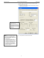
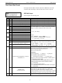
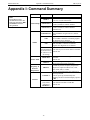
Manual revision 017
Appendix II: Commands Sent Automatically by Seasave
SBE 11plus V2
Suppress Data Word Command
Xn
Note:
If using Seasave, suppression of
data words and inclusion of NMEA
data is entered in the configuration
(.xmlcon or .con) file. The Deck
Unit sends the appropriate Xn and
Nx commands based on the
settings in the configuration file.
n= suppressed word number
(hexadecimal).
Channels can be deleted from data stream
transferred to computer with Xn.
For frequency channels, a word contains
1 channel; for A/D channels, a word
contains 2 channels. Command is useful in
reducing scan size, reducing space
required to store data.
NMEA Command
Nx
x=Y: Add Lat/Lon data to CTD data.
x=N: Do not.
Start Collecting Data Command
Gx
x=I, R, or B
Signals Deck Unit to begin putting data
into its output buffers at a rate determined
by how many scans are averaged.
x=I: Put data into IEEE-488 buffer.
x=R: Put data into RS-232C buffer.
x=B: Put data into both buffers.
User’s computer obtains this data by
exercising appropriate bus protocol.
Stop Placing Data into Buffers Command
S
Deck Unit stops putting data into buffers.
Send S when ready to stop sampling.
81
Manual revision 017
Appendix III: Functional Description and Circuitry
SBE 11plus V2
Appendix III: Functional Description
and Circuitry
Deck Unit Data Interfaces
The Deck Unit has both IEEE-488 (parallel) and RS-232C (serial) interfaces.
Data output and control commands can be sent via either interface. To
successfully transmit full rate (24 Hz) data with all channels active, set the RS232C interface to 19200 baud or use the parallel interface. With minimum data
channels active (4 words) and a reasonably fast computer (i.e., 80386
processor), 24 Hz data acquisition may be accomplished at lower baud rates.
Memory buffers at the output ports prevent data loss when the computer is
temporarily occupied by other tasks (buffer size = 20500 bytes for IEEE-488,
8000 bytes for RS-232C). The RS-232C interface outputs ASCII characters.
The modem interface provides a bi-directional serial communication link with
the CTD that is independent of the telemetry channel. This link may be used to
control a water sampler interface or to communicate with a serial device that is
cabled to the CTD.
The NMEA 0183 interface permits the Deck Unit to integrate Latitude,
Longitude, and Time data into the CTD data stream.
Data Telemetry Receiver
The telemetry waveform originates in the CTD and is transformer-coupled
onto the sea cable. In the Deck Unit, another transformer removes the
telemetry signal from the sea cable. The signal is amplified, filtered, and
converted to logic level prior to being sent to a UART and then to a microcontroller, which checks the decoded bits and activates a valid character line to
indicate successful reception of each 8-bit character. The absence of the valid
character signal, at times when it is expected, lights the Deck Unit Error LED.
Deck Unit Modem
The Deck Unit modem provides a 300-baud, full-duplex, serial communication
link with the CTD. This channel is used by the Deck Unit for water sampler
control and control of a remote serial device.
The CTD uses the setting of the most significant bit to determine what to do
with a command received from the Deck Unit:
• Characters received by the CTD with the most significant bit set (ASCII
values 128 - 255) are interpreted as commands to a water sampler. The
CTD interprets the command, encodes it in the format required by the
water sampler, and sends it to the water sampler.
• Characters received by the CTD with the most significant bit not set are
passed along unchanged to a remote serial output device.
All characters received by the CTD from the water sampler and remote serial
output device are sent to the Deck Unit. Water sampler operation does not
interfere with operation of a remote serial output device, and vice versa.
82
Manual revision 017
Appendix III: Functional Description and Circuitry
SBE 11plus V2
The Deck Unit automatically sends the following commands (as applicable)
when the user pushes the Home/Arm and Fire buttons (or fires bottles
through Seasave).
SBE 32 Carousel Commands and Replies
Commands to Carousel
#SR
#SF
#SNx
Examples:
#SN2
#SN<
Replies
6, !, 6
6, #, 6
6, -, 6
6, 49, 6
6, 72, 6
Go to home position (position #1).
Fire next position (sequential firing).
Fire position x (first position is 1).
fire position # 2
fire position # 12
At home position.
Received invalid bottle number.
Did not confirm fire.
Fired bottle # 2.
Fired bottle # 24.
G.O. 1015 Rosette Commands and Replies
Commands to CTD
#ENBL
#FIRE
Supply power to Rosette.
Remove power from Rosette, fire bottle.
Replies
#ENABLED
#CONFIRM
Ready to fire bottle.
Bottle fire confirm pulse detected.
G.O. 1016 Rosette Commands and Replies
Commands to CTD
#GH
#GOx
#GF
#GNx
Examples:
#GN2
#GN:
Replies
7, Oxf2, 7
7, Oxf4, 7
7, Oxc9, 7
7, Oxca, 7
Go to home position
Set arm offset to x, go to home position.
Fire position, move to next position.
Go to position x.
go to position # 2
go to position # 10
Positioning error, returning to home.
Positioning error, could not find home.
Ready to fire position #1 (home).
Ready to fire position #2 (home).
Miscellaneous Commands
The following commands apply to a CTD with an optional control line on the
Modem PCB. They can be used to control a device, such as the pump, wired to
the control line.
Commands to CTD
#P0
#P1
83
Control function off (line logic set low).
Control function on (line logic set high).
Manual revision 017
Appendix III: Functional Description and Circuitry
SBE 11plus V2
Deck Unit Power
The Deck Unit operates on 105 - 125 VAC or 210 - 250 VAC (50 to 60 Hz),
depending on the setting of the back panel power switch. A power supply
(Power One model HTAA-16W-A) creates +5, +12, and -12 volts DC for use
by the Deck Unit electronics and telemetry receiver. The input power line is
fused with at 2 Amp Slow-Blow fuse when operating at 120 VAC. The fuse
should be replaced with a 1 Amp Slow-Blow type for use at 240 VAC. The
Power One supply has fold-back current limiting, and is not separately fused.
Sea Cable Supply
A choke-input supply provides 250 VDC at up to 0.25 amperes to the sea
cable; a 0.5 amp fuse (located on the Deck Unit back panel) protects against
accidental shorting or overload of the sea cable.
Deck Unit Cooling
The Deck Unit has a fan in the back panel. Slots at the back panel top and
bottom allow air interchange.
Tape Recorder/VCR Interface
Note:
An 11plus V2 with jumpers set
for serial data uplink cannot
output data through the tape
recorder interface. See
Section 10: Setting Up RS-232
Serial Data Uplink.
The tape recorder interface permits use of an audio recorder or VCR for data
backup in case of computer failure, or for data recording when no computer is
available. Connect the recorder line input and line output to the Record and
Play connectors (respectively) on the Deck Unit. Set the record level to 0 db.
When playing back data, the front panel Signal Source switch must be in the
Tape position. Most high-quality cassette decks will perform well with this
system, although recording time is usually limited to 90-120 minutes due to
cassette tape capacity. Best results will be obtained with metal oxide tapes.
VCRs with super-long play capability can offer up to 6 hours of recording.
Simply use only the audio input and output on the VCR, ignoring the video.
Circuitry
WARNING!
Potentially lethal voltage levels
are maintained for 15 seconds
after removal of AC power. Turn
off the Deck Unit and remove the
AC power cord from the back
panel before attempting to
service the system. Wait at least
1 minute after power down
before working on the Deck Unit,
sea cable, CTD, etc.
Deck Unit electronics are in a rack-mount cabinet, housing two main PCBs,
two modular power supplies, a cooling fan, and front panel displays and back
panel connectors. The electronics are powered from 120 or 240 VAC. Set the
AC voltage switch (on the Deck Unit back panel) to 120 or 240 before
powering the Deck Unit.
84
Manual revision 017
Appendix III: Functional Description and Circuitry
SBE 11plus V2
Chassis Wiring
The chassis wiring diagram shows the Deck Unit modules and wiring.
Drawing 32233 shows the wiring of the Deck Unit. The required AC power
input fuse is 2 Amp Slow-Blow when set to 120 VAC units and 1 Amp SlowBlow when set to 240 VAC. There is also a 0.5 A Fast-Blow fuse in series
with the sea cable output for protection against shorts or overloads.
Power Supplies
Power for Deck Unit circuitry is supplied by a conventional open-frame linear
supply (Power One Model HTAA-16W-A; Power-One, Inc., Camarillo,
California) generating ±12 and +5 volts from the main AC supply, located at
the top left front of the chassis. Screwdriver adjustment of the output voltage
levels is possible, but not ordinarily required. The Power-One supply uses
fold-back current limiting for complete short-circuit protection. Detailed
specifications and a schematic diagram are included in this manual.
Sea Cable Supply
The Deck Unit uses a linear supply to produce the sea cable voltage 250 volts
at 0.25 amperes (reference drawing 32233). AC power is input to power
transformer T1 (primary connections are switched to work on 120 or
240 VAC) to generate approximately 275 V RMS for input to a bridge rectifier
(Motorola 100JB12L). The resulting DC voltage is regulated by series
inductor L1 and capacitor (Mallory CGS801T450V4L, 800 uF/450 volts) to
produce 250-volt output. R1 is a bleeder resistor used to stabilize the supply
output voltage and ensure supply discharge within a reasonable (15 second)
interval. Output voltage decay time constant is R1*C2 (3.2 seconds).
Receiver/Modem PCB
The receiver circuitry (drawing 33420) is installed components-downward on
the smaller PCB mounted immediately below the main (microprocessor) PCB.
The decoder circuitry is on the same PCB, as is tape recorder interface section.
Transformer T1 provides decoupled 34560 Hz sea cable telemetry signal to a
bandpass filter C9/L1 and C11/L2. Transistor pair Q2 and Q3 applies gain,
while C13 and T3 produce additional filtering. U1A is a gain stage and Q7/Q8
convert the signal to 5-volt logic level.
Shift-register U3 and X-OR U2C provide the DPSK decoding function
(U11and its associated counter circuits provide the bit-clock), with Bessel
filter (U4 and associated components) extracting the NRZ data stream.
Comparitor U5 converts the NRZ signal to full logic level. The receiver
microcontroller, U7, converts the CTD data into frequencies and voltages and
transmits the converted data 24 scans per second to the main digital PCB for
further processing. The NRZ data stream is fed to U13, where it is encoded to
DPSK format for use by analog tape recorders.
The modem circuitry (drawing 33420) utilizes a Motorola MC145443 300
Baud FSK single chip modem. Transmit frequencies are 2025 and 2225 Hz;
receive frequencies are 1070 and 1270 Hz. Transformer T2 on the Receiver
PCB couples the modem to the sea cable. U9, U10, and U11 provide filtering
for the received signal. U7 and U8 act as a buffer and line driver for the
transmitted signal.
U1 is an RS-232 to TTL level converter. U5 is a micro-controller that accepts
input from the pushbuttons on the front panel and listens to the traffic on the
modem channel. U5 sends commands to the water sampler interface and lights
the Home/Arm and Fire LEDs as appropriate.
85
Manual revision 017
Appendix III: Functional Description and Circuitry
SBE 11plus V2
Digital PCB
The main Digital PCB (drawing 32127):
1.
2.
3.
4.
5.
6.
7.
8.
Acquires full rate data from the Receiver PCB.
Acquires NMEA navigational data.
Digitizes Surface PAR voltage and merges this voltage into the CTD
data stream.
Time aligns conductivity frequencies and voltages if requested.
Averages data if requested.
Stores processed data in RAM FIFO buffers for transmission to computer
via RS-232 or IEEE-488.
Outputs raw pressure data for towed body control.
Uses a second microprocessor with EEPROM memory to output
converted CTD data in engineering units.
86
Manual revision 017
Appendix IV: Replacement Parts
SBE 11plus V2
Appendix IV: Replacement Parts
Part
Number
Part
17556
MS3106A-12S-3P
2-pin to pigtail,
10 m (33 ft)
171887
DB-9P 9-pin to
DB-9S 9-pin serial
cable, 3 m (10 ft)
171886
DB-25P 25-pin to
DB-9S 9-pin serial
cable, 3 m (10 ft)
17082
IEEE-488 cable
17015
17824
80915
801422
801429
801367
171890
801237
AC power cable
(U.S. standard)
AC power cord
(European plug)
MS3106A-12S-3P
2-pin to RMG-2FS
2-pin cable,
10 m (33 ft)
MS3106A-12S-3S
2-pin to DB-9S
9-pin NMEA
Interface test cable,
1.8 m (6 ft)
MS3106A-14S-5P
5-pin to DB-9S
9-pin cable,
1.8 m (6 ft)
MS3106A-14S-2P
4-pin to Switchcraft
EN3C5F 5-pin cable,
15 m (50 ft)
Application Description
Connects Sea Cable on Deck
Unit to slip ring
For 11plus shipped after March
2010: Connects SBE 11
Interface (RS-232) and Modem
Channel on Deck Unit to
computer COM ports
For 11plus shipped before
March 2010: Connects SBE 11
Interface (RS-232) and Modem
Channel on Deck Unit to
computer COM ports
Connects SBE 11 Interface
(IEEE-488) on Deck Unit to
parallel port on computer
Connect Deck Unit to AC
power source
Connect Deck Unit to AC
power source
Quantity
1
2
2
1
1
1
Test cable to connect Deck Unit
to CTD
1
Test cable to connect NMEA
Input on Deck Unit to computer
running NMEA simulation
program for test purposes
1
Test cable to connect Remote
Out on Deck Unit to computer
for Remote Output setup
1
Cable to connect Surface Par
Input on Deck Unit to Surface
PAR sensor with Switchcraft
connector (current connector
used by Biospherical
Instruments)
Null modem cable to connect
Serial Data Uplink on Deck
Unit to computer
DB-9P 9-pin to
DB-9S 9-pin,
3 m (10 ft)
MS3106A-14S-5P
Cable to connect
5-pin to
Remote Out on Deck Unit to
MS3106F-14S-7S
SBE 14 Remote Depth Readout
3-pin, 100 m (328 ft)
1
1
-
171888
DB-25S 25-pin to
DB-9P 9-pin
cable adapter
For use with computer with DB25 connector
-
30017
Rack mounting kit
For mounting deck unit
1
87
Manual revision 017
Appendix V: Manual Revision History
SBE 11plus V2
Appendix V: Manual Revision History
Manual
Version
001
002
11/97
01/98
003
02/00
004
09/00
005
006
02/02
05/03
Date
Description
•
•
•
•
•
•
•
•
•
•
•
•
•
•
•
•
•
•
007
02/04
•
•
008
05/04
009
03/05
010
03/07
•
•
•
•
•
•
•
•
•
011
03/08
•
•
•
•
012
09/08 •
Continued on next page
Release of firmware version 2 (11plus V2).
Add photos.
Update circuitry.
Digital firmware 5.1b: addition of NMEABaud= command.
Correct information regarding positions E and F in Data Word Front Panel Display.
Correct pressure alarm description.
Update front panel display descriptions (switch and light colors changed for water sampler
control).
Update thumbwheel descriptions (current thumbwheels 0-15; old thumbwheels 0-9 and A-F).
Rewrite.
Digital firmware 5.1f: Add new commands AutoRun= and AddNMEA=.
Add more description of serial data uplink.
Update NMEA simulation program description for new Windows software.
Correct power specification from 50/400 to 50/60 Hz.
Add information on not editing .dat file with a text editor.
Correct NMEA wiring.
Correct information on appending of NMEA data. NMEA data appended to end of scan for IEEE
only; for RS232, NMEA data output on line by itself, once/second.
Add information that GO 1015 fires sequentially only.
Update Surface PAR wiring information: Biospherical has used 3 different connectors in past,
resulting in 3 different cable drawings (32704, 31475, 32434). Most recent version uses 12345
pins instead of abcd.
Update references to Rosette Summary to Bottle Summary (corresponding to change in SBE Data
Processing).
Add information on Firing Bottles from Deck unit Front Panel: note that must have Modem
channel hooked up to PC (in addition to SBE 11 Interface hooked up to PC) for Seasave to
receive fire confirmation from Carousel and create .ros file, even though not firing bottles through
Seasave.
Add information that when 11plus deck unit has its jumpers set for Serial Uplink, tape interface
section of deck unit will not work.
Correct jumper settings in 11plus for serial data uplink.
Update information on modem interface: now standard feature instead of option.
Add information that 17plus can provide data backup while using 9plus with 11plus.
Add information that if user selects Scan time added in .con file, Seasave adds # of seconds since
Jan 1, 1970 Greenwich mean time to each scan.
Incorporate Seasave V7: no more .dat files created (.hex instead), update all descriptions of how
to setup and use Seasave.
Correct information on Modem channel PC to Deck Unit (bi-directional): 300 baud, not 19200.
Correct information on water sampler firing: setting bit high is only for GO 1015. For GO 1016
and Carousel, no bit is set; a .bl file is created.
Update schematic that shows bottom contact alarm (show bottom contact, altimeter, and/or
pressure alarm).
Correct deck unit dimensions.
Seasave: Update .con file screen capture and discussion of acquiring NMEA data: can now select
whether NMEA data is appended in Deck Unit or directly by the computer.
Seasave: Update Seasave water sampler tab dialog box (remote firing now available). Describe
ability to do mixed mode auto fire and to do auto fire on downcast.
Correct description of diagnostic NMEA commands NSR & NSI.
Add notes where NMEA is discussed, explaining that can connect NMEA directly to computer.
88
Manual revision 017
Appendix V: Manual Revision History
SBE 11plus V2
Continued from previous page
013
03/10 • Changes required for CE certification.
• New photo and drawing of back panel.
• Add statement about compatibility with Vista.
• Update software name.
• Add information about .xmlcon file.
• Add information about unsupported modem message from Carousel.
• Update SBE address.
014
11/10 • Update configuration file information related to Surface PAR sensor: Seasave 7.21a and later
sends AddSPAR= command to 11plus based on setting in configuration file, for 11plus firmware
> 5.0.
• Add information on specifying and ordering sea cable, winch, and deck gear.
• Update SBE 11 Interface and Modem channel connector cable; redesign in March 2010 changed
these to 9-pin instead of 25-pin connectors.
• Receiver PCB and Modem PCB were combined into a Receiver/Modem PCB with the redesign
changes documented in manual version 013, but the information was not updated in the manual.
Jumper position description for serial data uplink updated to correspond to new PCB.
015
08/11 • Add detail that PN 171890 cable from Serial Data Uplink connector on Deck Unit to computer is
a null modem cable.
• Add information in Troubleshooting section on correcting configuration (.con or .xmlcon) file if
scan length errors are received in Seasave or SBE Data Processing.
• Add information on manual pump control (for use with 9plus with optional manual pump
control).
016
02/13 • Add Declaration of Conformity.
• Add cable wiring drawings.
• Update software compatibility information.
• Clarify description of options in 9plus and 11plus required for serial data uplink interface.
017
02/15 • Update photos and dimensions for new deck unit housing.
• Update Seasave / SBE Data Processing configuration dialog box.
• Update language on where to find updated software on website.
• Update link to cable and winch supplier page on website.
• Remove standard and optional language related to 11plus features.
• Fix typos.
• Switch to new Sea-Bird Scientific manual cover.
89
Manual revision 017
Index
SBE 11plus V2
Index
Deck Unit
back panel · 15
dip switches · 53
front panel · 13
Declaration of Conformity · 3
Description · 9, 82
Dip switches · 53
.
.con file · 33, 44
.xmlcon file · 33, 44
A
Auxiliary sensors · 22
E
B
Editing data files · 63
Electrical symbols · 77
Back panel · 15
Baud rate · 12
Bottle firing · 54, 59, 61
F
Firing bottles · 54, 59, 61
Front panel · 13
Functional description · 82
C
Cable · 19
Cables · 16
Calibration coefficients
CDO · 46
Carousel · 53, 61
CDO · 46
calibration coefficients · 46
commands · 48
data format · 52
CE certification · 3
Circuitry · 82
Cleaning · 69
Command summary · 78
Commands · 31
automatic · 80
CDO · 48
NMEA · 36
pressure frequency and temperature · 45
Seasave · 80
summary · 78
Surface PAR · 43
Communications · 12
Configuration file · 33, 44
Converted data output · 46
CTD
configuration file · 33, 44
CTD data · 20, 31, 38
G
G.O. 1015 · 53, 61
G.O. 1016 · 53, 61
Glossary · 76
I
Installation · 19, 20
M
Maintenance · 69
Manual Pump Control · 62
Manual revision history · 88
Mounting · 19
N
NMEA · 20, 35
data formats · 41
message formats · 41
setup · 37
simulation program · 39
testing · 38
troubleshooting · 39
NMEATest · 10, 23, 39
D
Data acquisition · 59
Data format · 64
CDO · 52
Deck Unit LED · 65
engineering units · 68
IEEE-488 raw output · 66
pressure frequency and temperature · 45
raw output · 66
RS-232 raw output · 67
Surface PAR · 44
Data processing · 63
Deck gear · 19
O
Operating system · 59
P
PAR · 21
Parts
replacement · 87
Power · 22
Pressure frequency and temperature · 45
Processing data · 63
PROG11V2 · 46
Pump Control · 62
90
Manual revision 017
Index
SBE 11plus V2
R
T
Real-time data acquisition · 59
Remote output · 21, 45
Replacement parts · 87
Revision history · 88
Rosette · 53, 61
Routine maintenance · 69
RS-232 uplink · 21
Testing
NMEA · 38
Troubleshooting · 70
NMEA · 39
U
Unpacking SBE 11plus V2 · 8
S
V
Safety symbols · 77
SBE 14 · 46
SBE 32 · 53, 61
SBE 46 · 46
SBE Data Processing · 10, 23, 28, 68
Sea cable · 19, 20
Seasave · 10, 23, 26, 33, 36, 38, 44, 54, 59, 68, 80
Seasoft · 10, 23
Seaterm · 10, 23, 24, 30, 31, 36, 37, 43, 45, 47, 48, 78
Serial cata uplink · 21
Serial data output instrument · 56
Setup · 30
CDO · 47
general · 30
general commands · 31
NMEA · 37
serial data output instrument · 56
Surface PAR · 43
Simulation program · 39
Slip ring · 19
Software · 10, 23
installation · 23
Specifications · 11
Surface PAR · 21, 43
data format · 44
Surface PAR setup · 43
System communications · 12
System description · 9
System operation · 59
System setup · 30
System wiring · 20
Versions · 88
W
Water sampler · 20, 22, 53
dip switches · 53
Winch · 19
Wiring · 16, 20
91