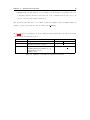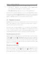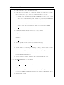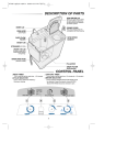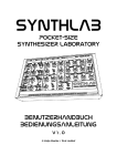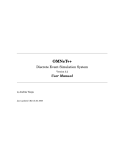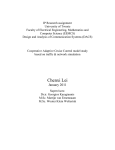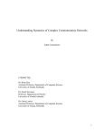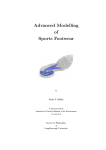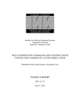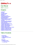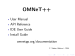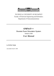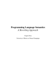
1
NETA: A NETwork Attacks Framework
Architecture and Usage
NESG - Network Engineering & Security Group
University of Granada, Spain
Generated on October 8, 2013
Copyright (C) 2013 developed by NESG (Network Engineering and Security Group) members:
• Gabriel Maciá Fernández ([email protected])
• Leovigildo Sánchez Casado ([email protected])
• Rafael A. Rodrı́guez Gómez ([email protected])
• Roberto Magán Carrión ([email protected])
• Pedro Garcı́a Teodoro ([email protected])
• José Camacho Páez ([email protected])
• Jesús E. Dı́az Verdejo ([email protected])
This work is licensed under a Creative Commons Attribution-ShareAlike 3.0 Unported License.
Contents
Contents . . . . . . . . . . . . . . . . . . . . . . . . . . . . . . . . . . . . . . . . . . .
1
1 Introduction . . . . . . . . . . . . . . . . . . . . . . . . . . . . . . . . . . . . . . .
2
1.1
What is NETA Framework? . . . . . . . . . . . . . . . . . . . . . . . . . . . . . .
2
1.2
About the Documentation . . . . . . . . . . . . . . . . . . . . . . . . . . . . . . .
2
2 Architecture Overview . . . . . . . . . . . . . . . . . . . . . . . . . . . . . . . . .
3
2.1
Design Principles . . . . . . . . . . . . . . . . . . . . . . . . . . . . . . . . . . . .
3
2.2
Architecture . . . . . . . . . . . . . . . . . . . . . . . . . . . . . . . . . . . . . . .
4
2.3
Folders Structure . . . . . . . . . . . . . . . . . . . . . . . . . . . . . . . . . . . .
7
3 Implemented Attacks
. . . . . . . . . . . . . . . . . . . . . . . . . . . . . . . . .
8
3.1
IP Dropping Attack . . . . . . . . . . . . . . . . . . . . . . . . . . . . . . . . . .
8
3.2
IP Delay Attack . . . . . . . . . . . . . . . . . . . . . . . . . . . . . . . . . . . .
9
3.3
Sinkhole Attack . . . . . . . . . . . . . . . . . . . . . . . . . . . . . . . . . . . . .
9
4 Using the Framework
. . . . . . . . . . . . . . . . . . . . . . . . . . . . . . . . . 11
4.1
Installation of the NETA Framework . . . . . . . . . . . . . . . . . . . . . . . . .
11
4.2
Simulation Scenarios . . . . . . . . . . . . . . . . . . . . . . . . . . . . . . . . . .
12
4.3
Create Your Own Simulation . . . . . . . . . . . . . . . . . . . . . . . . . . . . .
14
5 Writing Code for NETA . . . . . . . . . . . . . . . . . . . . . . . . . . . . . . . . 16
5.1
Implementing New Attacks . . . . . . . . . . . . . . . . . . . . . . . . . . . . . .
16
5.2
Implementing Simulation Scenarios . . . . . . . . . . . . . . . . . . . . . . . . . .
19
Bibliography . . . . . . . . . . . . . . . . . . . . . . . . . . . . . . . . . . . . . . . . . 20
1
Chapter 1
Introduction
1.1
What is NETA Framework?
NETA is a framework for the simulation of communication networks attacks. It is built on top
of the INET framework and the OMNET++ simulator. NETA is intended to become an useful
framework for researchers focused on the network security field. Its flexible design is appropriate for the implementation and evaluation of many types of attacks, doing it accurate for the
benchmarking of current defense solutions under same testing conditions or for the development
of new defense techniques.
NETA is based on INET framework, which provides precise implementations of many different
protocols in the computer networking protocol stack, as well as models for mobility, battery
consumption, channel errors, etc.
1.2
About the Documentation
The rest of this document is organized as follows. The general architecture of the NETA framework is presented in Chapter 2, where the main components and the design rules are explained.
In Chapter 3, we describe the implemented attacks, specifying (i ) its behavior, (ii ) the parameters used to manage them, and (iii ) the modified modules related to them. Chapter 4 explains
how to use the framework: from its installation to the creation of simple simulation scenarios.
Finally, Chapter 5 exposes, step by step, the process to implement a new attack by following the
design rules of the present framework.
2
Chapter 2
Architecture Overview
This chapter describes the architecture of the NETA framework. NETA is based on the same
idea as OMNeT++, i.e., modules that communicate by message passing.
The general idea is to develop models in OMNET++ implemented as new nodes which can strike
attacks, attacker nodes. In order to do this, the attacks are managed by the so-called attack
controllers. These controllers manage one or more modules of a NETA framework attack node
by sending control messages. These messages are sent from attack controllers to specific modules
that implement a modified behavior for the attack. They are called hacked modules hereafter.
For implementing this modified behavior, these hacked modules are inherited or replicated from
INET modules and conveniently modified to obey the orders of attack controllers.
2.1
Design Principles
The design principles of the present framework follow two main rules:
Rule 1 Any base framework we use must not be modified, e.g., when using INET modules, they
should remain as the original one.
This rule is intended to facilitate the compatibility with future releases of INET and other implementations. To accomplish this rule we just import the last version of INET framework and
we do not carry out any modification on it.
Rule 2 To modify the least possible the original code of the hacked modules.
3
Chapter 2. Architecture Overview
4
Obviously, in order to implement the desired attacks, it is necessary to modify the behaviour of
the modules that will become hacked modules. However, this rule is intended to minimize these
modifications as much as possible.
To accomplish this rule we propose the following two options depending on the original code:
1. Inheritance and method overriding. If the method which needs to be modified in the original
class is defined as virtual, a new class which inherits from the father is created in NETA
framework structure. Next, the desired methods are overridden to include the attack’s
behavior.
2. Code replication. If the method which needs to be modified is NOT declared as virtual,
the original class is replicated in NETA framework structure and then the desired methods
are modified to include attack’s behavior.
If possible, the first option is preferred, inheritance and method overriding, because is the least
invasive option, and therefore, the best option to accomplish the second rule.
2.2
Architecture
In the following we describe the main components of an attack in our framework: (i ) attack
controllers, (ii ) control messages, and (iii ) hacked modules.
Attack Controllers
The attack controllers are the modules which control the execution of the attack. They can be
directly configured in the .ini file and they have the following properties:
- attackType (string): name used to identify the attack. It should correspond with the tag
located in the NA <attackName>.ned file.
- active (bool): it indicates whether the attack is active in the simulation or not.
- startTime (double): the time at which the attack starts in the simulation.
- endTime (double): the time at which the attack ceases.
- Attack specific parameters: different configuration parameters depending on the specific attack functionalities.
Chapter 2. Architecture Overview
5
The processes carried out by an attack controller for attack Ai in an attacker node can be
summarized as:
1. To obtain the different hacked modules involved in the execution of attack Ai .
2. To activate those hacked modules in the attack node by sending, at start time, activation
messages which can contain configuration information.
3. To deactivate the hacked modules in the attack node by sending a deactivation message at
end time.
Control Messages
These messages are sent from attack controllers to the hacked modules involved in the attack
execution. They transmit the information necessary for the activation and deactivation of the
attacks. Additionally, these messages contain configuration information needed for the execution
of the attacks.
It is important to remark that control messages are sent directly to a hacked module. This is the
best option to accomplish the Rule 2 of our design principles: “To minimize the modifications to
the original code of hacked modules”.
Hacked Modules
These are the modules whose behavior is modified in order to strike an attack. For example, a
packet dropping attack usually requires a modification in the module that makes IP forwarding.
Therefore, the implementation of a dropping attack implies the modification of the NETA IPv4
module, which behaves as a hacked module.
Note that there exists only one hacked module per modified module, and not a hacked module
for every attack implementation. If two different attacks need to modify the same module, there
will only exist one hacked module for them. For instance, as it will be shown, both delay and
dropping attacks are related to the IPv4 module. Thus, a single hacked IPv4 module is needed
for the implementation of the two attacks. This design is aimed to improve the flexibility of
the framework, allowing the execution of more than one attack simultaneously, e.g., delay and
dropping attacks can be triggered by the same node only by including their attack controllers.
Chapter 2. Architecture Overview
6
Hacked modules must implement the handleMessageFromAttackController(cMessage ∗ msg)
method, inherited from its father. This method receives a control message from the attack controller which contains the necessary information to configure the specific attack.
Fig. 2.1 shows the differences between a normal (original) node and an attacker node. The normal
node is composed of simple and compound modules communicating among them. The attacker
node is composed of the same number of modules but now controller modules are added. In
addition, some of the modules are replaced by hacked modules, in order to allow the execution
of attack behaviours when triggered by attack controllers.
Figure 2.1: Scheme comparison between an original node and its attacker in NETA framework.
Fig. 2.2 shows an example of the modules which compose a normal node (AdhocHost) and
its corresponding attacker node (NA AttackerAdhocHost).
(a) Modules of AdhocHost node
(b) Modules of NA AttackerAdhocHost node
Figure 2.2: Real comparison between an original AdhocHost and NA AttackerAdhocHost.
Chapter 2. Architecture Overview
7
Thus, the creation of an attacker node can be summarized as: (i ) add to the associated .ned file
the controllers related to the attacks to be executed, (ii ) create the associated control messages
and, (iii ) substitute the modules needed by these attacks controllers for corresponding hacked
modules. This process will be further explained in Section 5.1.
2.3
Folders Structure
The folders of NETA framework have a specific structure which is described in the following. It
must be noted that only the specific folders of this framework are mentioned, excluding those in
common with INET:
netattacks/doc/
This folder contains the documentation of the NETA framework, automatically generated
by Doxygen. Click on the index.html file to access the whole documentation.
netattacks/resources/
This folder contains additional resources required for NETA framework to work properly.
Specifically, it includes different patches that must be applied.
netattacks/simulations/
. simpleAttackScenarios: this folder contains the sample simulation scenarios provided to
demonstrate the performance of the implemented attacks.
netattacks/src/
. attacks: in this folder are located the attack controllers and the control messages used by
these controllers to communicate with the associated hacked modules.
. common: this folder contains different utilities, like the log module, etc.
. hackedmodules: here they are the modified modules whose behavior triggers the implemented attacks, i.e., the hacked modules.
. nodes: in this folder can be found the new hosts which are created as slight modifications
of the existing ones in INET framework. They have their corresponding hacked modules,
as shown in Fig. 2.2.
Chapter 3
Implemented Attacks
This chapter exposes the attacks implemented for the NETA framework. In the subsequent
sections, for every implemented attack we describe: (i ) the behavior of the attack, (ii ) the parameters which can be modified to configure the attack, and (iii ) the hacked modules related to
the attack.
It must be noted that every implemented attack has the following common parameters which
were explained in Section 2.2: attackType, active, startTime and endTime.
3.1
IP Dropping Attack
In the IP dropping attack, nodes exhibiting this behavior intentionally drop, with a certain
probability, received IP data packets instead of forwarding them, disrupting the normal network
operation. Depending on the application, it can turn the network much slower due to the
existence of retransmissions, make the nodes waste much more energy resources, etc. The main
parameter of our implementation of the dropping attack is:
• droppingAttackProbability (double): the probability of dropping a packet, defined between 0 and 1. By default, it is set to 0 which makes the attacker node to behave normally
(no dropping at all).
The original module that has to be modified to strike the dropping attack is IPv4. With our
naming convention the hacked module is renamed as NA IPv4.
8
Chapter 3. Implemented Attacks
3.2
9
IP Delay Attack
In this attack, a malicious node delays IP data packets for a certain amount of time. This
can affect different QoS parameters (end-to-end delay, jitter, etc.), resulting in a poor network
performance. The list of parameters in our implementation of the delay attack is:
• delayAttackProbability (double): the probability of delaying a data packet, defined
between 0 and 1. By default, it is set to 0 which implies a normal behavior for the attacker
node (no extra delay for any packet).
• delayAttackValue (double): the specific delay time applied to the packet. Note that this
parameter could be specified by a statistical distribution. For this reason, it is defined
as volatile, i.e., it is modified every time it is accessed. By default, it follows a normal
distribution with mean 1 second and standard deviation of 0.1 seconds.
The original module that has to be modified to strike the delay attack is also IPv4. Thus, the
hacked module is the same as before, NA IPv4.
3.3
Sinkhole Attack
In a sinkhole attack, a malicious node sends fake routing information, claiming that it has an
optimum route and causing other nodes to route data packets through itself. Here, the attacker
forge routing replies (RREP) to attract traffic. The list of parameters of sinkhole attack is:
• sinkholeAttackProbability (double): the probability of answering a RREQ message with
a fake route reply (RREP), defined between 0 and 1. By default it is set to 0 which implies
the normal behavior of AODV protocol.
• sinkOnlyWhenRouteInTable (bool): if set to true, the sinkhole only sends fake RREP to
requests for those that the attacker node has a valid route, i.e., routes existing in its routing
table. Otherwise (false value), the node sends fake RREP to any RREQ message arriving, even
if it does not know a valid route.
• seqnoAdded (double): the fake sequence number generated by the attacker node. It is
added to the sequence number observed in the request. It can be different each time, if it
is specified as an statistical distribution. By default, it follows a uniform distribution with
values between 20 and 30.
Chapter 3. Implemented Attacks
10
• numHops (int): the fake number of hops returned by the attacker. By default, it is set to
1, indicating that the attacker reaches the end of the communication in only one hop. It
can also follow a given statistic distribution.
The original module that has to be modified to strike the sinkhole attack is AODVUU. With our
naming convention the hacked module is renamed as NA AODVUU.
Table 3.1 shows a brief summary about the different attacks implemented, as well as its parameters and hacked modules associated.
Attack Name
IP Dropping
IP Delay
Sinkhole
Parameters
droppingAttackProbability (double)
delayAttackProbability (double)
delayAttackValue (double)
sinkholeAttackProbability (double)
sinkOnlyWhenRouteInTable (bool)
seqnoAdded (double)
numHops (int)
Hacked Modules
IPv4 → NA IPv4
IPv4 → NA IPv4
AODVUU → NA AODVUU
Table 3.1: Summary of the different implemented attacks.
Chapter 4
Using the Framework
4.1
Installation of the NETA Framework
NETA framework is built on top of OMNeT++ [1], an object-oriented, modular, discrete event
library, primarily for building network simulators. Besides, NETA is based on INET framework.
In order to install NETA, you must follow the instructions presented below:
1. Install OMNeT++: download the OMNeT++ source code from http://omnetpp.org.
Make sure you select your platform-specific archive. Copy the OMNeT++ archive to the
directory where you want to install it and extract it. More precise details about the
OMNeT++ installation process, as prerequisites, environment variables and so on, can be
found in the Install Guide [2].
2. Import INET 2.1.0: download INET 2.1.0 from http://inet.omnetpp.org/ [3]. Import it as a new project into your workspace (File > Import > General > Existing
Projects into Workspace) and choose the option Select archive file.
3. Fix the INET bug 632: copy and override the ManetRoutingBase.cc file located into
the NETA framework folder ‘resources/patch/INET 21/’, to the folder located into the
INET project previously imported ‘/inet/src/networklayer/manetrouting/base/’.
4. Build INET project: right-click on the project present in the Workspace and select
Build Project.
5. Import NETA framework: download the last version of the NETA framework from
http://nesg.ugr.es/ [4]. Import it proceeding in a similar way to the process followed
with INET.
11
Chapter 4. Using the Framework
12
6. Reference INET framework: make sure that NETA has INET project as project reference (Project > Properties > Project References). Also, the ‘MANET Routing’
project feature must be selected (Project > Project Features).
7. Build NETA framework: right-click on the project and select Build Project.
After this process we extremely recommend you to execute one of the simple simulation scenarios
located under the ‘simulations/SimpleAttackScenarios’ folder in order to make sure that
everything is working correctly. NETA framework has been tested with the indicated versions of
OMNeT++ and INET, the last stable versions when this document was written.
4.2
Simulation Scenarios
The NETA framework provides a group of sample scenarios: simpleAttackScenarios with a clear
purpose. These simulations are focused on proving the proper attack behavior, as well as on
showing the attack capacities in a simple scenario.
In the same way that occurs with any OMNeT++ project, the parameters control the simulation
execution. Its value can be assigned in either the NED files or the configuration file (.ini) and
are used to customize the simulation behavior. There exist three simulation scenarios one for
each implemented attack. In the following we briefly describe their main characteristics.
SimpleDroppingAttackScenario
This scenario is intended to show how a dropper behaves. The scenario is composed of 3 nodes:
2 normal NA AdhocHost and 1 NA AttackerAdhocHost. They are placed in a line configuration,
being the attacker node in the middle. The attack-specific parameters make the attack to start
dropping IP data packets at 0 s and to stop dropping at 20 s. Besides, the dropping probability
is set to 0.5, i.e., the attacker drops half of the packets going through it. A screenshot of this
simulation can be seen in Fig. 4.1.
SimpleDelayAttackScenario
This scenario shows how the delay attack works. As in the previous scenario, there are 3 nodes
placed in a line configuration: 2 normal NA AdhocHost and 1 NA AttackerAdhocHost, being the
latter located in the middle. The attack-specific parameters make the attack to start delaying
IP data packets at 0 s and to stop dropping at 20 s. Besides, the delaying probability is set to
Chapter 4. Using the Framework
13
Figure 4.1: Screenshot of simple dropping attack scenario.
1 and the delay time follows a normal distribution, with mean 0.02 s and standard deviation of
0.001 s, i.e., the attacker delays every packet going through it approximately 0.02 s.
SimpleSinkholeAttackScenario
This folder includes two different scenarios which demonstrate how the sinkhole attack works
under two circumstances: whether the attacker knows the route to the destination or not
(SimpleSinkholeRoute and SimpleSinkholeNoRoute respectively). In both scenarios the sinkhole node fakes the sequence number by adding a value between 50 and 60, and fakes the number
of hops to 1.
Figure 4.2: Screenshot of SimpleSinkholeRoute attack scenario.
In the SimpleSinkholeRoute scenario (Fig. 4.2) there are 5 nodes: 4 normal NA AdhocHost and
1 NA AttackerAdhocHost. First, nodeA communicates with nodeD through the attacker between 0 and 1 s. Some time later, when the attacker already knows the route to nodeD, nodeB
Chapter 4. Using the Framework
14
Figure 4.3: Screenshot of SimpleSinkholeNoRoute attack scenario.
also requests communication with nodeD. Even though nodeC knows a one-hop route, nodeB will
choose the attacker as next hop, because of its fake reply.
Fig. 4.3 shows the SimpleSinkholeNoRoute scenario, also with 4 NA AdhocHost nodes and 1
NA AttackerAdhocHost. Here, nodeA tries to communicate with nodeD through nodeB. However
the attacker sends a fake reply even though it does not know the route to the destination and
therefore it is choosed as next hop by nodeA.
4.3
Create Your Own Simulation
If you want to implement your own simulation scenario you should follow similarly to any new
OMNeT++ simulation:
1. NED file: create a NED file containing the network components, i.e., normal and
attacker nodes, network configurator, etc.
2. Configuration file (.ini): specify in this file the parameters of your simulation.
Chapter 4. Using the Framework
15
3. Output folder: we recommend you to locate the simulation in a new folder inside
netattacks/simulations.
To analyze the obtained results from the simulations you can use the OMNeT++ IDE. This IDE
provides a rich environment for analyzing the outputs of simulations. Output files are plain text
files which make easy to process them with programming tools like Python, Matlab and Perl,
among others.
Finally, it is possible that you need to use new attacks that are not yet implemented. For these
situations, in Section 5.1 we deeply describe the process for implementing a new attack from
scratch, following the design principles of this framework.
Chapter 5
Writing Code for NETA
5.1
Implementing New Attacks
This guide briefly presents the different steps to be followed in order to implement a new attack
in the NETA Framework. As a naming convention, all the names for files and classes start by
the prefix NA .
Assuming that we want to implement an attack called example, the steps which must be followed
are described below.
Attack Controllers: src/attacks/controllers/
1. Create a new folder /exampleAttack and inside it create the class NA ExampleAttack
by creating the associated files (.ned, .h and .cc).
2. In the NA Attack.ned file, add the new attack in the attackType enum list.
3. Modify NA ExampleAttack.ned conveniently:
• Inherit the module from the NA Attack module:
simple NA ExampleAttack extends NA Attack
• Add the tag:
@class (NA ExampleAttack)
• Set the attackType parameter to the name of the attack:
attackType = "example"
16
Chapter 5. Writing Code for NETA
17
• Add the attack-specific parameters to configure the attack from the .ini files.
4. Modify NA ExampleAttack.h conveniently:
• Inherit the new class from NA Attack:
class NA ExampleAttack:
public NA Attack {
• Add the method:
cMessage ∗ generateAttackMessage(const char∗ msg)
5. Modify NA ExampleAttack.cc conveniently:
• Add the statement:
Define Module (NA ExampleAttack);
• Implement, as done in NA DroppingAttack.cc, the method:
cMessage ∗ generateAttackMessage(const char∗ msg)
including the proper NA ExampleAttackMessage m message.
Control Messages: src/attacks/controlmessages/
1. Create a new folder /exampleAttack and inside it create the activation/deactivation
message NA ExampleMessage.msg.
2. Modify NA ExampleMessage.msg to include the attack-specific parameters.
3. After building the project, a new class NA ExampleMessage m (.h and .cc) is automatically generated.
Hacked Modules: src/hackedmodules/
Every attack implementation needs a preliminary phase of study in order to identify which
modules should be modified for the considered attack.
1. Identify those INET modules to be modified. Let’s call them base modules.
2. Check, for every base module, if there is a hacked module already defined, i.e., another
attack’s implementation is already using these module:
Chapter 5. Writing Code for NETA
18
• If YES: take the code for that hacked module.
• If NO: study if it is possible to override the original code. Check if the methods
that you need to modify are defined as virtual in the base module.
– If YES: create an inherited class NA HackedModule from the base modules
and locate the associated files (.ned, .h and .cc) under src/hackedModules,
creating the same directories structure as the base module has in INET.
– If NO: Make a copy of the base module files under src/hackedModules, creating the same directories structure as the base module has in INET.
3. Modify NA HackedModule.ned conveniently:
• If the hacked module inherits from a base module, extend:
simple NA HackedModule extends BaseModule
• Add the tag:
@example
4. Modify NA HackedModule.h conveniently:
• Add the #include for the activation/deactivation message:
#include ‘‘NA ExampleMessage m’’
• Add the method for handling the messages coming from the attack controller:
void handleMessageFromAttackController(cMessage ∗ msg)
• Add the flag for controling the attack execution:
bool exampleAttackIsActive
• Add the necessary variables and methods for implementing the attack.
5. Modify NA HackedModule.cc conveniently:
• Add the statement:
Define Module (NA HackedModule)
• Implement the method:
void handleMessageFromAttackController(cMessage ∗ msg)
Don’t forget the Enter Method() statement (see example in NA IPv4 module).
• Implement the attack.
Chapter 5. Writing Code for NETA
5.2
19
Implementing Simulation Scenarios
To create an example simulation for the attack you should follow these steps:
1. Modify the attacker node:
• Insert the exampleAttack controller in the NA AttackerAdhocHost node located
in src/nodes.
• Substitute the base modules in the NA AttackerAdhocHost node by the corresponding hacked modules.
2. Modify the simulation environment:
• Create a new folder /SimpleExampleAttackScenario and locate it in the folder
/simulations/simpleAttackScenarios. Inside it create a new simulation example to include your attack.
Don’t forget to clearly comment the new section for the configuration of the
exampleAttack.
Bibliography
[1] OMNeT++ User Manual, v. 4.3. http://www.omnetpp.org/doc/omnetpp/Manual.pdf. [Online; accessed June 2013].
[2] OMNeT++ Installation Guide, v. 4.3. http://omnetpp.org/doc/omnetpp/InstallGuide.pdf.
[Online; accessed June 2013].
[3] Inet 2.1.0 for OMNeT++ 4.2/4.3. http://inet.omnetpp.org/index.php?n=Main.Download.
[Online; accessed June 2013].
[4] NETA Framework, v. 1.0.0. http://nesg.ugr.es/index.php/en/neta. [Online; accessed June
2013].
20