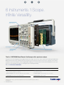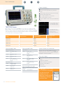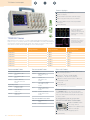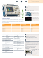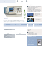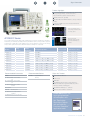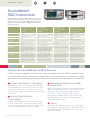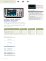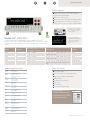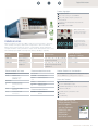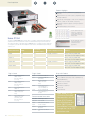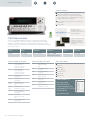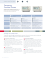
1
Bench Products Catalog 2014, Volume 2 2014 Bench Products Test & Measurement Solutions 6 Instruments.1 Scope. Infinite Versatility. Digital Voltmeter Protocol Analyzer Logic Analyzer Arbitrary/Function Generator Spectrum Analyzer Oscilloscope The 6-in-1 MDO3000 Mixed Domain Oscilloscope with a spectrum analyzer. Designs have evolved, integrating analog, digital and RF technologies. Now, it’s the oscilloscope’s turn. Introducing the MDO3000 Mixed Domain Oscilloscope. Featuring a spectrum analyzer, function generator and more, it’s the only scope that comes with the instruments you use most, built-in. It’s also upgradeable, enabling you to add instruments and increase bandwidth as your needs grow. So you get unlimited versatility at a starting price that’s anything but limiting. Win one at tek.com/oneisthenewsix 6 Advanced Instruments Built In § Oscilloscope: 100 MHz-1 GHz models, 2 or 4 channels, § Arbitrary/Function Generator: 50 MHz, 13 standard § Spectrum Analyzer: 9 kHz-3 GHz with 3 GHz wide capture bandwidth § Protocol Analyzer: Serial data trigger, decode and analysis § Logic Analyzer: 16 channels, 121 ps timing resolution § Digital Voltmeter: 4-digits resolution • 5 GS/s sample rate, 10 Mpoint record length • plus arbitrary waveforms *Starting price includes an oscilloscope, spectrum analyzer and digital voltmeter. Other instruments and bandwidth may be added for additional cost. © 2014 Tektronix, Inc. 2 www.tektronix.com Table of Contents New Products MDO3000 Mixed Domain Oscilloscope 6 Advanced Instruments in One Designs have evolved, integrating analog, digital and RF technologies. Now, it’s the oscilloscope’s turn. Featuring a spectrum analyzer, function generator and more, it’s the only scope that comes with the instruments you use most, built-in. It’s also upgradeable, enabling you to add instruments and increase bandwidth as your needs grow. So you get unlimited versatility at a starting price that’s anything but limiting. TBS1000B/TBS1000B-EDU The TBS1000B and TBS1000B-EDU are full featured instruments in a class all their own. Whether you’re looking for an oscilloscope that’s been specifically designed for teaching labs or one with extensive monitoring and analysis capability, the TBS Series of instruments are an excellent choice to handle everyday test challenges. PA1000 Power Analyzer The PA1000 measures power, energy and harmonics of power supplies and any single-phase product connected to the AC line. Best in class accuracy and connectivity make the PA1000 the ideal tool for proving energy efficient designs. Model 2450 SourceMeter® SMU Instrument with Graphical Touchscreen Offers the capabilities of analyzers, curve tracers, and I-V systems at a fraction of their cost. Source and measure voltage, current, and resistance with one tightly-coupled instrument. Capacitive touchscreen technology lets you get more done in less time. It’s a whole new experience in DC sourcemeasure testing. For an in-depth look at all of our products, including demos and 360-degree product explorers, please visit www.tektronix.com. All information on www.tektronix.com supersedes all other information. Table of Contents 4-9 Oscilloscope Selection Guide Mixed Signal and Mixed Domain 10 MSO/DPO2000B Series 11 MDO3000 Series 12 MDO4000B Series 13 MSO/DPO4000B Series Advanced Signal Analysis 14 MSO/DPO5000B Series 15 DPO7000C Series Basic 17 TBS1000B-EDU Series 18 TBS1000B Series 19 TBS1000 Series Battery Powered and Handheld 20 THS3000 Series 21 TPS2000B Series TDS 22 TDS2000C Series 23 TDS3000C Series 24 Probes and Accessories 25 Signal Generator Selection Guide 26AFG2000 27 AFG3000C Series 28SourceMeter® Selection Guide 9-30 Model 2450 2 31 2400 Series 32 2600B Series 33 2650A Series 34 Power Analyzer Selection Guide 35 PA1000 Series 36 PA4000 Series 37 38 39 40 41 Digital Multimeters Selection Guide Keithley Models 2000, 2100, 2110 Keithley Models 2001, 2002, 2010 Tektronix DMM4020 Tektronix DMM4040/4050 42 Data Acquisition Selection Guide 43 Series 2700 44 Series 3700A 45 Low-Level Instrument Selection Guide 46 2182A Nanovoltmeter 47 6220 / 6221 Current Sources 48 6485, 6487 Picoammeters, 6482 Picoammeter & Voltage Source 49 6514 / 6517B / 6430 Electrometers 50 51 52 53 54 55 56 57 Power Supplies Selection Guide PWS2000 Series PWS4000 Series 2200 Programmable Single Channel DC Power Supplies with Remote Sensing 2220/2230 Programmable Multiple Channel DC Power Supplies with Remote Sensing 2290 High Voltage Power Supplies 2300 Portable Device Battery/Charger Simulators 2300 High Speed Power Supplies 58 Frequency Counter/Timers Selection Guide 59 FCA3000/3100 Series 60 MCA3000 Series 61 RF Power Meters Selection Guide 62 PSM3000, 4000 and 5000 Series 63-64 Service Solutions www.tektronix.com 3 Choosing Your Oscilloscope Oscilloscopes Oscilloscope Selection Guides, Pages 5 - 7 Choosing Your Oscilloscope Tektronix offers oscilloscopes for many different applications and uses. To help you choose the right scope for your needs, the most common criteria for selecting a scope are listed below, along with helpful tips for determining your requirements. 1 Bandwidth 3 Record Length All oscilloscopes have a low-pass frequency response that rolls off at higher frequencies. Oscilloscope bandwidth is specified as being the frequency at which a sinusoidal input signal is attenuated to 70.7% of the signal’s true amplitude – the -3 dB point. Your oscilloscope must have sufficient bandwidth to capture all relevant frequency components of your signal. If you regularly work with digital signals, it may be easier to consider bandwidth by comparing signal and oscilloscope rise time specifications. Use an oscilloscope with a rise time specification five times faster than your signal rise time to keep error below 2%. Record length is the number of samples the oscilloscope can digitize and store in a single acquisition. Since an oscilloscope can store only a limited number of samples, the waveform duration – or length of “time” captured – will be inversely proportional to the oscilloscope’s sample rate. A longer record length enables a longer time window to be captured with high resolution. Rule: Bandwidth > 5 X Highest Signal Frequency Amplitude (%) 4 Digital Channels and Spectrum Analyzer Input Today’s oscilloscopes offer more than just analog channels for system-level troubleshooting of complex designs. 100 If you need to analyze a parallel bus or multiple serial buses, the Tektronix MSO Series of mixed signal oscilloscopes and MDO Series of mixed domain oscilloscopes offer 16 digital channels and up to 4 analog channels for analyzing multiple signals at once. If you are working with RF signals, the Tektronix MDO Series of mixed domain oscilloscopes offers a built-in spectrum analyzer for time-correlated analysis of analog, digital and RF signals. 85 70.7 0.1 0.5 1.0 Frequency (GHz) Figure 1: Typical frequency response curve for a general purpose oscilloscope 2 Sample Rate The faster an oscilloscope samples, the greater the resolution and detail of the displayed waveform, and the less likely that critical information or events will be lost. Tektronix recommends at least 5X oversampling to ensure signal details are captured and to avoid aliasing. Rule: Sample Rate > 5 x (Highest Frequency Component) 4 Rule: Captured Time = (Record Length) / (Sample Rate) www.tektronix.com 5 Features and Analysis Capability Tektronix oscilloscopes offer a range of features and analysis capabilities. When choosing your scope, you should review available triggers, waveform search tools, automated measurements, and analysis packages such as serial bus analysis, jitter and power analysis to ensure they meet your needs. Oscilloscopes Selection Advanced Signal Analysis Oscilloscopes MSO/DPO5000B DPO7000C Series Channels 4 analog channels; 16 digital channels (MSO5000B) 4 analog channels Bandwidth 350 MHz to 2 GHz 500 MHz to 3.5 GHz Spectrum Analyzer Frequency Range -- -- Sample Rate 5 GS/s to 10 GS/s (analog); 60.6 ps (16.5 GS/s) MagniVu™ (digital) 10 GS/s to 40 GS/s Max Record Length Up to 250 Mpoints Up to 500 Mpoints Trigger Types Edge, Sequence, Logic, Pulse Width, Glitch, Runt, Timeout, Transition, Set-up and Hold, Rise/Fall Time, Video, I2C*, SPI*, USB (Low, Full, High)*, RS-232/422/485/UART*, Parallel (MSO5000B), Visual Trigger Pinpoint™ Triggering, Edge, Glitch, Pulse Width, Runt, Time-out, Transition. Setup/Hold, Pattern, State, Window, Trigger Delay (by Time and by Event), I2C*, SPI*, USB (Low, Full)*, RS-232/422/485/ UART*, Visual Trigger *Optional *Optional Optional Serial Bus Decode and Analysis SR-AERO: MIL-STD 1553 SR-AUTO: CAN/LIN/FlexRay SR-COMP: RS-232/422/485/UART SR-DPHY: MIPI D-PHY SR-EMBD: I2C, SPI SR-ENET: 10/100Base-T Ethernet SR-USB: USB VNM: CAN, LIN SR-AERO: MIL-STD 1553 SR-AUTO: CAN/LIN/FlexRay SR-COMP: RS-232/422/485/UART SR-DPHY: MIPI D-PHY SR-EMBD: I2C, SPI SR-ENET: 10/100Base-T Ethernet SR-PCIE: PCI Express SR-USB: USB LSA: CAN, LIN Connectivity USB Host (x6), USB Device, LAN (10/100/1000 Base-T Ethernet, LXI Class C Compliant), Video Out, GPIB* USB Host (x5), LAN (10/100/1000 Base-T Ethernet, LXI Class C Compliant), GPIB, eSATA, DVI Additional Resources *Optional Waveform Math and Analysis 53 Automated Measurements, Waveform and Screen Cursors, Arithmetic and Advanced Waveform Math, FFT, Measurement Statistics, Waveform Histograms, Waveform Limit Testing Optional: BRR: BroadR-Reach Compliance Test; DDRA: DDR Memory Bus Analysis; DJA: DPOJET Advanced Jitter and Eye Diagram Analysis; ET3: Ethernet Compliance Test Solution; MTM: Mask Testing; PWR: Power Analysis; SignalVu Vector Signal Analysis; USB: USB Compliance Test Solution; MOST: MOST 50/150 Compliance Test Solution; HSIC: HSIC Electrical Validation; USBPWR: USB Power Adapter/ EPS Compliance Automated Test Solution 53 Automated Measurements, Waveform and Screen Cursors, Arithmetic and Advanced Waveform Math, FFT, Measurement Statistics, Waveform Histograms, Waveform Limit Testing Optional: BRR: BroadR-Reach Compliance Test; DDRA: DDR Memory Bus Analysis; DJA: DPOJET Advanced Jitter and Eye Diagram Analysis; D-PHY: MIPI D-PHY Essentials; ET3: Ethernet Compliance Test Solution; MTM: Mask Testing; PWR: Power Analysis; SignalVu Vector Signal Analysis; USB: USB Compliance Test Solution; MOST: MOST 50/150 Compliance Test Solution; HSIC: HSIC Electrical Validation; USBPWR: USB Power Adapter/ EPS Compliance Automated Test Solution Software -- -- Battery Operation -- -- Upgrade Add 16 digital channels Add extended record length, up to 250 Mpoints Add serial bus compliance testing Add measurements and analysis (power, jitter, limit/mask) Add serial bus triggering and decode Add 16 digital channels Add extended record length, up to 250 Mpoints Add serial bus compliance testing Add measurements and analysis (power, jitter, limit/mask) Add serial bus triggering and decode www.tektronix.com 5 Oscilloscopes Selection Mixed Signal and Mixed Domain Oscilloscopes MSO/DPO2000B MDO3000 Channels 2, 4 analog channels; 16 digital channels (MSO2000B) 2, 4 analog channels; 16 digital channels (with MDO3MSO option) Bandwidth 70 MHz to 200 MHz 100 MHz to 1 GHz Spectrum Analyzer Frequency Range -- Standard: 9 kHz to Analog Bandwidth Optional: 9 kHz to 3 GHz Sample Rate 1 GS/s (analog); 1 GS/s (digital, only 1 pod); 500 MS/s (digital, both pods) 2.5 GS/s to 5 GS/s (analog); 121.2 ps (8.25 GS/s) MagniVu™ (digital) Max Record Length 1 Mpoints 10 Mpoints Trigger Types Edge, Logic, Pulse Width, Runt, Set-up and Hold, Rise/Fall Time, Video, I2C*, SPI*, CAN*, LIN*, RS-232/422/485/UART*, Parallel (MSO2000B) Edge, Sequence, Logic, Pulse Width, Runt, Timeout, Set-up and Hold, Rise/Fall Time, Video, Extended Video, I2C*, SPI*, CAN*, LIN*, FlexRay*, RS-232/422/485/UART*, I2S/LJ/RJ/TDM*, MILSTD-1553*, USB 2.0*, Parallel (with MDO3MSO option) Additional Resources *Optional *Optional 6 Optional Serial Bus Decode and Analysis DPO2AUTO: CAN and LIN DPO2COMP: RS-232/422/485/UART DPO2EMBD: I2C, SPI MDO3AERO: MIL-STD-1553 MDO3AUDIO: I2S, LJ, RJ, TDM MDO3AUTO: CAN and LIN MDO3COMP: RS-232/422/485/UART MDO3EMBD: I2C, SPI MDO3FLEX: FlexRay MDO3USB: USB2.0 Connectivity USB Host, USB Device, GPIB*, Optional DPO2CONN Module: LAN (10/100 Base-T Ethernet) and Video Out USB Host (x2), USB Device, LAN (10/100 Base-T Ethernet), Video Out, GPIB* *Optional *Optional Waveform Math and Analysis 29 Automated Measurements, Waveform and Screen Cursors: Arithmetic Waveform Math, FFT 30 Automated Measurements, Waveform and Screen Cursors, Arithmetic and Advanced Waveform Math, FFT, Measurement Statistics Optional: MDO3PWR: Power Analysis MDO3LMT: Limit/mask test Software PC communications software: OpenChoice® Desktop PC Communications Software: OpenChoice® Desktop Battery Operation -- -- Upgrade Add serial bus triggering and decode Increase bandwidth Add Arbitrary/Function generator Add 16 digital channels Increase spectrum analyzer maximum frequency to 3 GHz Add measurements and analysis (power, limit/mask) Add serial bus triggering and decode www.tektronix.com Oscilloscopes Selection Mixed Signal and Mixed Domain Oscilloscopes MDO4000B MSO/DPO4000B Channels 4 analog channels; 16 digital channels; 1 spectrum analyzer input 2, 4 analog channels; 16 digital channels (MSO4000B) Bandwidth 100 MHz to 1 GHz (analog) 100 MHz to 1 GHz Spectrum Analyzer Frequency Range 9 kHz - 3 GHz or 9 kHz - 6 GHz (MDO4000B only) -- Sample Rate 2.5 GS/s to 5 GS/s (analog); 60.6 ps (16.5 GS/s) MagniVu™ (digital) 2.5 GS/s to 5 GS/s (analog); 60.6 ps (16.5 GS/s) MagniVu™ (digital) Max Record Length 20 Mpoints Up to 20 Mpoints Trigger Types RF Power Level**, Edge, Sequence, Logic, Pulse Width, Runt, Timeout, Set-up and Hold, Rise/Fall Time, Video, Extended Video*, I2C*, SPI*, USB*, Ethernet*, CAN*, LIN*, FlexRay*, RS-232/422/485/ UART*, I2S/LJ/RJ/TDM*, MILSTD-1553*, Parallel Edge, Sequence, Logic, Pulse Width, Runt, Timeout, Set-up and Hold, Rise/Fall Time, Video, Extended Video*,I2C*, SPI*, USB*, Ethernet*,CAN*, LIN*, FlexRay*, RS-232/422/485/UART*, I2S/LJ/RJ/ TDM*, MIL-STD-1553*, Parallel (MSO4000B) *Optional *Optional Additional Resources **With optional MDO4TRIG module, RF power level can be used as source for Pulse Width, Timeout, Runt, Logic, Sequence Optional Serial Bus Decode and Analysis DPO4AERO: MIL-STD-1553 DPO4AUDIO: I2S, LJ, RJ, TDM DPO4AUTO: CAN and LIN DPO4AUTOMAX: CAN, LIN and FlexRay DPO4COMP: RS-232/422/485/UART DPO4EMBD: I2C, SPI DPO4ENET: Ethernet DPO4USB: USB DPO4AERO: MIL-STD-1553 DPO4AUDIO: I2S, LJ, RJ, TDM DPO4AUTO: CAN and LIN DPO4AUTOMAX: CAN, LIN and FlexRay DPO4COMP: RS-232/422/485/UART DPO4EMBD: I2C, SPI DPO4ENET: Ethernet DPO4USB: USB Connectivity USB Host (x4), USB Device, LAN (10/100/1000 Base-T Ethernet, LXI Class C Compliant), Video Out, GPIB* USB Host (x4), USB Device, LAN (10/100/1000 Base-T Ethernet, LXI Class C Compliant), Video Out, GPIB* *Optional *Optional 44 Automated Measurements, Waveform and Screen Cursors, Arithmetic Waveform Math, Spectrum Math, FFT, Advanced Math, Measurement Statistics, Waveform Histograms Optional: 41 Automated Measurements, Waveform and Screen Cursors, Arithmetic and Advanced Waveform Math, Measurement Statistics, Waveform Histograms Optional: DPO4LMT: Limit and Mask Testing MDO4TRIG: Adv. RF Power Level Trigger DPO4PWR: Power Analysis DPO4VID: HDTV and Custom Triggering DPO4LMT: Limit and Mask Testing DPO4PWR: Power Analysis DPO4VID: HDTV and Custom Triggering Software PC Communications Software: OpenChoice® Desktop Optional: Vector Signal Analysis Software: SignalVu-PC PC Communications Software: OpenChoice® Desktop Battery Operation -- -- Upgrade Add measurements and analysis (power, limit/mask, video, RF trigger) Add serial bus triggering and decode Add measurements and analysis (power, limit/mask, video, RF trigger) Add serial bus triggering and decode Waveform Math and Analysis www.tektronix.com 7 Oscilloscopes Selection Battery Powered Oscilloscopes with Isolated Channels Basic Oscilloscopes TBS1000 TBS1000B/ TBS1000B-EDU THS3000 TPS2000B Channels 4 2 4 (isolated) 2, 4 (isolated) Bandwidth 60 MHz to 150 MHz 50 MHz to 200 MHz 100 MHz to 200 MHz 100 MHz to 200 MHz Sample Rate 1 GS/s 1 GS/s to 2 GS/s 2.5 GS/s to 5 GS/s 1 GS/s to 2 GS/s Max Record Length 2.5 k points 2.5 k points 10 k points 2.5 k points Trigger Types Edge, Pulse (width), Video Edge, Pulse (width), Video Edge, Pulse (width), Event, Video, Non-interlaced Edge, Pulse (width), Video Optional Serial Bus Decode and Analysis -- -- -- -- Connectivity USB Host, USB Device, GPIB* USB Host, USB Device, GPIB* USB Host, USB Device *Optional *Optional RS-232 (includes RS-232-toUSB Host Serial Cable), Centronics, CompactFlash Waveform Math and Analysis 16 Automated Measurements, Arithmetic Waveform Math, FFT, Waveform Limit Testing, Automated Datalogging 34 Automated Measurements, Arithmetic Waveform Math, FFT, Dual channel Frequency Counter, Waveform Limit Testing*, TrendPlot™ function*, Automated Datalogging* 21 Automated Measurements, Arithmetic Waveform Math, FFT 11 Automated Measurements, Arithmetic Waveform Math, FFT Optional: TPS2PWR1: Power Measurement and Analysis Software PC Communications Software: OpenChoice® Desktop, Educator Classroom and Lab Resource CD PC Communications Software: OpenChoice® Desktop Software, PC Courseware Editor Tool, Product Documentation and Lab Resource CD PC Communications Software: OpenChoice® Desktop PC Communications Software: OpenChoice® Desktop, NI LabVIEW SignalExpress™ Tektronix Edition LE Battery Operation -- -- One THSBAT Battery Pack Included Standard One TPSBAT Battery Pack Included Standard Additional Resources * Not available on EDU models The World’s First Dedicated Teaching Oscilloscope The TBS1000B-EDU Digital Storage Oscilloscope Series is designed specifically to meet the needs of today's schools and universities. It's the first oscilloscope to use the innovative new courseware system that enables educators to seamlessly integrate teaching materials onto an oscilloscope. Along with a powerful PC Courseware Editor Tool and a courseware website the TBS1000B-EDU supports a complete education ecosystem that uncovers new ways of enhancing the teaching and learning experience. 8 www.tektronix.com Oscilloscopes Selection TDS Series Oscilloscopes TDS2000C TDS3000C Channels 2, 4 2, 4 Bandwidth 50 MHz to 200 MHz 100 MHz to 500 MHz Sample Rate 500 MS/s to 2 GS/s 1.25 GS/s to 5 GS/s Max Record Length 2.5 k points 10 k points Trigger Types Edge, Pulse (width), Video Edge, Logic (Pattern, State), Pulse (Glitch, Width, Runt, Slew Rate), Video, Extended Video*, Comm* Optional Serial Bus Decode and Analysis -- -- Connectivity USB Host, USB Device, GPIB* USB Host, LAN (10Base-T Ethernet) Optional: TDS3GV Module: GPIB, RS-232, and Video Out Additional Resources *Optional *Optional Waveform Math and Analysis 16 Automated Measurements, Arithmetic Waveform Math, FFT, Waveform Limit Testing, Automated Datalogging 25 Automated Measurements, Arithmetic Waveform Math, FFT Optional: TDS3LIM: Limit Testing TDS3TMT: Telecom Mask Testing TDS3VID: HDTV and Custom Video Triggering Software PC Communications Software: OpenChoice® Desktop, NI LabVIEW SignalExpress™ Tektronix Edition LE PC Communications Software: OpenChoice® Desktop, NI LabVIEW SignalExpress™ Tektronix Edition LE Battery Operation -- Requires Optional TDS3BATC Battery Pack Tektronix Reference Library With over 20,000 items in our premium content library, it is likely you can find answers on our website to whatever questions you have. Here is a list of our most popular downloaded content for oscilloscopes. Visit www.tektronix.com to download your copy. 1. XYZs of Oscilloscopes Primer 2. ABCs of Probes Primer 3. Fundamentals of the MDO4000B Series Mixed Domain Oscilloscopes 4. Fundamentals of Signal Integrity Primer 5. Debugging Serial Buses in Embedded Systems Designs Application Note 6. Power Supply Measurement and Analysis Primer www.tektronix.com 9 Mixed Signal and Mixed Domain Oscilloscopes Product Highlights 1 Mpoint record length on all channels Over 125 available trigger combinations, including setup/hold, serial packet and parallel data Automated search and easy waveform navigation with Wave Inspector® 29 automated measurements and FFT analysis 5-year warranty Quickly pan/zoom and automatically search your waveforms with Wave Inspector®. Automatically trigger, decode and search your serial buses with optional analysis modules. MSO/DPO2000B Series Test more, spend less with an oscilloscope that’s packed with features and is also light on price. Measure as many as 20 channels of analog and digital signals. Speed debug with automated serial and parallel bus analysis. Search your entire record instantly with Wave Inspector®. Entry level has never been so powerful. Models Analog Channels Digital Channels Analog Bandwidth Analog Sample Rate DPO2002B MSO2002B DPO2004B MSO2004B DPO2012B MSO2012B DPO2014B MSO2014B DPO2022B MSO2022B DPO2024B MSO2024B 2 2 4 4 2 2 4 4 2 2 4 4 -16 -16 -16 -16 -16 -16 70 MHz 70 MHz 70 MHz 70 MHz 100 MHz 100 MHz 100 MHz 100 MHz 200 MHz 200 MHz 200 MHz 200 MHz 1 GS/s 1 GS/s 1 GS/s 1 GS/s 1 GS/s 1 GS/s 1 GS/s 1 GS/s 1 GS/s 1 GS/s 1 GS/s 1 GS/s Application Modules Recommended Probes Another Product for Consideration Serial Bus Triggering and Protocol Analysis Passive Voltage Probes DPO2AUTO Automotive (CAN, LIN) TPP0200 DPO2COMP Computer (RS-232) Active Voltage Probes Need an arbitrary/function generator for your project? The MDO3000 Series features six integrated instruments to capture analog, digital and RF signals with one scope. DPO2EMBD Embedded (I C, SPI) TAP1500*1 2 200 MHz, 300 V CAT II 10X, 1.5 GHz, ± 8 V Differential Voltage Probes Recommended Accessories TDP0500*1 DPO2CONN Ethernet and Video Out Connectivity Module High Voltage Probes 500 MHz, ± 42 V/± 4.25 V THDP0200*1 200 MHz, ± 1500 V/± 150 V 119-7465-xx TekVPI External Power Supply TMDP0200 ACD2000 THDP0100*1 100 MHz, ± 6000 V/± 600 V Soft Carrying Case *1 200 MHz, ± 750 V/± 75 V One TPP0100 100MHz, 10X Passive Probe Per Analog Channel (70 MHz model) One TPP0200 200 MHz, 10X Passive Probe Per Analog Channel (100 MHz & 200 MHz models) One P6316 16 Channel Logic Probe (MSO only) TCP2020 OpenChoice® Desktop Software TCP0150*1 www.tektronix.com/mso2000 Ships with Product Current Probes 50 MHz, 20 A DC/20 A RMS/100 A Peak/10 mA Min TCP0030A*1 120 MHz, 30 A DC/30 A RMS/50 A Peak/1 mA Min 10 Need more bandwidth? The MDO3000 Series offers up to 1 GHz analog bandwidth. *1 20 MHz, 150 A DC/150 A RMS/500 A Peak/5 mA Min Requires 119-7465-xx TekVPI External Power Supply Calibration Certificate, Quick Reference Manual & Documentation on CD, Power Cord 5-year Warranty Mixed Signal and Mixed Domain Oscilloscopes Product Highlights Integrated 6-in-1 oscilloscope that offers a spectrum analyzer, arbitrary function generator, logic analyzer, protocol analyzer and digital voltmeter Spectrum Analyzer standard on all models 10 Mpoint record length on all channels >280,000 wfm/s max. waveform capture rate with FastAcq Automated search and waveform navigation with Wave Inspector® Monitor slowly changing RF events at a glance with spectrogram display. MDO3000 Series This scope features six integrated instruments to capture analog, digital and RF signals with one scope. And add instruments, analysis functions and bandwidth as your needs change. Models Digital Analog Analog Channels Channels Bandwidth (Optional) Analog Sample Rate Digital Sample Rate Main/ MagniVu™ Spectrum Analyzer Input Spectrum Analyzer Frequency Range Standard/Optional MDO3012 MDO3014 MDO3022 MDO3024 MDO3032 MDO3034 MDO3052 MDO3054 MDO3102 MDO3104 2 4 2 4 2 4 2 4 2 4 2.5 GS/s 2.5 GS/s 2.5 GS/s 2.5 GS/s 2.5 GS/s 2.5 GS/s 2.5 GS/s 2.5 GS/s 5 GS/s 5 GS/s 500 MS/s / 8.25 GS/s 500 MS/s / 8.25 GS/s 500 MS/s / 8.25 GS/s 500 MS/s / 8.25 GS/s 500 MS/s / 8.25 GS/s 500 MS/s / 8.25 GS/s 500 MS/s / 8.25 GS/s 500 MS/s / 8.25 GS/s 500 MS/s / 8.25 GS/s 500 MS/s / 8.25 GS/s 1 1 1 1 1 1 1 1 1 1 9 kHz - 100 MHz / 9 kHz - 3 GHz 9 kHz - 100 MHz / 9 kHz - 3 GHz 9 kHz - 200 MHz / 9 kHz - 3 GHz 9 kHz - 200 MHz / 9 kHz - 3 GHz 9 kHz - 350 MHz / 9 kHz - 3 GHz 9 kHz - 350 MHz / 9 kHz - 3 GHz 9 kHz - 500 MHz / 9 kHz - 3 GHz 9 kHz - 500 MHz / 9 kHz - 3 GHz 9 kHz - 1 GHz / 9 kHz - 3 GHz 9 kHz - 1 GHz / 9 kHz - 3 GHz 16 16 16 16 16 16 16 16 16 16 100 MHz 100 MHz 200 MHz 200 MHz 350 MHz 350 MHz 500 MHz 500 MHz 1 GHz 1 GHz Instrument Options** Application Modules Recommended Probes MDO3AFG Additional Analysis Current Probes MDO3PWR Power Analysis TCP0020 50 MHz, 20 A DC/20 A RMS/100 A Peak/10 mA Min TCP0030A 120 MHz, 30 A DC/30 A RMS/50 A Peak/1 mA Min TCP0150 20 MHz, 150 A DC/150 A RMS/500 A Peak/5 mA Min Arbitrary function generator MDO3MSO 16 digital channels; includes P6316 digital probe and accessories MDO3SA Increase spectrum analyzer input frequency range to 9 kHz – 3 GHz MDO3SEC Add password protected security to enable or disable all communication ports and firmware upgrades Application Modules MDO3LMT Recommended Probes Passive Voltage Probes TPP0502 MDO3AUDIO Audio (I2S, LJ, RJ and TDM) MDO3AUTO Automotive (CAN, LIN) MDO3COMP Computer (RS-232) MDO3EMBD Embedded (I2C, SPI) MDO3FLEX Automotive (FlexRay) MDO3USB* USB 2.0 (LS, FS, HS) 2X, 500 MHz, 300 V CAT II Active Voltage Probes TAP1500 10X, 1.5 GHz, 8V High Voltage Probes TMDP0200 250X/25X, 200 MHz, ± 750 V / ± 75 V THDP0200 1000X/100X, 100 MHz, ± 6000 V / ± 600 V TPP0850 50X, 800 MHz, 2500 V Peak P5100A 100X, 500 MHz, 2500 V Peak Serial Bus Triggering and Protocol Analysis MDO3AERO Aerospace (MIL-STD-1553) Limit/Mask Test Ships with Product One Low C Passive Probe Per Channel, TPP100 on 1 GHz Models, TPP0500B on 350 and 500 MHz Models, TPP0250 on all 100 and 200 MHz Models One P6316 16 Channel Logic Probe (with option MDO3MSO only) N-to-BNC Adapter OpenChoice® Desktop Calibration Certificate, Installation and Safety Manual, & Documentation on CD Accessory Bag Front Panel Lauguage Overlay (if other than English) Differential Voltage Probes Power Cord TDP1000 3-year Warranty 50X/5X, 1 GHz, ± 42 V, ± 4.25 V * USB 2.0 HS only available on 1 GHz analog bandwidth models and only for HS analysis. **Can be preconfigured from the factory or ordered as stand-along upgrade kits. www.tektronix.com/mdo3000 11 Mixed Signal and Mixed Domain Oscilloscopes Product Highlights The world’s first oscilloscope with a built-in spectrum analyzer Up to 3 GHz capture bandwidth on the spectrum analyzer input Integrated spectral analysis tools: automated and manual markers, spectrogram display, RF vs. time traces Advanced modulation analysis: MDO4000B with SignalVu-PC offers industry’s widest bandwidth vector signal analyzer Built on the MSO4000B Series mixed signal oscilloscope platform Use it as an oscilloscope OR a spectrum analyzer OR combined to capture synchronized analog, digital and RF signals. MDO4000B Series The new revolutionary oscilloscope with a built-in spectrum analyzer. Capture synchronized analog, digital and RF signals for a complete, time correlated system view of your device. See both time and frequency domains in one glance. View the RF spectrum at any point in time to see how it changes. Quickly and efficiently solve the most complicated design issues—with an oscilloscope as integrated as your designs. Models Analog Digital Analog Channels Channels Bandwidth Analog Sample Rate Digital Sample Rate Main/MagniVu™ Spectrum Spectrum Analyzer Analyzer Input Frequency Range MDO4014B-3 MDO4034B-3 MDO4054B-3 MDO4054B-6 MDO4104B-3 MDO4104B-6 4 4 4 4 4 4 2.5 GS/s 2.5 GS/s 2.5 GS/s 2.5 GS/s 5 GS/s 5 GS/s 500 MS/s /16.5 GS/s 500 MS/s /16.5 GS/s 500 MS/s /16.5 GS/s 500 MS/s /16.5 GS/s 500 MS/s /16.5 GS/s 500 MS/s /16.5 GS/s 1 1 1 1 1 1 16 16 16 16 16 16 100 MHz 350 MHz 500 MHz 500 MHz 1 GHz 1 GHz Application Modules Recommended Service Serial Bus Triggering and Protocol Analysis SILV900 DPO4AERO Aerospace (MIL-STD 1553) DPO4 AUDIO Audio (I2S, LJ, RJ and TDM) DPO4AUTO Automotive (CAN, LIN) DPO4AUTOMAX Automotive (CAN, LIN, FlexRay) DPO4COMP Computer (RS-232) DPO4EMBD DPO4ENET DPO4USB *1 5-year Extended Warranty Recommended Probes Passive Voltage Probes TPP1000 10X, 1 GHz, 300 V CAT II TPP0500B 10X, 500 MHz, 300 V CAT II Embedded (I C, SPI) TPP0502 Ethernet (10BASE-T, 100BASE-TX) 2X, 500 MHz, 300 V CAT II Active Voltage Probes USB 2.0 (LS, FS, HS) TAP1500 2 Additional Analysis 10X, 1.5 GHz, ± 8 V Differential Voltage Probes TDP0500 50X/5X, 500 MHz, ± 42 V/± 4.2 V TDP1000 50X/5X, 1 GHz, ± 42 V/± 4.2 V MDO4TRIG Adv. RF Power Level Triggering DPO4PWR Power Analysis DPO4LMT Limit and Mask Testing High Voltage Probes DPO4VID HDTV & Custom Video Triggering THDP0200 500X/50X, 200 MHz, ± 1500 V/± 150 V SignalVuPC-SVE Vector Signal Analysis Software TPP0850 50X, 800 MHz, 2500 V Peak *1 USB 2.0 HS only available on 1 GHz analog bandwidth models. Current Probes TCP0030A 12 See how your RF spectrum changes over time or device state. www.tektronix.com/mdo4000 120 MHz, 30 A DC/30 A RMS/50 A Peak/1 mA Min 9 kHz – 3 GHz 9 kHz – 3 GHz 9 kHz – 3 GHz 9 kHz – 6 GHz 9 kHz – 3 GHz 9 kHz – 6 GHz Ships with Product Four TPP0500B (≤500 MHz models) or TPP1000 (1 GHz models) Passive Voltage Probes One P6616 16 Channel Logic Probe N-to-BNC Adapter (103-0045-00) OpenChoice® Desktop Software Calibration Certificate, Quick Reference Manual & Documentation on CD Front Panel Cover, Accessory Bag, Power Cord 3-year Warranty Learn more with “Wi-Fi: Overview of the 802.11 Physical Layer and Transmitter Measurements” primer. Mixed Signal and Mixed Domain Oscilloscopes Product Highlights Up to 20 Mpoint record length on all channels >50,000 wfm/s max. waveform capture rate with DPO technology Over 125 available trigger combinations, including setup/hold, serial packet and parallel data Automated search and easy waveform navigation with Wave Inspector® 41 automated measurements and FFT analysis Ships with one passive probe per analog channel, with up to 1 GHz bandwidth and an industry-best 3.9 pF of capacitive loading. MSO/DPO4000B Series Automatically trigger, decode and search your serial and parallel bus. Debug complex designs faster with an oscilloscope that’s as versatile as it is powerful. Measure up to 20 channels of analog and digital signals. Analyze serial and parallel buses. Instantly search your entire record with the time-saving Wave Inspector®. Finally, an oscilloscope that multitasks as well as you do. Record Length (Max) Analog Sample Rate (Max) Models Analog Channels DPO4014B MSO4014B DPO4034B MSO4034B DPO4054B MSO4054B DPO4102B-L DPO4102B DPO4104B-L DPO4104B MSO4102B-L MSO4102B MSO4104B-L MSO4104B*1 4 -100 MHz 20M 2.5 GS/s Replaced by MDO4014B-3. All the capabilities of MSO + Spectrum Analyzer 4 -350 MHz 20M 2.5 GS/s Replaced by MDO4034B-3. All the capabilities of MSO + Spectrum Analyzer 4 -500 MHz 20M 2.5 GS/s Replaced by MDO4054B-3. All the capabilities of MSO + Spectrum Analyzer 2 -1 GHz 5M 5 GS/s 2 -1 GHz 20M 5 GS/s 4 -1 GHz 5M 5 GS/s 4 -1 GHz 20M 5 GS/s 2 16 1 GHz 5M 5 GS/s 2 16 1 GHz 20M 5 GS/s 4 16 1 GHz 5M 5 GS/s 4 16 1 GHz 20M 5 GS/s Digital Channels Bandwidth Digital Sample Rate Main/MagniVu™ -------500 MS/s /16.5 GS/s 500 MS/s /16.5 GS/s 500 MS/s /16.5 GS/s 500 MS/s /16.5 GS/s Application Modules Recommended Probes Another Product for Consideration Serial Bus Triggering and Analysis Passive Voltage Probes DPO4AERO Aerospace (MIL-STD 1553) TPP1000 1 GHz, 300 V CAT II TPP0502 2X, 500 MHz, 300 V CAT II Working with RF? The MDO4000B Series is the world's only oscilloscope with a built-in spectrum analyzer for capturing and analyzing synchronized analog, digital and RF signals. Audio (I2S, LJ, RJ and TDM) DPO4AUDIO*2 Active Voltage Probes DPO4AUTO Automotive (CAN, LIN) TAP1500 DPO4AUTOMAX Differential Voltage Probes Automotive (CAN, LIN, FlexRay) TDP0500 500 MHz, ± 42 V/ ± 4.25 V DPO4EMBD*3 Embedded (I2C, SPI) TDP1000 DPO4ENET Ethernet (10Base-T, 100Base-Tx) 1 GHz, ± 42 V/ ± 4.25 V High Voltage Probes DPO4COMP Computer (RS-232) DPO4USB *4 USB 2.0 (LS, FS, HS) DPO4PWR Power Analysis DPO4LMT Limit and Mask Testing DPO4VID HDTV & Custom Video Triggering TMDP0200 200 MHz, ± 750 V/ ± 75 V TPP0850 50X, 800 MHz, 2500 V Peak Current Probes TCP0030A Ships with Product 10X, 1.5 GHz, ± 8 V 120 MHz, 30 A DC/ 30 A RMS/50 A Peak/ 1 mA Min One TPP0500B (≤ 500 MHz models) or TPP1000 (1 GHz models) Passive Voltage Probe Per Analog Channel One P6616 16 Channel Logic Probe (MSO only) OpenChoice® Desktop Software Calibration Certificate, Quick Reference Manual & Documentation on CD Front Panel Cover, Accessory Bag, Power Cord 3-year Warranty See the MDO4104B-3 for an MSO + Spectrum Analyzer. *2 Not available on DPO4102B, DPO4102B-L models. *3 For SPI, only 2-wire support is available on DPO4102B, DPO4102B-L. *4 USB 2.0 HS only available on 1 GHz analog bandwidth models. *1 www.tektronix.com/mso4000 13 Advanced Signal Analysis Oscilloscopes Product Highlights 350 MHz, 500 MHz, 1 GHz,and 2GHz models >250,000 wfm/s max. waveform capture rate with FastAcq™ technology 10 GS/s max sampling and 250 Mpoints memory (optional) Extensive analysis including jitter/timing and user defined math (i.e. MATLAB) Visual tirggering standard with search and mark Achieve greater than 11 bits vertical resolution with Hi-Res sampling and reduce unwanted noise while capturing signal details. MSO/DPO5000B Series Perform advanced protocol triggering and decode on mid-speed and low-speed serial and buses (optional). Today’s faster data rates and tighter timing margins requires an oscilloscope with outstanding signal acquisition performance and analysis capabilities. Tektronix MSO/ DPO5000B Series oscilloscopes provide exceptional signal fidelity, with 2 GHz and 10 GS/s sample rate, along with advanced analysis and math capabilities. MSO models include 16 digital timing channels, and all models can be equipped to decode common serial protocols, to provide a comprehensive view of your systems. Models Analog Channels Digital Channels Analog Bandwidth Analog Sample Rate (4 Channels/2 Channels) Digital Sample Rate Main/ MagniVu™ DPO5034B MSO5034B DPO5054B MSO5054B DPO5104B MSO5104B DPO5204B MSO5204B 4 4 4 4 4 4 4 4 -16 -16 -16 -16 350 MHz 350 MHz 500 MHz 500 MHz 1 GHz 1 GHz 2 GHz 2 GHz 5 GS/s 5 GS/s 5 GS/s 5 GS/s 5 GS/s /10 GS/s 5 GS/s /10 GS/s 5 GS/s /10 GS/s 5 GS/s /10 GS/s -500 MS/s /16.5 GS/s -500 MS/s /16.5 GS/s -500 MS/s /16.5 GS/s -500 MS/s /16.5 GS/s Software Packages Recommended Probes Serial Bus Triggering and Protocol Analysis Passive Voltage Probes SR-AERO MIL-STD-1553B TPP1000 10X, 1 GHz, 300 V CAT II SR-AUTO CAN/LIN/FlexRay TPP0502 2X, 500 MHz, 300 V CAT II SR-COMP Computer (RS-232) SR-DPHY MIPI D-PHY SR-EMBD Embedded (I2C, SPI) SR-ENET Ethernet SR-USB USB 2.0 (LS, FS, HS) TAP1500 10X, 1.5 GHz, ± 8 V TAP2500 10X, 2.5 GHz, ± 4 V Differential Voltage Probe 500 MHz, ± 42 V/± 4.2 V Four TPP0500B (350 MHz and 500 MHz models) or TPP1000 (1 GHz and 2 GHz models) Passive Voltage Probes One P6616 16 Channel Logic Probe (MSO only) Calibration Certificate, Quick Reference Manual & Documentation on CD Front Panel Cover, Accessory Bag, Power Cord 1-year Warranty Compliance Test TDP0500 BRR BroadR-Reach TDP1000 1 GHz, ± 42 V/± 4.2 V ET3 Ethernet Instrument Options TDP1500 1.5 GHz, ± 8.5 V/± 850 mV MOST MOST50/150 Record Length High Voltage Probes USB USB 2.0 Opt. 5RL 50M/Ch TMDP0200 200 MHz, ± 750 V/± 75 V Opt. 10RL 125M/Ch Additional Analysis THDP0200 200 MHz, ± 1500 V/± 150 V DDRA DDR Memory DJA Advanced Jitter Analysis HSIC HSIC Electrical Characterization PS2, 3 Power Solution Bundles Current Probes PWR Power Analysis TCP0020 50 MHz, 20 A DC/20 A RMS/100 A Peak/10 mA Min SVE SignalVu RF Analysis USBPWR USB Power Compliance Additional software packages are available. For a complete listing, please visit www.tektronix.com/mso5000 14 Active Voltage Probes Ships with Product www.tektronix.com/mso5000 Limitations apply. See data sheet for full details. THDP0100 100 MHz, ± 6000 V/± 600 V TPP0850 50X, 800 MHz, 2500 V Peak TCP0030A 120 MHz, 30 A DC/30 A RMS/50 A Peak/1 mA Min TCP0150 20 MHz, 150 A DC/150 A RMS/500 A Peak/5 mA Min Recommended Service R3 3-year Extended Warranty R5 5-year Extended Warranty Advanced Signal Analysis Oscilloscopes Product Highlights 500 MHz,1 GHz, 2.5 GHz, and 3.5 GHz models Windows 7 Ultimate 64-bit operating system and touch-screen display >250,000 wfm/s max. waveform capture rate with FastAcq™ technology Over 1400 available trigger combinations with Pinpoint® triggering Automated search and mark for waveform events 53 automated measurements and FFT analysis Includes the DPOJET essentials jitter and eye pattern analysis software package - free. DPO7000C Series Complex designs tremble before this oscilloscope. Packed with features like DPX® technology for fast waveform capture rates, advanced Pinpoint® triggering, and over 30 application software packages, it speeds debug and analysis of performance devices. It’s a time-strapped engineer’s dream come true. Over 30 optional software packages available for specialized applications. Models Analog Channels Bandwidth Record Length (1/2/4 Channels) Analog Sample Rate DPO7054C 4 500 MHz 125/50/25 M 20/10/5 GS/s DPO7104C 4 1 GHz 125/50/25 M 20/10/5 GS/s DPO7254C 4 2.5 GHz 125/50/25 M 40/20/10 GS/s DPO7354C 4 3.5 GHz 125/50/25 M 40/20/10 GS/s Software Packages Recommended Probes Serial Bus Triggering and Protocol Analysis Active Voltage Probes Four P6139B 500 MHz, 10X Passive Voltage Probes SR-AERO MIL-STD-1553B TAP1500 10X, 1.5 GHz, ± 8 V SR-AUTO CAN/LIN/FlexRay TAP2500 10X, 2.5 GHz, ± 4 V Calibration Certificate, Quick Reference Manual & Documentation on CD SR-COMP Computer (RS-232) TAP3500 10X, 3.5 GHz, ± 4 V Front Panel Cover, Power Cord SR-DPHY MIPI D-PHY Differential Voltage Probe SR-EMBD Embedded (I2C, SPI) TDP0500 500 MHz, ± 42 V/± 4.2 V SR-ENET Ethernet TDP1000 1 GHz, ± 42 V/± 4.2 V Instrument Options SR-PCIE PCI Express TDP1500 1.5 GHz, ± 8.5 V/± 850 mV Record Length SR-USB USB 2.0 (LS, FS, HS) TDP3500 3.5 GHz, ± 2 V Opt. 5RL Compliance Test High Voltage Probes BRR BroadR-Reach TMDP0200 200 MHz, ± 750 V/± 75 V ET3 Ethernet THDP0200 200 MHz, ± 1500 V/± 150 V MOST MOST50/150 THDP0100 100 MHz, ± 6000 V/± 600 V USB USB 2.0 Current Probes Additional Analysis TCP0020 50 MHz, 20 A DC/20 A RMS/100 A Peak/10 mA Min DDRA DDR Memory DJA Advanced Jitter Analysis TCP0030A 120 MHz, 30 A DC/30 A RMS/50 A Peak/1 mA Min HSIC HSIC Electrical Characterization TCP0150 20 MHz, 150 A DC/150 A RMS/500 A Peak/5 mA Min PS2, 3 Power Solution Bundles PWR Power Analysis R3 3-year Extended Warranty SVE SignalVu RF Analysis R5 5-year Extended Warranty USBPWR USB Power Compliance Ships with Product 1-year Warranty 50M/Ch Opt. 10RL *1 125M/Ch Limitations apply. See data sheet for full details. *1 Not available on DPO7054C, DPO7104C Learn more with “Understanding and Characterizing Timing Jitter” primer. Understanding and Characterizing Timing Jitter Primer Recommended Service Additional software packages are available. For a complete listing, please visit www.tektronix.com/dpo7000 www.tektronix.com/dpo7000 15 We couldn’t make engineering easier. So we made it easier to teach and learn. The world’s first dedicated teaching oscilloscope: the TBS1000B-EDU Series. Meet the only oscilloscope designed to tackle today’s test challenges while preparing tomorrow’s engineers for the future. With an exclusive courseware capability, the full-featured TBS1000B-EDU oscilloscopes provide an efficient way for instructors to teach and students to learn fundamental electronic concepts. It’s a powerful solution at an affordable price. Advanced Features Impressive Benefits Highest sampling accuracy and up to 200 MHz bandwidth Industry leading sampling technology with 10x oversampling to accurately capture fast signals Integrated courseware Allows educators to conveniently create and administer lab exercises that are viewable on the scope Auto-set enable/disable Enables educators to create labs where students can learn basic oscilloscope operation without depending on the Autoset button Courseware online community An interactive, multilingual community platform where educators can share lab courseware with peers from around the world 34 automated measurement types The most automatic measurements in its class, for maximum efficiency High-resolution 7" WVGA display Crystal-clear viewing experience See it in action at tek.com/tbs1000b-edu. © 2014 Tektronix, Inc. All rights reserved. Tektronix products are covered by U.S. and foreign patents, issued and pending. TEKTRONIX and the Tektronix logo are registered trademarks of Tektronix. 16 www.tektronix.com Basic Oscilloscopes Product Highlights Two channel instruments Integrated courseware feature - perform labs directly on the oscilloscope Autoset enable/disable capability Included PC editor tool for easy lab creation Up to 2 GS/s sample rate on all channels Dual channel frequency counters 34 automated measurements and FFT analysis The Courseware Resource Center is an interactive, multi-lingual website where educators can share lab material and ideas. TBS1000B-EDU Series Meet the world’s first dedicated teaching oscilloscope; the TBS1000B-EDU. Not only does it deliver the performance you expect to see in a Tektronix scope; it also comes with an innovative courseware feature that allows students to review lab material, perform step by step instructions and document results, all on the oscilloscope. We couldn’t make engineering easier, so we made it easier to teach and learn. The FFT function can show both frequency and time domain waveforms simultaneously. Models Analog Channels Analog Bandwidth Analog Sample Rate (per channel) TBS1052B-EDU 2 50 MHz 1 GS/s TBS1072B-EDU 2 70 MHz 1 GS/s TBS1102B-EDU 2 100 MHz 2 GS/s TBS1152B-EDU 2 150 MHz 2 GS/s TBS1202B-EDU 2 200 MHz 2 GS/s Recommended Probes Recommended Probes Another Product for Consideration Passive Voltage Probes Current Probes TPP0201 10X, 200 MHz, 300 V CAT II P6021A Need more analysis features? The TBS1000B models offer the same great performance and include Trendplot™, data logging and limit test capability. TPP0101 10X, 100 MHz, 300 V CAT II 60 MHz, 10.6 A RMS/250 A Peak/10 mA Min P6022 120 MHz, 4 A RMS/100 A Peak/1 mA Min A621 5 Hz to 50 kHz, 1000 A RMS/2000 A Peak/10 mA Min TPP0051 P2220 10X, 50 MHz, 300 V CAT II 10X/1X, 200 MHz/6 MHz, 300 V CAT II/150 V CAT II High Voltage Probes A622 100 kHz, 100 A DC/71 A RMS/100 A Peak/10 mA Min Ships with Product Two TPP0xx1 200 MHz, 100 MHz or 50 MHz, Passive Probes Certificate of Calibration CD with Customer Documentation Education CD with Course Editor SW and Lab Examples P5200A 500X/50X, 50 MHz, ± 1300 V/± 130 V P5100A 100X, 500 MHz, 2500 V Peak Recommended Accessories Power Cord 1000X, 75 MHz, 20 kV Peak TEKUSB-488 GPIB-to-USB converter 5-year Warranty AC2100 Soft Carrying Case P6015A Installation & Safety Manual Help students master the use of an oscilloscope with the included courseware software and labs. www.tektronix.com/tbs1000 17 Basic Oscilloscopes Product Highlights Two channel instruments Extensive monitoring capability using TrendPlot™ testing Pass/Fail analysis with built in waveform limit testing Automated data logging feature Up to 2 GS/s sample rate on all channels Dual channel frequency counters Front-panel USB host port and rear-panel USB device port Use the TrendPlot™ function to evaluate signal behavior over extended time periods. TBS1000B Series More features, more scope; the TBS1000B is in a class all its own. With up to 200 MHz bandwidth, 34 automated measurements, limit testing, data logging, dual channel frequency counters, waveform trending and sample rates of up to 2 GS/s; the TBS1000B series is designed for extensive monitoring and analysis activities. It can handle everyday test challenges without challenging your budget. Models Analog Channels Analog Bandwidth Analog Sample Rate (per channel) TBS1052B 2 50 MHz 1 GS/s TBS1072B 2 70 MHz 1 GS/s TBS1102B 2 100 MHz 2 GS/s TBS1152B 2 150 MHz 2 GS/s TBS1202B 2 200 MHz 2 GS/s Recommended Probes Recommended Probes Another Product for Consideration Passive Voltage Probes Current Probes TPP0201 10X, 200 MHz, 300 V CAT II P6021A TPP0101 10X, 100 MHz, 300 V CAT II 60 MHz, 10.6 A RMS/250 A Peak/10 mA Min Need an oscilloscope that simplifies the way you distribute lab work to students? The TBS1000B-EDU models have many of the same features and include integrated courseware capabilities. P6022 TPP0051 10X, 50 MHz, 300 V CAT II 120 MHz, 4 A RMS/100 A Peak/1 mA Min P2220 10X/1X, 200 MHz/6 MHz, 300 V CAT II/150 V CAT II High Voltage Probes A621 5 Hz to 50 kHz, 1000 A RMS/2000 A Peak/10 mA Min A622 100 kHz, 100 A DC/71 A RMS/100 A Peak/10 mA Min P5200A 500X/50X, 50 MHz, ± 1300 V/± 130 V P5100A 100X, 500 MHz, 2500 V Peak Recommended Accessories 1000X, 75 MHz, 20 kV Peak TEKUSB-488 GPIB-to-USB converter AC2100 Soft Carrying Case P6015A 18 Thoroughly analyze your waveforms with convenient math tools and 34 automated measurements. www.tektronix.com/tbs1000 Ships with Product Two TPP0xx1 200 MHz, 100 MHz or 50 MHz Passive Probes Certificate of Calibration CD with Customer Documentation Installation & Safety Manual Power Cord 5-year Warranty Learn why a TBS1000B or TDS2000C instrument can be your most reliable and cost effective scope with the “Reliability by Design” technical brief. Basic Oscilloscopes Product Highlights Four channel instruments 1 GS/s sample rate on all channels 7 inch WVGA high-res display 16 automated measurements, and FFT analysis Built-in waveform limit testing Built-in help system and probe check wizard Front-panel USB host port and rear-panel USB device port Accurately capture signals with at least 10X oversampling on all channels with Digital Real-Time Sampling technology. TBS1000 Series Usually, entry-level instruments are as light in features as they are in price. But Tektronix TBS1000 Series aren't usual instruments. Ideal for students, hobbyists or any person or organization on a tight budget, TBS1000 Series oscilloscopes deliver outstanding performance, including best-in-class digital real-time sampling, pass/fail testing, and familiar, easy-to-use controls. All at a price that's equally impressive. Quickly store and transfer your waveforms and settings with the front panel USB port. Models Analog Channels Analog Bandwidth Analog Sample Rate (per channel) TBS1064 4 60 MHz 1 GS/s TBS1104 4 100 MHz 1 GS/s TBS1154 4 150 MHz 1 GS/s Recommended Probes Recommended Probes Another Product for Consideration Passive Voltage Probes Current Probes TPP0201 10X, 200 MHz, 300 V CAT II P6021A Need a Life Time Warranty? The TDS2000C Series offers the same great performance as the TBS1000 and includes a Lifetime Warranty. TPP0101 10X, 100 MHz, 300 V CAT II 60 MHz, 10.6 A RMS/250 A Peak/10 mA Min P6022 P2220 10X/1X, 200 MHz/6 MHz, 300 V CAT II/150 V CAT II 120 MHz, 4 A RMS/100 A Peak/1 mA Min A621 5 Hz to 50 kHz, 1000 A RMS/2000 A Peak/10 mA Min High Voltage Probes P5200A 500X/50X, 50 MHz, ± 1300 V/± 130 V P5100A 100X, 500 MHz, 2500 V Peak P6015A 1000X, 75 MHz, 20 kV Peak A622 100 kHz, 100 A DC/71 A RMS/100 A Peak/10 mA Min TCP2020A 50 MHz, 20 A DC/20 A RMS/100 A Peak/10 mA Min Recommended Accessories 1103 TEKPROBE Power Supply AC2100 Soft Carrying Case Ships with Product Four TPP0x01 100 MHz or 200 MHz, 10X Passive Probes OpenChoice® Desktop Software Educator Classroom and Lab Resource CD Calibration Certificate, Quick Reference Manual, & Documentation on CD Power Cord 5-year Warranty Learn how to accurately capture your signals with the “Be Sure to Capture the Complete Picture” technical brief. Be Sure to Capture the Complete Picture Technical Brief Tektronix Digital Real-time (DRT) Sampling Technology As an engineer or technician, you need the confidence and trust that you’re accurately capturing the details of your signal. If an oscilloscope’s sample rate isn’t fast enough, signal details are lost, resulting in missing data and measurement errors. The Solution… Digital Real-time (DRT) Sampling Technology Digital real-time oscilloscopes acquire signals in real time, capturing enough samples of the signal needed to faithfully reconstruct a waveform in a single acquisition cycle. Input 1 Waveform Constructed with Record Points Sampling RateSampling Rate Input 2 www.tektronix.com/tbs1000 19 Battery Powered and Handheld Oscilloscopes Product Highlights 4 fully isolated and floating channels 21 automated measurements 600 VRMS CAT III, 1000 VRMS CAT II rated inputs Measurement data logging with Trendplot™ testing 7 hours of continuous battery operation Four isolated input channels easily handle any type of mixed signal inputs. User-defined limit testing can automatically monitor your signals and output Pass or Fail results. THS3000 Series Affordable performance in a rugged, portable design. This handheld, battery-powered oscilloscope is packed with features and analysis tools. With up to 5 GS/s sampling rate and four isolated channels that can measure up to 1000 Volts you can quickly, reliably and accurately evaluate your signal characteristics on the bench or in the field. Models Analog Channels Analog Bandwidth Analog Sample Rate THS3014 4 100 MHz 2.5 GS/s THS3014-TK 4 100 MHz 2.5 GS/s THS3024 4 200 MHz 5 GS/s THS3024-TK 4 200 MHz 5 GS/s Recommended Probes Recommended Accessories Another Product for Consideration Passive Voltage Probes THSBAT THP0301 Y/B/M/G Additional Spare Battery THSCHG*2 Battery Charger For very accurate ripple measurements on high voltage signals, the P5122 probe offers high impedance with minimal capacitive loading. 119-7900-00 AC Power Adapter 300 MHz, 10X, 300 V CAT III High Voltage Probes P5150 *1 P5122 50X, 500 MHz, 2500 V Peak, 1000 V RMS CAT II 100X, 200 MHz, 1000 V RMS CAT II Current Probes P6021A 60 MHz, 10.6 A RMS/250 A Peak/10 mA Min P6022 120 MHz, 4 A RMS/100 A Peak/1 mA Min A621 5 Hz to 50 kHz, 1000 A RMS/2000 A Peak/10 mA Min A622 100 kHz, 100 A DC/71 A RMS/100 A Peak/10 mA Min TCP2020A *1 20 50 MHz, 20 A DC/20 A RMS/100 A Peak/10 mA Min The P5150 is compatible with THS oscilloscopes, but 50X vertical scaling is not offered. www.tektronix.com/ths3000 *2 Does not include AC power adapter. Recommended Service SILV400 5-year Extended Warranty Ships with Product Four THP0301-Y/B/M/G 300 V CAT III, 300 MHz 10X Passive Probes OpenChoice® Desktop Software USB-A to Mini USB-B Cable for PC Communication Lithium-ion Battery with 7 Hour Battery Life Calibration Certificate, Installation/Safety Manual, Documentation on CD Carrying Handle, Hanging Strap ACHHS Soft-sided Carry Case*3, AC Power Adapter with Power Cord Hard-sided Travel Case*4 Soft-sided Probe Case, Two Probe Replacement Accessory Kits*4 3-year Warranty *3 Non-TK models only, *4 TK models only Learn more with the “Fundamentals of Floating Measurements and Isolated Input Oscilloscopes” application note. Fundamentals of Floating Measurements and Isolated Input Oscilloscopes Application Note This guide will provide you with a fundamental glossary of power measurement terms, explain the different options available for making floating measurements, and highlight the advantages and trade-offs of each option. The most demanding floating measurement requirements are found in power control circuits, such as motor controllers, uninterruptible power supplies, and industrial equipment. In such application areas, voltages and currents may be large enough to present a hazard to users and/or test equipment. When measuring floating high voltage signals there are many options to consider. Each option has its advantages and trade-offs. Battery Powered and Handheld Oscilloscopes Product Highlights 10x oversampling on all channels 4 isolated analog channels 11 automated measurements and FFT analysis Optional power analysis software Safely and easily make floating measurements with the four isolated channels. Battery pack gives you up to 4 hours of portable operation. Hot-swap the pack for 4 more hours! TPS2000B Series Great performance goes beyond the lab. Make floating or differential measurements with up to four isolated channels. Tackle challenging environments with backlit buttons and optional power analysis software. Capture signals with Digital Real-Time Sampling. Models Analog Channels Analog Bandwidth Analog Sample Rate TPS2012B 2 100 MHz 1 GS/s TPS2014B 4 100 MHz 1 GS/s TPS2024B 4 200 MHz 2 GS/s Application Modules Recommended Probes Another Product for Consideration TPS2PBND2 Passive Voltage Probes For very accurate power measurements, the PA1000 Power Analyzer offers 0.05% basic accuracy. TPS2PWR1 TPS2PWR1 Module and Four P5122 Probes Power Measurement and Analysis Module Recommended Accessories TPP0201 10X, 200 MHz, 300 V CAT II TPP0101 10X, 100 MHz, 300 V CAT II P2220 10X/1X, 200 MHz/6 MHz, 300 V CAT II/150 V CAT II 1103 TEKPROBE Power Supply High Voltage Probes AC2100 Soft Carrying Case P5150 TPSBAT Additional Lithium-Ion Battery Pack (one included standard with instrument) 50X, 500 MHz, 2500 V Peak, 1000 V RMS CAT II P5122 100X, 200 MHz, 1000 V RMS CAT II TPSCHG External Battery Charger Recommended Service SILV200 5-year Extended Warranty Current Probes P6021A 60 MHz, 10.6 A RMS/250 A Peak/10 mA Min P6022 120 MHz, 4 A RMS/100 A Peak/1 mA Min A621 5 Hz to 50 kHz, 1000 A RMS/2000 A Peak/10 mA Min A622 100 kHz, 100 A DC/71 A RMS/100 A Peak/10 mA Min TCP2020A 50 MHz, 20 A DC/20 A RMS/100 A Peak/10 mA Min Ships with Product One TPP0101 100 MHz, 10X Passive Probe Per Analog Channel (TPS2012B & TPS2014B) One TPP0201 200 MHz, 10X Passive Probe Per Analog Channel (TPS2024B) OpenChoice® Desktop and NI LabVIEW SignalExpress™ TE (LE version) Software RS-232 to USB Adapter Cable One Lithium-Ion Battery with 4-hour Battery Life Calibration Certificate, Quick Reference Manual, & Documentation on CD Front Panel Cover, AC Adapter with Power Cord 3-year Warranty Learn more with the “Fundamentals of Floating Measurements and Isolated Input Oscilloscopes” application note. Fundamentals of Floating Measurements and Isolated Input Oscilloscopes Application Note This guide will provide you with a fundamental glossary of power measurement terms, explain the different options available for making floating measurements, and highlight the advantages and trade-offs of each option. The most demanding floating measurement requirements are found in power control circuits, such as motor controllers, uninterruptible power supplies, and industrial equipment. In such application areas, voltages and currents may be large enough to present a hazard to users and/or test equipment. When measuring floating high voltage signals there are many options to consider. Each option has its advantages and trade-offs. www.tektronix.com/tps2000 21 TDS Series Oscilloscopes Product Highlights 10x oversampling on all channels Bright color display 16 automated measurements and FFT analysis Built-in help system and probe check wizard Front-panel USB host port and rear-panel USB device port Lifetime Warranty*1 Accurately capture signals with at least 10X oversampling on all channels with Digital Real-Time Sampling technology. TDS2000C Series Easily check if your waveforms pass or fail your specifications with built-in waveform limit testing. Big performance has never been so small. Featuring Digital Real-Time Sampling, you can trust your scope to accurately capture your signal. Add in USB connectivity, 16 automated measurements and even a built-in help system, this compact oscilloscope helps you get more done in less time. It’s true: big things do come in small packages. Models Analog Channels Analog Bandwidth Analog Sample Rate TDS2001C 2 50 MHz 500 MS/s TDS2002C 2 70 MHz 1 GS/s TDS2004C 4 70 MHz 1 GS/s TDS2012C 2 100 MHz 2 GS/s TDS2014C 4 100 MHz 2 GS/s TDS2022C 2 200 MHz 2 GS/s TDS2024C 4 200 MHz 2 GS/s Recommended Probes Recommended Probes Passive Voltage Probes Current Probes TPP0201 10X, 200 MHz, 300 V CAT II P6021A TPP0101 10X, 100 MHz, 300 V CAT II P6022 P2220 10X/1X, 200 MHz/6 MHz, 300 V CAT II/150 V CAT II 120 MHz, 4 A RMS/100 A Peak/1 mA Min A621 5 Hz to 50 kHz, 1000 A RMS/2000 A Peak/10 mA Min High Voltage Probes P5200A 500X/50X, 50 MHz, ± 1300 V/± 130 V P5100A 100X, 500 MHz, 2500 V Peak P6015A 1000X, 75 MHz, 20 kV Peak 60 MHz, 10.6 A RMS/250 A Peak/10 mA Min Ships with Product One TPP0x01 100 MHz or 200 MHz, 10X Passive Probe Per Analog Channel OpenChoice® Desktop and NI LabVIEW SignalExpress™ TE (LE version) Software Calibration Certificate, Quick Reference Manual & Documentation on CD Power Cord Lifetime Warranty*1 *1 A622 TCP2020A 100 kHz, 100 A DC/71 A RMS/100 A Peak/10 mA Min 50 MHz, 20 A DC/20 A RMS/100 A Peak/10 mA Min Recommended Accessories 1103 TEKPROBE Power Supply AC2100 Soft Carrying Case For complete details visit www.tektronix.com/lifetimewarranty TDS2000 Series The TDS2000 Series is one of the most popular oscilloscopes of all time. It has a proven track record and comes with a lifetime warranty. We are pleased to continue to offer it. For new applications, make sure you learn about: MSO/DPO2000B Series Oscilloscopes 70, 100 and 200 MHz models 2 or 4 analog channels 16 digital channels (MSO models) 1 Mpoint record length Serial bus decoding and triggering options 5 year warranty 22 www.tektronix.com/tds2000 TDS Series Oscilloscopes Product Highlights 10 kpoints record length on all channels, all the time 3,600 wfm/s max. waveform capture rate with DPO technology 25 automated measurements and FFT analysis Front-panel USB host port and optional rear-panel Ethernet, GPIB, and RS-232 ports Optional battery pack gives you up to 3 hours of portable operation. Accurately capture signals with at least 5X oversampling on all channels with Digital Real-Time Sampling technology. TDS3000C Series Performance meets portability. Featuring up to 500 MHz bandwidth and optional batterypowered operation, this oscilloscope is as capable as it is convenient. Capture fastchanging signals with Digital Real-Time Sampling. Maximize efficiency with WaveAlert® Anomaly Detection and 25 automated measurements. Performance and versatility. Turns out, you can take it with you. Models Analog Channels Analog Bandwidth Analog Sample Rate TDS3012C 2 100 MHz 1.25 GS/s TDS3014C 4 100 MHz 1.25 GS/s TDS3032C 2 300 MHz 2.5 GS/s TDS3034C 4 300 MHz 2.5 GS/s TDS3052C 2 500 MHz 5 GS/s TDS3054C 4 500 MHz 5 GS/s Application Modules Recommended Probes TDS3LIM Limit Testing Passive Voltage Probes TDS3TMT Telecom Mask Test Triggering P6139B TDS3VID HDTV and Custom Video Triggering Active Voltage Probes Recommended Accessories 1103 TEKPROBE Power Supply TDS3GV GPIB, RS-232, and VGA Communications Module TDS3BATC Lithium-ion Battery TDS3ION Battery Charger AC3000 Soft Carrying Case HCTEK4321 Hard Carrying Case (requires AC3000) Recommended Service SILV400 5-year Extended Warranty P6243 10X, 500 MHz, 300 V CAT II 10X, 1 GHz, ± 8 V Differential Voltage Probes P6246*1 10X/1X, 400 MHz, ± 8.5 V/± 850 mV High Voltage Probes P5205A 500X/50X, 100 MHz, ± 1300 V/± 130 V P5210A 1000X/100X, 50 MHz, ± 5600 V/± 560 V P5100A 100X, 500 MHz, 2500 V Peak Current Voltage Probes TCP202A *1 50 MHz, 15 A DC/10.6 A RMS/50 A Peak/10 mA Min Requires 1103 TEKPROBE Power Supply Ships with Product One P6139B 500 MHz, 10X Passive Probe Per Analog Channel OpenChoice® Desktop and NI LabVIEW SignalExpress™ TE (LE version) Software Calibration Certificate, Quick Reference Manual, & Documentation on CD Front Panel Cover, Power Cord 3-year Warranty TDS3000 Series The TDS3000C Series performs reliably in test stations around the world. It is also available with a battery pack, making it especially well-suited for field applications that require high bandwidth. We are pleased to continue to offer it. For new applications, make sure you learn about: MDO3000 Series Mixed Domain Oscilloscopes 100, 200, 350, 500 MHz, and 1 GHz models 2 or 4 analog channels 16 digital channels (optional) 10 Mpoint record length Integrated arbitrary/function generator (optional) Serial bus decoding and triggering options www.tektronix.com/tds3000 23 Probes and Accessories Probes and Accessories Tektronix probes and accessories are perfectly matched to our industry-leading oscilloscopes. With over 100 choices available, you will find the probe you need. Low Voltage Differential Probes High Voltage Differential Probes Bandwidth up to 33 GHz Easily measure differential signals Low input capacitance: down to < 0.3 pF High common mode rejection ratio (CMRR) Wide range of probe tips for easier circuit access Dynamic range to ± 6000 B Bandwidth up to 200 MHz Most extensive set of probe accessories www.tek.com/differential-probelow-voltage www.tek.com/differential-probehigh-voltage Low Voltage Single-ended Probes High Voltage Single-ended Probes Current Probes Passive Probes Easy to use and accurate AC/DC current measurements DC up to 2 GHz Amplitude measurements from 1 mA to 2,000 A Split core and solid core construction Best-in-class bandwidth up to 1 GHz Best-in-class input capacitance as low as 3.9 pF which minimizes probe loading effects Dynamic range to 300 V CAT II Rugged and reliable www.tek.com/current-probe www.tek.com/passive-probe Optical Carrying Cases and Accessories Bandwidth up to 4 GHz True signal reproduction and fidelity Low input capacitance: down to < 0.8 pF Small compact probe heads for probing small geometry circuit elements Bandwidth up to 800 MHz Dynamic range to 2500 V Best-in-class probe loading with input capacitance as low as 1.8 pF Broad Wavelength Response 500 to 950 nm or 1100 to 1700 nm High-bandwidth DC up to 1.2 GHz High Gain 1 V/mW Low Noise <11 pW/√Hz TekVPI Interface Adapter for TekProbe probes Probe holders and positioners Probe power supply Soft- and hard-sided cases www.tek.com/low-voltage-probesingle-ended www.tek.com/high-voltage-probesingle-ended www.tek.com/optical-probe www.tektronix.com/ probeaccessories Interactive Probe Selector Tool Need help finding the right probe for your application? The online Tektronix Probe Selector Tool will guide you through a few easy questions to match your need to the right probe. Visit us anytime, anywhere at: www.tektronix.com/probes 24 www.tektronix.com/probes Signal Generators Selection Signal Generators The definition of versatility, Tektronix signal generators create a virtually unlimited range of standard and custom signals, from sine or pulse to ideal or distorted and anything in between. AFG2000 AFG3000C Series Bandwidth 20 MHz 240 MHz, 100 MHz, 50MHz, 25 MHz, 10 MHz Channels 1 1 or 2 (independent or synchronized) Memory Depth 4 x 128 k points 4 x 128 k points Standard Waveforms Sine, Sine(x)/x, Square, DC, Ramp, Gaussian, Exponential Decay, Pulse, Lorentz, Noise, Arbitrary, Haversine, Exponential Rise Sine, Sine(x)/x, Square, DC, Ramp, Gaussian, Exponential Decay, Pulse, Lorentz, Noise, Arbitrary, Haversine, Exponential Rise Modulation AM, FM, PM, FSK, PWM, External AM, FM, PM, FSK, PWM, External Additional Modes Sweep, Burst, Add Noise Impairment Sweep, Burst, Add Noise Impairment Choosing Your Signal Generator In electronic test and measurement, more often than not, a signal source is required to generate signals that are not available unless externally provided. Below is a list of common features that you may want to consider when choosing a signal generator for your application. 1 Sample (Clock) Rate 3 Vertical (Amplitude) Resolution Sample rate, usually specified in terms of megasamples or gigasamples per second, denotes the maximum clock or sample rate at which the instrument can operate. The sample rate affects the frequency of the main output signal. In general, you should choose an instrument where the sampling frequency is twice that of the highest spectral frequency component of the generated signal to ensure accurate signal reproduction. The maximum sample rate also determines the smallest time increment that can be used to create waveforms. Typically this figure is simply the result of the calculation; T = 1/F, where T is the timing resolution in seconds and F is the sample rate. Vertical resolution pertains to the binary word size, in bits, of the instrument’s DAC, with more bits equating to higher resolution. The vertical resolution of the DAC defines the amplitude accuracy and distortion of the re-produced waveform. While more is better there is a general trade-off for most arbitrary waveform instruments, the higher the resolution the lower the sample rate. 2 Memory Depth (Record Length) 4 Features and Capabilities Tektronix signal generators offer a range of features and output capabilities. When choosing your signal generator, you should also evaluate standard waveforms, modulation capabilities, output amplitude and waveform editing software to ensure that the instrument meets your needs. Memory depth, or record length, plays an important role in signal fidelity because it determines how many points of data can be stored to define a waveform. Deeper memory enables you to store more waveform detail and/or more cycles of the desired waveform. www.tektronix.com 25 Signal Generators Product Highlights 12 standard waveforms – Sine, Square, Pulse, Ramp, Noise, DC, Sine(x)/x, Gaussian, Lorentz, Exponential Rise, Exponential Decay and Haversine Arbitrary waveform capability AM, FM, PM, FSK, PWM, sweep and burst modes Front-panel USB host port and rear-panel USB device port, optional Ethernet and GPIB ports (Opt. GL) Wide frequency range (1 µHz to 20 MHz) supports amplifier and filter testing applications. Quickly modify, create and transfer waveforms using the included ArbExpress® software. AFG2000 Usually, generating a range of signals requires investment in a high-end signal generator. Introducing the Tektronix AFG2000. With 20 MHz bandwidth, 14-bit resolution, and 250 MS/s sample rate, the AFG2021 Arbitrary Function Generator can create simple and complex signals. But perhaps its most impressive feature is its entry-level price. Models Analog Channels Output Bandwidth Analog Sample Rate Memory Depth Amplitude (into 50 Ω) AFG2021 1 20 MHz 250 MS/s 4 x 128 k 10 mVp-p to 10 Vp-p Recommended Accessories Instrument Options Cables Opt. GL 012-0482-00 BNC cable shielded, 3 ft. 012-1256-00 BNC cable shielded, 9 ft. 012-0991-00 GPIB cable, double shielded 011-0049-02 50Ω BNC Terminator GPIB/LAN Interface (configured at time of purchase) Ships with Product User Manual Power Cord USB Cable Recommended Service SILV200 5-year Extended Warranty CD-ROM with Programmer Manual, Service Manual, Labview and IVI Drivers CD-ROM with ArbExpress® Software NIST-traceable Calibration Certificate Accessories RMU2U Rackmount kit 013-0345-00 Fuse adapter, BNC-P to BNC-R 159-0454-00 Fuse set, 3pcs, 0.125 A 26 www.tektronix.com/afg2000 Learn more about the time-saving features of ArbExpress with the “Replicating Real World Signals with an Arbitrary/ Function Generator” application note. Application Note Replicating Real World Signals with an Arbitrary/Function Generator Introduction Nearly all consumer products today have circuits or devices that require the input of specific electronic signals in order for the product to perform correctly. This input could be as simple as the signal from an automotive knock sensor, or as complex as a serial data communication bus signal such as Controller Area Network (CAN) or Inter IC Bus (I2C) signal. When designing and testing these devices, a mechanism is required to replicate the input signals. In many cases it may also be useful to add noise or other anomalies to the signals to test the devices under real world and stress conditions. A common approach is to create these signals using software applications or just capture a live signal using an oscilloscope. This created or captured waveform is then loaded in an Arbitrary/Function Signal Generators Product Highlights 12 standard waveforms - Sine, DC, Pulse, Exponential Decay, Sine(x)/x, Ramp, Lorentz, Haversine, Exponential Rise, Square, Gaussian, Noise Arbitrary waveform capability AM, FM, PM, FSK, PWM modulation, sweep and burst modes Front-panel USB host port and rear-panel Ethernet and GPIB ports Large color display shows your settings and waveforms at a single glance. AFG3000C Series Create and modify waveforms with ease with the included ArbExpress® software. Test complex designs faster with a fully loaded function generator. Featuring 12 standard waveforms, plus arbitrary capability and many modulation options, this generator supports a wide range of application needs. Add in best-in-class performance and 25 shortcut keys and you have a generator that’s loaded with features and light on complexity. Models Analog Channels Output Bandwidth Analog Sample Rate Memory Depth Amplitude (into 50 W) AFG3011C 1 10 MHz 250 MS/s 4 x 128 k 20 mVp-p to 20 Vp-p AFG3021C 1 25 MHz 250 MS/s 4 x 128 k 10 mVp-p to 10 Vp-p AFG3022C 2 25 MHz 250 MS/s 4 x 128 k 10 mVp-p to 10 Vp-p AFG3051C 1 50 MHz 1 GS/s (<=16k), 250 MS/s (>16k) 4 x 128 k 10 mVp-p to 10 Vp-p AFG3052C 2 50 MHz 1 GS/s (<=16k), 250 MS/s (>16k) 4 x 128 k 10 mVp-p to 10 Vp-p AFG3101C 1 100 MHz 1 GS/s (≤16k), 250 MS/s (>16k) 4 x 128 k 20 mVp-p to 10 Vp-p AFG3102C 2 100 MHz 1 GS/s (≤16k), 250 MS/s (>16k) 4 x 128 k 20 mVp-p to 10 Vp-p AFG3251C 1 240 MHz 2 GS/s (≤16k), 250 MS/s (>16k) 4 x 128 k 50 mVp-p to 5 Vp-p AFG3252C 2 240 MHz 2 GS/s (≤16k), 250 MS/s (>16k) 4 x 128 k 50 mVp-p to 5 Vp-p Recommended Accessories Recommended Service Cables SILV400 012-0482-00 BNC cable shielded, 3 ft. 012-1256-00 BNC cable shielded, 9 ft. 5-year Extended Warranty Ships with Product Quick-start User Manual Power Cord USB Cable 012-0991-00 GPIB cable, double shielded CD-ROM with Specifications and Performance Verification Manual, Programmer Manual, Service Manual, LabView and IVI Drivers Accessories CD-ROM with ArbExpress™ Software RM3100 Rackmount kit 013-0345-00 Fuse adapter, BNC-P to BNC-R 159-0454-00 Fuse set, 3pcs, 0.125A NIST-traceable Calibration Certificate Learn more about the time-saving features of ArbExpress with the “Replicating Real World Signals with an Arbitrary/ Function Generator” application note. Application Note Replicating Real World Signals with an Arbitrary/Function Generator Introduction Nearly all consumer products today have circuits or devices that require the input of specific electronic signals in order for the product to perform correctly. This input could be as simple as the signal from an automotive knock sensor, or as complex as a serial data communication bus signal such as Controller Area Network (CAN) or Inter IC Bus (I2C) signal. When designing and testing these devices, a mechanism is required to replicate the input signals. In many cases it may also be useful to add noise or other anomalies to the signals to test the devices under real world and stress conditions. A common approach is to create these signals using software applications or just capture a live signal using an oscilloscope. This created or captured waveform is then loaded in an Arbitrary/Function www.tektronix.com/afg3000 27 SourceMeter® Selection SourceMeter® SMU Instruments Keithley Instruments SourceMeter® SMU instruments source current or voltage and simultaneously measure current, voltage and resistance with high speed and accuracy. SourceMeter® SMU instruments offer a smart alternative to separate power supplies and DMMs, saving money and limited test bench space. Model 2450 Touchscreen SourceMeter® SMU Instrument Series 2400 Bench SourceMeter® SMU Instruments Series 2600B System SourceMeter® SMU Instruments 2650A High Power System SourceMeter® SMU Instruments Channels 1 1 1-2 (optional expansion to 64 via TSP-Link®) 1 (optional expansion to 32 via TSP-Link®) Accuracy 6½-digit measurements 6½-digit measurements 6½-digit measurements 6½-digit measurements Max. Readings / Second 3,000 2,000 20,000 38,500 1µSec/pt., 18-bit digitizer Interface GPIB, USB 2.0, LXI/Ethernet, Digital I/O GPIB, RS-232, Digital I/O GPIB, LAN (LXI), USB, RS-232, Digital I/O GPIB, LAN (LXI), RS-232, Digital I/O Application Features Capabilities of analyzers, curve tracers, and I-V systems at a fraction of their cost; touchscreen and icon menu system; built-in graphing Convenient DMM-like user interface; 2/4/6 wire resistance with force I or V source modes, V-Force from 1ΩV to 1.1KV, 10pA to 5A cont., 10A pulsed, 2W to 110W True multi-channel parallel test via TSP-Link. Up to 0.1 fA resolution. 2 pairs of A/D converters for simultaneous V and I measurement; up to 2000W pulsed power Test Sequencing / Scripting TSP® (Test Script Processing) technology embeds complete test programs inside the instrument for unmatched system-level speed Built-In ramp generator and list sweep modes, 100 point global machine state sequencer for fast test setup and execution TSP® (Test Script Processing) technology embeds complete test programs inside the instrument for unmatched system-level speed TSP® (Test Script Processing) technology embeds complete test programs inside the instrument for unmatched system-level speed Included Software Test Script Builder and KickStart Startup Software, LabVIEW and IVI Drivers. LabTracer 2.0 I-V curve utility and IVI and LabVIEW drivers included. Built-in, web browser-based characterization software, IVI, LabVIEW, and ICCAP drivers. Built-in, web browser-based characterization software, IVI, LabVIEW, and ICCAP drivers. Choosing Your Source Measure Unit (SMU) Instrument A SMU instrument integrates precision power supply and digital multimeter (DMM) capabilities in one instrument while covering a wide dynamic range. SMUs source and measure simultaneously, making them ideal for characterizing and testing semiconductors and other non-linear devices and materials. 1 System-Level Speed or Throughput The true measure of speed is how quickly a final measurement or set of measurements (such as a suite of current vs. voltage parameters) is returned to the PC controller. This involves not only the number of readings/second, but also range and function change times. 2 Sourcing Resolution and Output Stability An SMU’s usable maximum resolution depends on its overall accuracy and the resolution of its analog-to-digital converter (ADC). In general, the higher the resolution is, the higher the bit count on the ADC and the higher the accuracy will be. 28 www.keithley.com/products/dcac/currentvoltage 3 Measurement Settling Time, Offset Error, and Noise When choosing between instruments, compare the time it takes a SMU to settle the specified offset error. This can be seen in the “bumpiness” of the resulting data curve which indicates measurement noise; the smoother the data curve the less measurement noise. SMUs having a fast, flat, and noise-free settling time achieve more consistent results during a series of measurements taken over time. 4 Cabling Triaxial cables offer significant advantages over coaxial cables when making low current measurements. Triaxial cables have an extra shield that ensures lower leakage, better response, and greater noise immunity. SourceMeter® SMU Instruments Product Highlights Highly flexible, source and sink (four-quadrant) operation simultaneously measures voltage, current, and resistance in a single, integrated I-V instrument Advanced, five-inch touchscreen user interface with multi-point, pan-pinch-zoom-swipe operation minimizes the learning curve and improves productivity Graphical interface provides I-V curve tracing functionality for much less than the cost of traditional curve tracers Lower current and voltage measurements ranges (100nA, 10nA, 20mV) reduce need for additional expensive low level instruments Front panel banana jack inputs and rear panel triaxial connections optimize signal integrity and convenience and save money on adapter accessories Model 2450 Advanced Touchscreen SourceMeter® SMU Instrument Touch, Test, Invent™ with the intuitively smart, interactive SMU Instrument. The Model 2450 SMU Instrument is an innovative, compact I-V solution that offers the capabilities of I-V systems, curve tracers, and semiconductor analyzers at a fraction of their cost. With the intuitive touchscreen and icon-based control that novice SMU users can appreciate and the exceptional versatility that experienced users need, the Model 2450 enables users to learn faster, work smarter, and invent easier. Its user experience, performance, and application versatility, combined with proven Keithley precision and accuracy, will make the 2450 the favorite go-to instrument in the lab for years to come. PC-based instrument and control software enables instrument control without programming hassles KickStart non-programming software for quick I-V testing Home page advanced source and measure display enables faster speed to answer. A Smart Toolkit Beyond the Touchscreen Icon-based, flat menu system can reduce configuration steps by 50% and eliminates cumbersome, multi-layer menu structures. Speed, ease-of-use, and learnability don’t stop with the 2450 advanced touchscreen. Its front panel features a context-sensitive HELP system, rotary navigation/control knob, front/rear input selector button, and banana jacks for basic bench applications. A USB 2.0 memory I/O port makes it easy to store data, save instrumentation configurations, load test scripts, and upgrade the system. The Model 2450 is ideal for I-V functional test and characterization of a wide range of today’s modern devices, including: Semiconductors LEDs Solar Cells Nanomaterials and Devices Graphene Printed/Flexible Electronics Batteries/Electrochemistry Sensors Biotechnology www.keithley.com 29 SourceMeter® SMU Instruments With significantly lower wideband noise than its closest competitor, the 2450 is the perfect solution for I-V testing of next-generation devices. Ships with Product 8608 High Performance Test Leads USB-B-1 USB Cable, Type A to Type B, 1m (3.3 ft) CS-1616-3 Safety Interlock Mating Connector CA-180-3A TSP-Link®/Ethernet Cable Documentation CD 2450 QuickStart Guide Test Script Builder Software (supplied on CD) Model 2450 Advanced Touchscreen SourceMeter® SMU Instrument KickStart Startup Software (supplied on CD) LabVIEW® and IVI Drivers (supplied on CD) Trusted Precision, Accuracy, and Performance The 2450 is based on the trusted analog performance of Keithley’s Model 2400 SourceMeter SMU Instrument and offers a highly flexible, four-quadrant voltage and current source/load coupled with precision voltage and current meters. This fourthgeneration member of Keithley’s award-winning SMU family provides the superior precision, resolution, accuracy, and dependability that users have come to expect from Keithley SMU instruments. Model Current Max / Min Voltage Max / Min Power 2450 1A / 10fA 200V / 10nV 20W 2450-NFP (with No Front Panel) 1A / 10fA 200V / 10nV 20W 2450-RACK (without Handle) 1A / 10fA 200V / 10nV 20W 2450-NFP-RACK (with No Front Panel or Handle) 1A / 10fA 200V / 10nV 20W Recommended Service 30 2450-3YEW 1 Year Factory Warranty extended to 3 years from date of shipment 2450-5YEW 1 Year Factory Warranty extended to 5 years from date of shipment C/24503Y-17025 KeithleyCare® 3 Year ISO 17025 Calibration Plan C/24503Y-DATA KeithleyCare 3 Year Calibration w/Data Plan C/24503Y-STD KeithleyCare 3 Year Std. Calibration Plan C/24505Y-17025 KeithleyCare 5 Year ISO 17025 Calibration Plan C/24505Y-DATA KeithleyCare 5 Year Calibration w/Data Plan C/24505Y-STD KeithleyCare 5 Year Std. Calibration Plan www.keithley.com SourceMeter® SMU Instruments Product Highlights Wide I-V range from 1100V to 100nV and 10.5A pulse to 1pA 4-quadrant design simultaneously measures voltage, current, and resistance Remote sense on V-source and measure plus guarded ohms mode Built-In test sequencer Includes LabTracer 2.0 I-V curve utility and IVI and LabVIEW drivers Standard GPIB and RS-232 interfaces; Banana (front / rear) Connectors Model 2400 four-quadrant operation characteristics, a feature of all SourceMeter SMU instruments. Series 2400 SourceMeter® SMU Instruments Series 2400 SourceMeter® SMU instruments are single-channel models with I-V capability from 1100V to 100nV and 10.5A pulse to 1pA. They offer a smart alternative to separate power supplies and digital multimeters (DMMs) and provide a convenient DMM-like user interface. Free LabTracer2 software for remote control and data sharing for applications ranging from the simple to complex. Model Current Max / Min Voltage Max / Min Power 2400 / 2401 1.05A /10pA 200V/1μV (20V 2401) 20W 2420 / 2425 / 2440 5.25A /100pA 100V/1µV 60W/100W/50W 2410 1.05A /10pA 1100V/1µV 20W 2430 10.5A pulse /100pA 200V/1µV 1100W Recommended Service Ships with Product C/24003Y-17025 (ISO-17025 accredited) calibrations within 3 years of purchase for Models 2400* Model 8605 Test Leads C/24013Y-17025 (ISO-17025 accredited) calibrations within 3 years of purchase for Model 2401* Calibration Certificate (Basic) C/24103Y-17025 (ISO-17025 accredited) calibrations within 3 years of purchase for Models 2410* C/24203Y-17025 (ISO-17025 accredited) calibrations within 3 years of purchase for Models 2420* C/24253Y-17025 (ISO-17025 accredited) calibrations within 3 years of purchase for Models 2425* C/24303Y-17025 (ISO-17025 accredited) calibrations within 3 years of purchase for Models 2430* C/24403Y-17025 (ISO-17025 accredited) calibrations within 3 years of purchase for Models 2440* Not available in all countries. * LabVIEW Software Driver (downloadable) LabTracer Software (downloadable) Manual CD Power Cord Warranty Read the white paper, “Choosing the Optimal Source Measurement Unit Instrument for Your Test and Measurement Application.” www.keithley.com/series2400 31 SourceMeter® SMU Instruments Product Highlights 4-quadrant design simultaneously sources and measures voltage, current, and resistance TSP® (embedded Test Script Processor) architecture enables industry-best system-level speed TSP-Link® for true SMU-per-pin and parallel test Built-in software for quick and easy I-V test through web browser GPIB, LAN (LXI), USB and RS-232 Built-in, Java-based test software runs directly from any web browser to boost productivity. Series 2600B System SourceMeter® SMU Instruments TSP technology executes complete test programs from the 2600B’s non-volatile memory. Series 2600B SourceMeter® SMU instruments are the industry’s most powerful, fastest, and highest resolution SMU instruments. Now they’re easier than ever to use with USB 2.0 connectivity, Model 2400 software emulation, and Java-based plug & play test software. Series 2600B models offer the industry’s widest dynamic range: 10A pulse to 0.1fA and 200V to 100nV. Model Current Max / Min Voltage Max / Min Max readings / sec No. of Channels 2601B 3A DC, 10A pulse/100 fA 40V/100nV 20,000 1 2602B 3A DC, 10A pulse/100 fA 40V/100nV 20,000 2 2604B 3A DC, 10A pulse/100 fA 40V/100nV 20,000 2 2611B 1.5A DC, 10A pulse/100 fA 200V/100nV 20,000 1 2612B 1.5A DC, 10A pulse/100 fA 200V/100nV 20,000 2 2614B 1.5A DC, 10A pulse/100 fA 200V/100nV 20,000 2 2634B 1.5A DC, 10A pulse/1fA 200V/100nV 20,000 2 2635B 1.5A DC, 10A pulse/0.1 fA 200V/100nV 20,000 1 2636B 1.5A DC, 10A pulse/0.1 fA 200V/100nV 20,000 2 Recommended Accessories Recommended Service 2600-BAN Banana Test Leads Adapter 26XXB-3YEW_ 3 Year Keithleycare Gold Plan 8606 Probe Kit for 2600BAN 26XXB-5YEW_ 5 Year Keithleycare Gold Plan 2600-StdRes Calibration Standard 1G ohm Resistor C/26xxB3Y-XXXX Calibration Service 3 Years (17025 or DATA or STD) C/26xxB5Y-XXXX Calibration Service 5 Years (17025 or DATA or STD) Ships with Product Operators and Programming Manuals 2600-ALG-2: Low Noise Triax Cable with Alligator Clips, 2m (6.6 ft.) (two supplied with 2634B and 2636B, one with 2635B) 2600-Kit: Mating Screw Terminal Connectors with strain relief and covers (2601B/2602B/2604B/2611B/2 612B/2614B) CA-180-3A: TSP-Link/Ethernet Cable (two per unit) TSP Express Software Tool (embedded) Test Script Builder Software (supplied on CD) LabVIEW Driver ACS Basic Edition Software (optional) 32 www.keithley.com/series2600B SourceMeter® SMU Instruments Product Highlights Source and measure up to 3kV or 50A pulse, with best-in-class low current resolution Up to 2000W pulse or 200W DC power per instrument Optimized for characterizing and testing high power semiconductors,electronics, and materials TSP and TSP-Link technology enables SMU per-pin-parallel testing without the channel limits of a mainframe-based system. The dual digitizing A/D converters sample at up to 1μs/point, enabling full simultaneous characterization of both current and voltage waveforms. 2650A High Power System SourceMeter® SMU Instruments The high current Model 2651A and high voltage Model 2657A High Power System SourceMeter SMU instruments address such applications as testing power semiconductor devices, including diodes, FETs, and IGBTs, as well as characterizing newer materials such as gallium nitride, silicon carbide, and other compound semiconductor materials or devices. 4 Quadrant Source or Sink Capabilities Model Power Characteristics 2651A Up to 50A (or 100A with 2 units) and up to 2000W pulse / 200W DC power 2657A Up to 3,000V and up to 180W of power Resolution Applications Up to ±40V and ±50A 100fA/1µV resolution High Current, High Power Device Testing Up to 3000V @ 20mA or 1500V @ 120mA 1fA/100µV resolution High Voltage, High Power, Low Current Device Testing Recommended Accessories Recommended Service 2600-KIT Low Impedance Cable Assemble, 1m (3.3 ft) 2651A-3YEW 3 Year KeithleyCare Gold Plan 7709-308A Digital I/O and Interlock Connector ACSBASIC Component Charaterization Software 2657A-3YEW 3 Year KeithleyCare Gold Plan Documentation CD 4299-6 Rack Mount Kit C/2651A3Y-STD KeithleyCare 3 Yr Std Cal Plan 8011 Test Socket Kit 8010 High Power Device Test Fixture (Model 2657A) C/2657A3Y-STD KeithleyCare 3 Yr Std Cal Plan 2657ALIM-3 Low Interconnect Module (Model 2657A) C/2651A5Y-STD KeithleyCare 5 Yr Std Cal Plan 2657APM-200 200V Protection Module (Model 2657A) C/2657A5Y-STD KeithleyCare 5 Yr Std Cal Plan SHVCA-553-2 High Voltage Triax to SHV Cable (1, 2, 3m) (Model 2657A) HVCA-554-2 High Voltage Triax to Triax Cable (0.5, 1, 2, 3m) (Model 2657A) HVCA-571-3 High Voltage Triax to Unterminated Cable (Model 2657A) HVCS-1613 High Voltage Triax Feedthrough Connector (Model 2657A) Ships with Product CA-180-3A TSP-Link/Ethernet Cable Software Tools and Drivers CD 2651A-KIT-1A: Low Impedance Cable Assembly (1m) (Model 2651) CS-1592-2: High Current Phoenix Connector (male) (Model 2651) CS-1626-2: High Current Phoenix Connector (female) (Model 2651) CA-557-1: Sense Line Cable Assembly (1m) (Model 2651) Learn more with the “Creating Multi-SMU Systems with High Power System SourceMeter Instruments” application note. www.keithley.com/highpower 33 Power Analyzer Selection Power Analyzers Fully characterize your power-electronics design from input to output with Tektronix power analyzers. Designed for precision measurement of power-electronics circuits and devices, these analyzers give you what you need to measure conversion efficiency and perform compliance testing on single-phase or 3-phase devices. PA4000 Multi-Channel PA1000 Single-Phase Multi-Channel Power Analyzer PA4000_1CH, PA4000_2CH, PA4000_3CH, PA4000_4CH PA1000 Power Input Modules 1 – 4 (factory configured) 1 Basic Accuracy (V & I) 0.01% of reading + 0.04% of range (45-850 Hz) 0.05% of reading + 0.05% of range Measurement Bandwidth DC, 0.1 Hz - 1 MHz DC, 0.1 Hz - 1 MHz Voltage Range 2V peak to 2000V peak 10V peak to 1000V peak Current Range (internal shunts) 0.00025 A to 30 A RMS 0.0002 A to 20A RMS Choosing Your Power Analyzer Power analyzers are used for testing a wide range of power-electronics devices, from cell-phone chargers to 1000kW grid-connected inverters. To help you choose the best analyzer for your application, consider the criteria below. 1 Number of Inputs Power analyzers are available in both fixed configurations (typically single-channel) and modular configurations. If your application is limited to single-phase devices, a single-channel analyzer may meet your needs. But if you need to measure conversion efficiency on these devices, a two-channel analyzer is required. Testing of 3-phase devices of course requires a multi-phase analyzer. In many cases, two channels will be all you need for a two-wattmeter measurement on 3-wire inputs or outputs. A four- channel analyzer can measure both input and output simultaneously, to determine conversion efficiency. 2 Measurement Bandwidth How much bandwidth is enough? The measurement bandwidth you need is usually determined by the switching speed of the device-under-test, or the highest-order harmonic that you are testing requires. Switching speeds of tens or hundreds of kHz are common in today’s designs. But new semiconductor technologies promise to increase speeds up to 2x or more in the near future. Choose an analyzer that is capable of measuring your highest frequencies of interest, with some headroom for future-proofing. 3 Compliance Testing for Regulatory Standards If your application requires you to know that your device is 34 www.tektronix.com compliant with regulatory standards such as IEC61000 for harmonics, or ENERGY STAR™ for energy efficiency, you need an analyzer capable of meeting the test requirements specified by the standard. Even better, look for an analyzer supported by software applications that can automate instrument setup and reporting of test results in the exact format required for your application. 4 Current Shunts: Internal or External? Will you be measuring milliamperes, or hundreds of amperes? Power analyzers vary in the features they offer for direct current inputs or connection to external current transducers. Ideally, the analyzer should have internal current shunts that allow you to connect your device directly, for best accuracy. If you will be testing a range of devices at different power levels, you may value both high and low-range shunts. Finally, if your application requires external current transducers (usually required for current >30Amps), make sure there are transducers available that are well-matched to the analyzer and offer the accuracy you need. 5 Remote Communication Will you have a need to control the analyzer remotely, or transfer measurement data to your PC? If so, you will want to look for an instrument that features the communication ports you need. Depending on the analyzer model, some ports may be standard features or extra-cost options; be careful to choose the right instrument configuration that meets your requirements. Power Analyzers Product Highlights 0.05% basic reading accuracy Dual shunts maximize accuracy for low and high current measurements USB, Ethernet and GPIB interfaces. PWRVIEW PC software for measurement and control. Includes IEC62301 Ed.2 standby power. Harmonics, Inrush and Energy (W-h) measurements. Color display for 4 or 14 measurements and waveform, harmonics and energy trend graphics. PA1000 Power Analyzer The Tektronix PA1000 is your best choice for making precision power measurements on single-phase power supplies and all types of products connected to the AC line. Whether you need to test for compliance with energy-usage regulations such as ENERGY STAR™, or simply need to characterize your product's overall powerconversion performance and efficiency, you will find the PA1000 offers the most modern and complete test solution with performance and features unmatched by other single- phase analyzers. Model Description PA1000 PA1000 Single-Phase Power Analyzer PWRVIEW PC software for measurement and control. Includes IEC62301 Ed.2 standby power measurement reporting. BasicAccuracy (V & I) Voltage Input Range Current Range (internal shunts) 0.05% (45-850 Hz) 10V peak to 1000V peak 0.0002 A to 20A RMS Recommended Accessories Recommended Service CL200 C3 Calibration Service 3 Years Lead Set C5 Calibration Service 5 Years AC Power Cord D1 Calibration Data Report Certificate of Traceable Calibration D3 Calibration Data Report 3 Years (with Opt. C3) 5-year Product Warranty D5 Calibration Data Report 5 Years (with Opt. C5) CL1200 Current Clamp, 0.5A - 200A, for Tektronix Power Analyzers Current Clamp, 0.1A - 1000A, for Tektronix Power Analyzers BALLASTCT Differential current transformer for lighting applications. 1A, 1MHz BB1000XX Breakout Box simplifies connections to AC power cords. NA, EU and UK versions. PALEADSET Replacement Lead Set for Tektronix Power Analyzers (One Channel Lead Set) Ships with Product User Manual Available for Free Download PWRVIEW PC Software for remote instrument setup, data transfer and offline analysis Application notes, whitepapers and videos at: www.tek.com/application/power-measurement Learn more with “Power Supply Measurement with the PA1000 Power Analyzer”, click here. BB1000-NA Breakout Box www.tektronix.com/power-analyzer-series/pa1000 35 Power Analyzers Product Highlights 1 to 4 input modules with precision phase-matched V & I inputs, 1000 Vrms, 30 Arms direct input Measurement BW: DC to 1 MHz 0.01% basic accuracy Application specific test modes for Motor Drives, Ballasts, Standby Power and Energy Integration Harmonics measurement to 100th harmonic Full-color TFT display with waveform graphics, vector, bar chart, trend Each input module features both high- and low-range current shunts. PA4000 Power Analyzers Tektronix PA4000 Power Analyzers provide you with highly accurate power, energy and efficiency measurements. Precisely-matched inputs and advanced signal processing deliver high measurement accuracy, even when power is distorted or noisy. The PA4000 performs all power measurements – and harmonics analysis, application-specific measurements, PC interfaces, and dual patent-pending Spiral Shunt™ current shunts per channel are all standard features. PWRVIEW for data transfer and PC analysis is available to download free from tektronix.com. BasicAccuracy (V & I) Voltage Input Range Current Range (internal shunts) PA4000 Power Analyzer with 1 input module 0.01% (45-850 Hz) 2V peak to 2000V peak 0.00025 A to 30 Arms PA4000 2CH PA4000 Power Analyzer with 2 input modules 0.01% (45-850 Hz) 2V peak to 2000V peak 0.00025 A to 30 Arms PA4000 3CH PA4000 Power Analyzer with 3 input modules 0.01% (45-850 Hz) 2V peak to 2000V peak 0.00025 A to 30 Arms PA4000 4CH PA4000 Power Analyzer with 4 input modules 0.01% (45-850 Hz) 2V peak to 2000V peak 0.00025 A to 30 Arms Model Description PA4000 1CH Recommended Accessories Recommended Accessories CT-60-S Fixed-Core Current Transducer, High Accuracy, up to 60A CL200 Fixed-Core Current Transducer, High Accuracy, up to 200A CL1200 CT-400-S Fixed-Core Current Transducer, High Accuracy, up to 400A BALLASTCT Differential current transformer for lighting applications. 1A, 1MHz CT-1000-S Fixed-Core Current Transducer, High Accuracy, up to 1000A (requires external power supply) BB1000XX Breakout Box simplifies connections to AC power cords. NA, EU and UK versions. PALEADSET Replacement Lead Set for Tektronix Power Analyzers (One Channel Lead Set) CT-200-S CT-100-M CT-200-M CT-500-M CT-1000-M 36 USB, Ethernet and RS-232 ports are standard. Fixed-Core Current Transducer, Hall Effect, up to 100A Fixed-Core Current Transducer, Hall Effect, up to 200A Fixed-Core Current Transducer, Hall Effect, up to 500A Fixed-Core Current Transducer, Hall Effect, up to 1000A www.tektronix.com/power-analyzer Ships with Product Current Clamp, 0.5A - 200A, for Tektronix Power Analyzers Lead set (1 set per input module) Current Clamp, 0.1A - 1000A, for Tektronix Power Analyzers AC Power Cord Recommended Service C3 Calibration Service 3 Years C5 Calibration Service 5 Years User Manual Certificate of Traceable Calibration 5-year Product Warranty Available for Free Download PWRVIEW PC Software for remote instrument setup, data transfer and offline analysis Application notes, whitepapers and videos at: www.tek.com/application/power-measurement Learn more with “Power Analysis of PWM Motor Drives”, click here. Digital Multimeters Selection Digital Multimeters Designed to save time and reduce headaches, Tektronix and Keithley Digital Multimeters are built to do more so you don’t have to. Each one is loaded with time-saving features like automated measurements, built-in analysis modes and front-panel shortcut buttons. Keithley’s highly regarded high performance digital multimeters (DMMs,) include 7½ or 8½-digit solutions as well as flexible broad-purpose DMMs. Resolution Keithley Model 2110 Tektronix Model DMM4020 Keithley Models 2000, 2100 Tektronix Models Keithley Models DMM4040/4050 2001, 2010 Keithley Model 2002 5½ digit 5½ digit 6½ digit 6½ digit 7½ digit 8½ digit 0.0018% 0.0006% Basic Accuracy 0.012% 0.015% 0.0038% (Model 2100) 0.0030% (Model 2000) 0.0035% (DMM4040) 0.0024% (DMM4050) Optional Switch Functions Not Applicable Not Applicable 10 Channel (Model 2000) Not Applicable 10 Channel 10 Channel Interface USB-TMC GPIB Option RS-232, RS-232 to USB Device Adapter Included GPIB, RS-232 (Model 2000) USB-TMC (Model 2100) USB host, RS-232, GPIB, Ethernet, RS-232 to USB Device Adapter Included GPIB, RS-232 (Model 2010) GPIB (Model 2001) GPIB Choosing Your Digital Multimeter To help you choose the right digital multimeter for your needs, the most common selection criteria are listed below, along with helpful tips for determining your requirements. 1 Resolution 3 Measurements Resolution refers to how fine a measurement a meter can make. By knowing the resolution of a meter, you can determine if it is possible to see a small change in your signal. The terms digits and counts are used to describe a meter’s resolution. A 6.5-digit multimeter can display 6 full digits ranging from 0 to 9, and one “half” digit which displays only a 1 or is left blank. A 6.5-digit meter will display up to 1,999,999 counts of resolution. Digital multimeters are capable of making a variety of different measurements. A basic DMM typically can measure voltage, current and resistance. Other measurements commonly supported are continuity and diode measurements. Continuity is a quick go/no-go resistance test that distinguishes between an open and a closed circuit. A diode test mode measures the actual voltage drop across a junction. Other possible measurement modes are frequency, period, temperature and capacitance. 2 Accuracy Accuracy is the largest allowable error that will occur under specific operating conditions. In other words, it is an indication of how close the DMM’s displayed measurement is to the actual value of the signal being measured. Accuracy is usually expressed as a percent of reading. An accuracy of one percent of reading means that for a displayed reading of 100 volts, the actual value of the voltage could be anywhere between 99 volts and 101 volts. 4 Extra Channel Capacity Most of Keithley’s DMM’s (excluding Models 2100 and 2110) include an option slot located in the rear, to accommodate a scanner card enabling automated multipoint measurements. www.keithley.com/dmm 37 Digital Multimeters Product Highlights Exceptional 61/2-digit measurement integrity with high speed throughput (Model 2000) Built-in slot for scanner card (Model 2000) 15 built-in measurement functions including thermocouples (Model 2110) Full featured DMMs at a value price USB Test and Measurement Class (USBTMC) interface (Models 2110 and 2100) The KI-Tool application for the Model 2100 and Model 2110 provides charting and graphing capabilities without programming. Models 2000, 2100, 2110 For multipoint measurement, plug a scanner card into the Model 2000. These cost effective, high precision instruments offer 5.5- and 6.5-digit accuracy and are ideal for a wide range of manual, semi-automatic, and production test applications. They can be used as stand-alone benchtop instruments and as components in test systems. 38 Model Resolution Basic V DC Accuracy, 1 Year (% Reading + % Range) 2000 6½ 2100 2110 Measurements Interface 0.0030 + 0.0005 Vac, Vdc, Idc, Iac, 2WΩ, 4WΩ, Temp, Freq, Period, dB, dBm, Cont., Diode GPIB, RS-232 6½ 0.0038 + 0.0006 Vac, Vdc, Idc, Iac, 2WΩ, 4WΩ, Temp, Freq, Period, Cont., Diode USB 5½ 0.012 + 0.002 Vac, Vdc, Idc, Iac, 2WΩ, 4WΩ, Temp, Freq, Period, dB, dBm, Cont., Diode, Cap., Therm. USB (GPIB Option) Recommended Accessories Recommended Accessories 2000SCAN 10-channel Scanner Card (Model 2000) 7007-1 Shielded GPIB Cable, 1m (3.3ft) Safety Test Leads 2001SCAN 10-channel Scanner Card with Two Highspeed channels (Model 2000) 7007-2 Shielded GPIB Cable, 2m (6.6ft) USB Cable (Models 2100/2110) KPCI488LPA IEEE-488 Interface/ Controller for the PCI Bus KI Tool and KI Link Software (Models 2100/2110) KUSB488B IEEE-488 USB to GPIB Interface Adapter Power Cord 4288-1 Single Fixed Rack Mount Kit (Model 2000, 2100) 4299-3 Single Rack Mount Kit (Model 2100 and 2110) 4299-4 Dual Rack Mount Kit (Model 2100 and 2110) 2001TSCAN 9-channel Thermocouple Scanner Card (Model 2000) 5808 Low cost, Single Pin, Kelvin Probes 5805 Kelvin Probes, 0.9m (3ft) 5805-12 Kelvin Probes, 3.6m (12ft) 5809 Low Cost, Kelvin Clip Lead Set www.keithley.com/broadpurpose Ships with Product Product CD (Includes Users Manual, Drivers, Etc.) Calibration Certificate 1-year Warranty 3-year Warranty (Model 2110) Learn more with the “Using the Dual Measurement Functionality and Dual Measurement Display on the Keithley Model 2110 5½-Digit Dual-Display Digital Multimeter” Application Note. Digital Multimeters Product Highlights Measurement functions include temperature, 4-wire resistance, peak detection, low ohms, and Agilent 3458A emulation (Model 2002) Built-in slot for scanner card Multiple measurement display (Models 2001 and 2002) Dry circuit measure function limits test voltage when testing contact or connector resistances (Model 2010) Add a plug-in scanner card to turn any of these DMMs into a complete scan and measure system. Models 2001, 2002, 2010 Use the multiple display capability (Model 2001/2002) to simultaneously display different aspects of one signal. Each Model 2001, 2002, and 2010 digital multimeter (DMM) offers superior measurement precision, sensitivity, and traceability. They also support plug-in scanner cards that allow you to quickly and economically create multi-channel measurement systems. Model Resolution Basic V DC Accuracy, 1 Year (% Reading + % Range) 2001 7½ 2002 2010 Measurements Interface 0.0024 + 0.0004 Vac, Vdc, Idc, Iac, 2WΩ, 4WΩ, Temp, Freq, Period, Crest, Peak GPIB 8½ 0.0010 + 0.00015 Vac, Vdc, Idc, Iac, 2WΩ, 4WΩ, Temp, Freq, Period, Crest, Peak GPIB 7½ 0.0024 + 0.0004 Vac, Vdc, Idc, Iac, 2WΩ, 4WΩ, Temp, Freq, Period, Cont., Diode, Therm., Dry Circ.Ω, Ratio GPIB, RS-232 Recommended Accessories Ships with Product 2000SCAN 10-channel Scanner Card Model 8605 High Performance Modular Test Leads (Models 2001, 2002) 2001SCAN 10-channel Scanner Card with Two Highspeed Channels Model 1751 Safety Test Leads (Model 2010) 2001TSCAN 9-channel Thermocouple Scanner Card Calibration Data 5805 Kelvin Probes, 0.9m (3ft) Power Cord 5805-12 Kelvin Probes, 3.6m (12ft) 5808 Low Cost, Single Pin, Kelvin Probes 5809 Low Cost, Kelvin Clip Lead Set 7007-1 Shielded GPIB Cable, 1m (3.3ft) 7007-2 Shielded GPIB Cable, 2m (6.6ft) KPCI488LPA IEEE-488 Interface/ Controller for the PCI Bus KUSB488B IEEE-488 USB to GPIB Interface Adapter 4288-1 Single Fixed Rack Mount Kit Option Slot Cover (Models 2001, 2002) User Manual, Service Manual 1-year Warranty 3-year Warranty (Model 2110) Learn more with the “Peak Detection with the Model 2001 DMM” Application Note. www.keithley.com/highper 39 Digital Multimeters Product Highlights 5.5 digit resolution Basic V dc accuracy of up to 0.015% Volts, ohms, amps and frequency measurements Dedicated dc leakage current measurement CAT I 1000 V, CAT II 600 V Make accurate 4-wire resistance measurements with only two test leads! With the unique dual display, you can measure two different parameters of the same signal from one test connection. DMM4020 Make measurements, not compromises. Measure a variety of parameters— from volts, ohms and amps to frequency—with one instrument. Save time with front-panel shortcut keys and built-in limit testing. Performance. Reliability. Legendary ease-of-use. One instrument. Looks like you can have it all. Models Display Resolution (Digits) Measurements DMM4020 Dual; Numeric 5.5 V ac, V dc, I dc, I ac, Ω, Cont, Diode, Freq Basic V dc accuracy (% Reading + % Range) 0.015 + 0.004 (yr.) Recommended Test Leads Recommended Accessories Another Product for Consideration Test Leads Accessories If you need greater accuracy, the DMM4050 provides 6.5 digits of resolution and up to 0.0024% basic V dc accuracy. 196-3520xx Premium Test Leads (TL710 replacement/ spare) TL705 2x4 Wire Ohm 1000V Test Lead TL725 2x4 Wire Ohm SMD Test Tweezers ACD4000 Soft Carrying Case HCTEK4321 Hard Carrying Case RMU2U Rackmount Kit 013-0369xx Calibration Fixture 4-terminal short Recommended Service SILV100 5-year Extended Warranty Ships with Product One Set TL710 Test Leads RS-232 to USB Adapter Cable NI LabVIEW SignalExpress™ TE (LE version) Software Statement of Calibration Practices User Manual & Documentation on CD Power Cord 3-year Warranty Learn more with the “Using the DMM Series to Make Simple and Accurate Resistance Measurements” application note. 40 www.tektronix.com/dmm4020 Using the DMM Series to make simple and accurate resistance measurements Application Note Using two wires to measure resistance is convenient, but causes measurement error. You can virtually eliminate this error by using four leads and a multimeter with separate source and measure terminals. Unfortunately, adding additional leads and connections makes the measurement more complicated. You have additional leads to connect and you may have to swap clips and probes as you change from voltage to resistance. Now a new concept enables you to take four-wire resistance measurements with just two leads. Digital Multimeters Product Highlights 6.5 digit resolution Basic V dc accuracy of up to 0.0024% Volts, ohms, amps, frequency and period measurements Capacitance and temperature measurements (DMM4050) CAT I 1000 V, CAT II 600 V Make accurate 4-wire resistance measurements with only two test leads! DMM4040/4050 See how your device is changing over time with built-in analysis modes – TrendPlot™, histograms and statistics. Meet the multimeter to rule them all. Make a wide range of measurements—from volts, ohms and amps to frequency, temperature and capacitance—with one instrument. Monitor and record measurements over time, or environmental changes with built-in histogram, TrendPlot™ testing and statistics analysis modes. Get unparalleled ease-of-use with a dual display and USB connectivity. Hello, efficiency. Goodbye, complexity. Basic V dc accuracy (% Reading + % Range) Models Display Resolution (Digits) Measurements DMM4040 Dual; Numeric & Graphical 6.5 V ac, V dc, I dc, I ac, Ω, Continuity, 0.0035 + 0.0005 Diode, Freq, Period DMM4050 Dual; Numeric & Graphical 6.5 V ac, V dc, I dc, I ac, Ω, Continuity, 0.0024 + 0.0005 Diode, Freq, Period, Temp., Capacitance Recommended Test Leads Recommended Accessories Another Product for Consideration Temperature Probes Accessories TP750 ACD4000 Soft Carrying Case The PWS DC Power Supply Series is designed to stack with the DMM Series, saving you bench space. HCTEK4321 Hard Carrying Case RMU2U Rackmount Kit One Set TL710 Test Leads Calibration Fixture 4-terminal short RS-232 to USB Adapter Cable 100 Ohm RTD Temperature Probe (DMM4050 only) Test Leads 196-3520xx Premium Test Leads (TL710 replacement/ spare) 013-0369xx TL705 2x4 Wire Ohm 1000V Test Lead Recommended Service TL725 2x4 Wire Ohm SMD Test Tweezers SILV100 5-year Extended Warranty Ships with Product NI LabVIEW SignalExpress™ TE (LE version) Software Calibration Certificate User Manual & Documentation on CD Power Cord 3-year Warranty Learn more with the “Measurement Statistics and Histograms with the Tektronix DMM4050 and DMM4040 Multimeters” application note. Measurement Statistics and Histograms with the Tektronix DMM4050 and DMM4040 Multimeters Application Note “What is the output voltage of the power supply?” This is one of the most common measurements made with digital multimeters. Similar questions arise about the frequency of oscillators, the value of resistors, operating temperature, or the input to a voltage controlled oscillator. It’s easy to use a digital multimeter to take any of these readings. But taking a single reading gives you only part of the story. An equally important question is: “How stable is the output of the power supply?” Understanding this, and other questions, requires looking at measurement statistics. What is the average value of the output? What is the standard deviation? The Tektronix DMM4050 and DMM4040 multimeters offer integrated analysis functions to help you answer these questions. www.tektronix.com/dmm4050 41 Data Acquisition Selection Data Acquisition Systems Keithley data acquisition systems combine precision measurement, switching, and control into a single, tightly integrated enclosure. They offer affordable alternatives to separate DMMs and switch systems, dataloggers/ recorders, plug-in card data acquisition equipment, and VXI/PXI systems. Series 2700 Series 3700A DMM Resolution 6½ Digits 7½ Digits Switching Density Up to 80, 2-pole channels (2700/2701) Up to 200, 2-pole channels (2750) Up to 576, 2-pole channels Special Features Front panel DMM jacks, Non-volatile memory buffer, Solid State temperature scanning USB Flash Drive support, 1 Ohm measure range, Solid State temperature scanning Switch Features Up to 40, 2-pole Channels and 12 card options Up to 96, 2-pole Channels and 10 card options Interface GPIB, RS-232 (Models 2700 and 2750) LAN, RS-232 (Model 2701) GPIB, LAN (LXI), USB-TMC, TSP-Link® Channel Expansion Bus Choosing Your Data Acquisition System Designing the switching for an automated test system demands an understanding of the signals to be switched and the tests to be performed. The following is a cursory look at key decision points in the design of a switching system. 42 1 Switch Configuration 2 Relay Types Multiplex switching can be used to connect one instrument to multiple devices or multiple instruments to a single device. Multiplex switching permits multiple simultaneous connections and sequential or non-sequential switch closures. A matrix switch configuration is the most versatile because it can connect multiple inputs to multiple outputs. The isolated, or independent, switch configuration consists of individual relays, often with multiple poles, with no connections between relays. For scanner (or multiplex) cards, the channel is used as a switched input in measuring circuits or as a switched output in sourcing circuits. For switch cards, each channel’s signal paths are independent of other channels. Three key relay types are used. Electromechanical offer the widest power range and a good life and speed at a relatively low cost. Reed relays cost more but offer less contact wear and bounce for a better life and speed than electromechanical. Solid state cost still more, but offer the best life and speed with no contact wear or bounce. www.keithley.com/datalogger 3 Systemization Connection types found on switch cards include both screw terminals and mass-terminated connectors. At the instrument level, TSPLink master/slave connection offers easy system expansion between Series 3700A mainframes and to connect to Series 2600B SourceMeter instruments. Data Acquisition Product Highlights 6½-digit measurement engine Front panel DMM jacks 300 volt isolation between channels and from any channel to ground to maintain signal integrity Mass terminated or screw terminal connector options Full per-channel card configurability Non-volatile memory buffer Choice of 12 switch/control plug-in modules Install up to five switch/ control modules in the 2750 mainframe or up to two in the 2700 and 2701 mainframes. Series 2700 The Series 2700 System Switch/Multimeter combines precision measurement, switching, and control in a single, tightly integrated enclosure for either rack-mount or bench-top applications used by data loggers. The 2700 Series offers two- and five-slot models, as well as an Ethernet-based model for high speed and long distance communication. Screw terminals use oversize connectors for easier, mistake-free wiring. Removable terminals available for some models. Model Mainframe Size Interfaces Resolution (Digits), Accuracy Advance Measure Functions 2700 2U, ½ Rack GPIB, RS232 6½ Digits, 0.003% Temperature, 4-Wire Resistance 2701 2U, ½ Rack Ethernet, RS232 6½ Digits, 0.003% Temperature, 4-Wire Resistance 2750 2U, Full Rack GPIB, RS232 6½ Digits, 0.003% Temperature, 4-Wire Resistance, Low Ohms Plug-in Cards Plug-in Cards 7700 Dual 1x10 / Electromechanical Relay 7706 16 Digital I/O, 2 Analog Outputs, 1x20 Multiplexer Product CD (Includes Users Manual, Drivers, Etc.) 7701 Dual 1x16 / Electromechanical Relay 7707 32 Digital I/O, 1x10 Multiplexer Calibration Certificate 7708 Dual 1x20 / Electromechanical Relay 7709 6x8 / Electromechanical Relay 7710 Dual 1x10 / Solid State Relay 7711 Dual 1x4, 2GHz / RF Relay 7712 Dual 1x4, 3.5GHz / RF Relay 7702 Dual 1x20 / Electromechanical Relay 7703 Dual 1x16 / Reed Relay 7705 40 Independent Relay / Electromechanical Relay Recommended Accessories 7007-1 Shielded IEEE-488 Cable, 1m (2700, 2750) 7007-2 Shielded IEEE-488 Cable, 2m (2700, 2750) 7788 50-Pin D-Shell Connector Kit (for 7703 & 7705 Mods.) 7789 50-Pin/25-Pin D-Shell Kit 7790 50-Pin Male/Female, 25-Pin Male IDC D-Shell Con. Kit Ships with Product Ethernet Crossover Cable (Model 2701 Only) Quick Reference Manual ExceLINX Software Power Cord 1-year Warranty Learn more with the “Switching Handbook: A Guide to Signal Switching in Automated Test Systems”. www.keithley.com/datalogger 43 Data Acquisition Product Highlights Mainframe variations (DMM and keypad/display optional) High performance (1 Ohm resistance, 10μA DCI range) 7.5 Digit multimeter High density switching (Up to 720 one-wire multiplexer channels, 2,688 one-wire matrix crosspoints) Optimized for high throughput scanning and pattern switching Embedded startup/control software Use the built-in web server interface to configure the system, build and run an automated scan list, and analyze data. Series 3700A The Series 3700A DMM/switch system offers a scalable, instrument grade switching and multi-channel measurement solution for automated testing of electronic devices. The system includes a high performance DMM with up to six switch/control cards and can support up to 576 two-wire multiplexer channels for unrivaled density and low per channel cost. Model (Mainframe) DMM Front Panel Keypad & Display Resolution (Digits), Accuracy Interface 3706A Yes Yes 7½ Digits, 0.0025% GPIB, LAN (LXI), USB-TMC, TSP-Link® Channel Expansion Bus 3706A-S No Yes NA GPIB, LAN (LXI), USB-TMC, TSP-Link® Channel Expansion Bus 3706A-NFP Yes No 7½ Digits, 0.0025% GPIB, LAN (LXI), USB-TMC, TSP-Link® Channel Expansion Bus 3706A-SNFP No No NA GPIB, LAN (LXI), USB-TMC, TSP-Link® Channel Expansion Bus Plug-in Cards Plug-in Cards 3720 3730 6x16 Matrix: 300V, 2A Test Script Builder Software Suite CD 3731 6x16 Matrix: 200V, 2A, Reed Relay Series 3700A Product CD (Includes LabVIEW, IVI C, and IVI.COM Drivers) 3732 Quad 4x28 Matrix: 200V, 1.2A, Reed Relay Ethernet Crossover Cable 3740 Independent Relay: 28 Form C: 300V, 3A; 4 Form A: 250VAC, 7A Quick Reference Manual Control: 40 Digital I/O 2 Analog Outputs, 4 Counter 1-year Warranty 3721 44 Model 3706A-NFP eliminates keypad and display for automated test rack applications. Dual 1x30 Multiplexer: 300V, 2A, AutoCJC with 3720-ST accessory Dual 1x20 Multiplexer: 300V, 3A, AutoCJC with 3721-ST accessory 3722 Dual 1x48 Multiplexer: 300V, 2A 3723 Dual 1x30 Multiplexer: 200V, 1.25A, Reed Relay 3724 Dual 1x30 Multiplexer: 200V, 0.12A, Solid State Relay, AutoCJC with 3724-ST accessory www.keithley.com/datalogger 3750 Recommended Accessories 3706-BAN DMM Adapter Cable 3706-TLK Test Lead Kit KUSB488B IEEE-488 USB to GPIB Interface Adapter 4288-1 Single Fixed Rack Mount Kit 4288-10 Fixed Rear Rack Mount Kit Ships with Product Calibration Certificate Power Cord Learn more with the “Optimizing Switched Measurements with the Series 3700 System Switch/Multimeter and Series 2600 System SourceMeter® Instruments Through the Use of TSP” application note. Low-Level Instrument Selection Low-Level Instruments Scientists and researchers worldwide rely on Keithley Electrometers, Picoammeters, and Nanovoltmeters for making low-level measurements beyond the capabilities of a typical digital multimeter. Keithley Electrometers and Picoammeters provide low current and high resistance measurements and Keithley Nanovoltmeters measure low voltages. 2182A Nanovoltmeter 6220 / 6221 Current Sources 6485 / 6487 / 6482 Picoammeters / Picoammeter & Voltage Source 6514 / 6517B / 6430 Electrometers Current Min/Max -- 100fA / 100mA 1fA / 20mA 10aA / 100mA Voltage Min/Max 1nV / 100V -- -- 1mV / 200V Resistance Min/Max 10nΩ /1G Ω (with Model 6220 or 6221) 10nΩ/1GΩ (with Model 2182A) 10Ω/1PΩ (with Model 6487) 10mΩ / 10PΩ Resolution 7½ Digits 4½ Digits 5½ Digits (6485, 6487) 6½ Digits (6482) 5½ Digits (6514, 6517B) 6½ Digits (6430) Input Connection / Interface Low Thermal / GPIB, RS-232 3 Slot Triax / GPIB, RS-232 (LAN on 6221) BNC (6485) 3 Slot Triax (6482, 6487) / GPIB, RS-232 3 Slot Triax / GPIB, RS-232 Choosing Your Specialized Low Level Instrument To help you choose the appropriate specialized low level instrument for your application, the most common selection criteria are listed below, including helpful tips for determining the correct specialized low level instrument for your requirements. 1 Resolution Resolution means how fine a meter’s measurement is and lets you determine if it’s possible to see a small change in the signal. Resolution is described by digits and counts. A 6.5-digit instrument can display six full digits ranging from 0 to 9, and one “half” digit that displays either a 1 or is left blank. A 6.5-digit instrument can display up to 1,999,999 counts of resolution. 2 Accuracy Accuracy is the largest allowable error that will occur under specific operating conditions and is an indication of how close the instrument’s displayed measurement is to the actual value of the signal measured. Accuracy is typically expressed as a percent of reading. For example, an accuracy of 1% of reading means that, for a displayed reading of 100 volts, the actual value of the voltage is between 99 volts and 101 volts. 3 Low Current/High Resistance Measurements Low current/high resistance measurements evaluate the insulation qualities of materials or components. Typically, a voltage up to 500 or 1000 volts is applied and the resulting current is measured, which can be in the range of picoamperes (10E-12A) or lower. A digital multimeter may seem like the right instrument for these measurements. But if the current is below 1µA or the resistance is above 10MΩ, the correct solution is an Electrometer or Picoammeter. 4 Low Voltage/Low Resistance Measurements Low resistance/low voltage measurements evaluate the conduction or contact qualities of materials or components. Typically, a current under 100mA but as low as 1µA is applied and the resulting voltage is measured, which can be in the range of microvolts and even nanovolts. For low voltage, choose a Nanovoltmeter or low noise multimeter. For low resistance, a Nanovoltmeter/current source combination or switch/multimeter is the correct solution. www.keithley.com/sensitive 45 Low-Level Instruments Product Highlights Low noise voltage measurements at high speeds Delta mode coordinates measurements with a reversing current source at up to 24Hz with 30nV p-p noise (typical) for one reading. Averages multiple readings for greater noise reduction Built-in thermocouple linearization and cold junction compensation Dual channels Comparison of the Model 2182A’s DC noise performance with a nanovolt/ micro-ohmmeter’s. 2182A Nanovoltmeter Results from a Model 2182A and Model 6220 using the delta mode to measure a 10mΩ resistor with a 20μA test current. The two-channel Model 2182A Nanovoltmeter is optimized for making stable, low noise voltage measurements and for characterizing low resistance materials and devices reliably and repeatably. It provides higher measurement speed and significantly better noise performance for voltage meters than alternative low voltage measurement solutions. Model Voltage Temperature Resistance Channels Buffer Size 2182A 1nV – 100V -200°C – 1820°C 10nΩ to 200MΩ (requires 6220 or 6221) 2 1,024 rdgs Recommended Accessories Recommended Accessories 6220 2188 Low Thermal Calibration Shorting Plug 7007-1 Shielded GPIB Cable, 1m (3.2 ft) 7007-2 Shielded GPIB Cable, 2m (6.5 ft) 7009-5 Shielded RS-232 Cable, 1.5m (5 ft) 8501-1 Trigger Link Cable, 1m (3.2 ft) 8501-2 Trigger Link Cable, 2m (6.5 ft) 8503 Trigger Link Cable to 2 male BNC connectors 6221 46 DC Precision Current Source (used with 2182A for low current/ voltage measurement) AC and DC Current Source (used with 2182A for low current/ voltage measurement) 4288-1 Single Fixed Rack Mounting Kit 4288-2 Dual Fixed Rack Mounting Kit KPCI488LPA IEEE-488 Interface/ Controller for the PCI Bus KUSB488B I EEE-488 USB-toGPIB Interface Adapter 2107-30 Low Thermal Input Cable with spade lugs, 9.1m (30 ft) 2182-KIT Low Thermal Connector with strain relief 2187-4 Input Cable with safety banana plugs www.keithley.com/model2182A Ships with Product 2107-4 Low Thermal Input Cable with Spade Lugs, 1.2m (4 ft) User Manual Service Manual Contact Cleaner Power Cord Alligator Clips Learn more with the “Low-Level Pulsed Electrical Characterization with the Model 6221/2182A Combination” application note. Low-Level Instruments Product Highlights 10E+14 Ohms output impedance ensures stable current sourcing into variable loads 64k-point source memory for comprehensive test current sweeps (Model 6221) Source AC currents from 4pA to 210mA peak to peak for AC characterization of components and materials. The 10MHz output update rate generates smooth sine waves up to 100kHz Perform, analyze, and display differential conductance measurements. 6220 / 6221 Current Sources Measurements are line synchronized to minimize 50/60Hz interference. Keithley precision current sources include both broad-purpose Model 6220 and high-performance Model 6221. Their high sourcing accuracy and built-in control functions make them ideal for Hall Effect, resistance (using delta mode), pulsed, and differential conductance measurements. Programmable pulse widths limit power dissipation. Model Current Resistance Sweep Points PC Interface 6220 100fA – 100mA 10nΩ to 200MΩ (requires 2182A) 65,536 (64k) GPIB, RS-232 6221 100fA – 100mA 10nΩ to 200MΩ (requires 2182A) 65,536 (64k) GPIB, RS-232, Ethernet Recommended Accessories Recommended Accessories 2182A Nanovoltmeter (used with 6220/6221 for low current/voltage measurement) 8501-1 Low Noise Triax Cable, 3-slot triax to alligator clips 4288-1 Single Fixed Rack Mounting Kit 4288-2 Dual Fixed Rack Mounting Kit Communication Cable between 2182A and 622x KPCI488LPA IEEE-488 Interface/ Controller for the PCI Bus Instruction manual on CD KUSB488B I EEE-488 USB-toGPIB Interface Adapter 237-ALG-2 7007-1 Shielded GPIB Cable, 1m (3.2 ft) 7007-2 Shielded GPIB Cable, 2m (6.5 ft) 7007-4 Shielded IEEE-488 Cable, 4m (13.1 ft) 7009-5 Shielded RS-232 Cable, 1.5m (5 ft) 7078TRX-3 Low Noise Triax Cable, 3-Slot Triax Connectors, 0.9m (3 ft) 7078TRX-5 Low Noise Triax Cable, 3-Slot Triax Connectors, 1.5m (5 ft) 7078TRX-10 Low Noise Triax Cable, 3-Slot Triax Connectors, 3m (10 ft) 7078TRX-20 Low Noise Triax Cable, 3-Slot Triax Connectors, 6m (20 ft) Trigger Link Cable with male Micro-DIN connectors at each end, 1m (3.3 ft) Ships with Product 6.6 ft (2m), Low Noise, Input Cable with Triax-toAlligator Clips 6.6 ft (2m) Trigger Link Cable to connect 622x to 2182A Ethernet Crossover Cable (6221 only) Safety Interlock Connector Getting Started manual (hardcopy) Software (downloadable) Learn more with the “Determining Resisitivity and Conductivity Type using a Four-Point Collinear Probe and the Model 6221 Current Source” application note. www.keithley.com/sources 47 Low-Level Instruments Product Highlights Measure currents down to 1fA Voltage and resistance measurement options Voltage burden <200µV (most models) 5-1/2 to 6-1/2 digit resolution (most models) Feedback ammeter design for higher accuracy Dark current characterization of a photodiode using Picoammeter and voltage source (such as the Model 6482). MOSFET sub-threshold voltage test using Picoammeters and voltage sources (such as the Model 6482). 6485, 6487 Picoammeters, 6482 Picoammeter & Voltage Source Keithley Picoammeters combine sensitive current measurement with high speed. The Model 6485 Picoammeter offers fast, sensitive current measurement. The Model 6487 offers improved measurement capability, and adds a high resolution 500V source. The Model 6482 offers two independent Picoammeter/voltage source channels. 48 Model Current Resistance Reading Rate Input Connections 6482 1fA – 20mA (2 ch) N/A 900 rdgs/s 3-slot triax, BNC (via included adapter) 6487 10fA – 20mA 10E+16 Ohms 1000 rdgs/s 3-slot triax 6485 10fA – 20mA N/A 1000 rdgs/s BNC Recommended Accessories Recommended Accessories 4802-10 CS-565 BNC Barrel (for 6485) 237TRX-BAR Triax Barrel (for 6487) 7078-TRX-BNCTriax-to-BNC Connector (2×) (Model 6482) 7078TRX-BNC Triax-to-BNC Adapter CA-186-1B Ground Connection Cable, Banana to Screw-Lug (Model 6487) 8009 Resistivity Test Fixture (for 6487) 4288-1 Single Fixed Rack Mounting Kit 7078-TRX-3 Low Noise Triax Input Cable, 1m (3 ft) (Model 6487) 4288-2 Dual Fixed Rack Mounting Kit 8607 High Voltage Banana Cable Set for Voltage Source Output (Model 6487) KPCI488LPA IEEE-488 Interface/ Controller for the PCI Bus CAP-18 Protective Shield/Cap (2-lug) (Model 6485) KUSB488B IEEE-488 USB-to-GPIB Interface Adapter Low noise BNC Input Cable, 3m (10ft) (for 6485) 4803 Low Noise Cable Kit (for 6485) 6517ILC-3 Interlock Cable for 8009 Resistivity Test Fixture (6487 Only) 7007-1 Shielded IEEE-488 Cable, 1m (3.3 ft) 7007-2 Shielded IEEE-488 Cable, 2m (6.6 ft) 7007-4 Shielded IEEE-488 Cable, 4m (13.1 ft) 7009-5 RS-232 Cable 7078TRX-10 Low Noise Triax Cable, 3.0m (10 ft) (6487 Only) 7078TRX-20 Low Noise Triax Cable, 6.0m (20 ft) (6487Only) 7754-3 BNC to Alligator Cable (for 6485) 8501-1 Trigger Link Cable with male Micro-DIN connectors at each end, 1m (3.3 ft) www.keithley.com/lowcurrent Ships with Product CAP-31 Protective Shield/Cap (3-lug) (Model 6487) CS-459 Safety Interlock Plug (Model 6487) 4801 Low Noise BNC Input (Model 6485) Learn more with the “Low Current Measurements” application note. Low-Level Instruments Product Highlights Measure low current & high voltage, resistance, and charge Resistance measurements to 10PW ohm Current sensitivity as low as 10aA (6430) Voltage burden as low as 200µV Superior accuracy and sensitivity This illustrates how the Model 6514's measurement can be adjusted to reflect the true dark current of the photodiode. 6514 / 6517B / 6430 Electrometers A Model 6517B is well suited for application where the volume resistivity needs to be measured. Our high resistance Electrometers provide voltage source and high resistivity measurements for sensitive measurement. They combine flexible interfacing capabilities with current sensitivity, charge measurement capabilities, resolution, and speed. The Model 6430 offers unmatched low current sensitivity. Model Current Voltage Resistance Charge Input Connections 6517B 100aA – 20mA 10µV – 200V 100Ω – 10PΩ 10fC – 2µC 3-slot triax 6514 100aA – 20mA 10µV – 200V 10mΩ – 200GΩ 10fC – 20µC 3-slot triax 6430 10aA – 100mA 1µV – 200V 1µΩ – >20TΩ -- 3-slot triax Recommended Accessories Recommended Accessories 237-ALG-2 Low Noise Triax Cable, 3-slot triax to alligator clips 237-BNCTRX Male BNC to 3-Lug Female Triax Adapter (for 6517B) 6517BILC-3 Interlock Cable (For 6517B only) 237TRX-NG 7078TRX-3 Low Noise Triax Cable, 3-Slot Triax Connectors, 0.9m (3 ft) Triax Male-Female Adapter with Guard Disconnected 7078TRX-BNC 3-Slot Male Triax to BNC Adapter 7007-1 Shielded IEEE-488 Cable, 1m (3.2 ft) 7078TRX-GND 8501-1 Trigger Link Cable, 1m (3.3 ft) 3-Slot Male Triax to BNC Adapter with guard removed (for 6517B) 8503 Trigger Link Cable to 2 male BNCs, 1m (3.3 ft) 4288-1 Single Fixed Rack Mounting Kit 8607 1kV Source Banana Cables (for 6517B only) 4288-2 Dual Fixed Rack Mounting Kit 6517-RH Humidity Probe with Extension Cable (6517B only) 6521 Low Current Scanner Card (for 6517B) 6522 6517-TP Temperature Bead Probe (included with 6517B) (6517B only) Voltage/Low Current Scanner Card (for 6517B) KPCI488LPA IEEE-488 Interface/ Controller for the PCI Bus KUSB488B IEEE-488 USB-to-GPIB Interface Adapter 8009 Resistivity Test Fixture (for 6517B) Ships with Product Low Noise Triax Cable, 3-slot triax to alligator clips (6514, 6517B) 6430-322-1B Low noise Triax Cable, 3-slot triax to alligator clips (20cm) Dual Test Leads (6430) 6517-TP Thermocouple Bead Probe (6517B) CS-1305 Interlock Connector (6517B) PreAmp Cable 2m (6.6ft) Learn more with the “Volume and Surface Resistivity Measurements of Insulating Materials Using the Model 6517A Electrometer/High Resistance Meter” application note. www.keithley.com/highresistance 49 Power Supply Selection Power Supplies Tektronix and Keithley power supplies offer a wide range of performance. Get single channel models with superior accuracy and 0.1mA current measurement resolution. New high voltage power supplies combine high voltage with sensitive, low current measurement for high voltage device testing and characterization and high voltage research. For multiple source needs, select a dual channel or triple channel supply. All channels are isolated and fully programmable. For testing battery-operated devices, consider a battery simulator. Keithley 2220/2230 Series (4 models) Keithley Models 2290-5, 2290-10 Keithley Models 2302, 2306, 2308 Keithley Models 2303, 2304A USB and GPIB Programmable Single Channel USB MultiChannel; USB & GPIB MultiChannel High Voltage Battery Simulator Fast Transient Response 1 1 2 (2220 Series) 3 (2230 Series) Single Output 1 (2302) 2 (2306, 2308) Single Output 18V-72V / 1.5A-6A 20V-72V / 1.2A-5A 20V-72V / 1.2A-5A 2-30V / 1.5A (2220-30-1) 2-30V / 1.5A, 1-6V / 5A (2230-30-1) 5kV / 5mA (2290-5) 10kV / 1mA (2290-10) 15V / 5A 15V / 5A (2303) 20V / 5A (2304A) Resolution 10mV, 10mA 1mV, 0.1mA 1mV, 0.1mA 1mV, 1mA 1V, 1µA 1mV, 100nA 1mV, 100nA Voltage Accuracy 0.05% 0.03% 0.03% 0.03% ±0.01% (2290-5), ±6V (2290-10) 0.05% 0.05% Current Accuracy 0.2% 0.05% 0.05% 0.1% ±0.01% (2290-5), ±5µA (2290-10) 0.2% 0.2% Interface Not Applicable USB GPIB, USB USB USB & GPIB (-G versions) GPIB (2290-5), GPIB, RS-232 (2290-10) GPIB GPIB Tektronix PWS2000 Series (4 models) Tektronix PWS4000 Series (5 models) Keithley Models 2200 (5 models) Description Manual USB Programmable Single Channel Channels 1 Max Voltage / Max Current Choosing Your Programmable Power Supply To help you choose the appropriate power supply for your application, the most common selection criteria are listed below. 1 Output Voltage, Current, and Power 3 Ripple and Noise Ensure that the power supply has sufficient voltage output and current output to meet your needs. Also ensure that the supply can deliver the required power. Some power supply V-I output characteristics offer a trade-off between maximum voltage and maximum current (hyperbolic V-I output). Spurious AC components on the output of a DC supply are called ripple and noise. The term “ripple” refers to periodic AC on the output. When viewed in the frequency domain, ripple shows up as spurious responses. Unlike ripple, which is periodic, noise is random. A power supply’s ripple and noise is specified within a bandwidth, and should be specified for both current and voltage. 2 Setting Resolution and Accuracy Voltage and current settings (sometimes called limits or programmed values) each have resolution and accuracy specifications associated with them. The resolution of these settings determines the minimum increment in which the output may be adjusted. The accuracy describes the extent to which the value of the output matches international standards and is typically expressed as ± (% of reading + offset). 50 www.keithley.com/highspeedpower 4 Features and Programmability When selecting your power supply, select the supply that has the functionality you need. Consider a multiple-channel supply as a cost-effective solution for applications requiring multiple power sources. For maximum accuracy, consider supplies that have remote sensing. When developing and testing battery-operated devices, consider a special purpose battery-simulating supply. Power Supplies Product Highlights Linear regulation 0.05% basic DC voltage accuracy 0.2% basic DC current accuracy Less than 3 mVp-p ripple and noise 20 user-defined setup memories The numeric keypad makes it easy to specify a precise current limit before you start your test. PWS Series power supplies are designed to be stacked with other Tektronix bench instruments to save you valuable bench space. PWS2000 Series Single Channel Power Supplies More power. More features. More value. Support many different applications with wide output voltage and current ranges, and down to 10 mV/10 mA resolution. Save time with a numeric keypad for fast and accurate voltage/current selection. Strain less with a bright, large readout digital display. All backed by Tektronix reliability. Models Output Voltage Output Current Programmable PWS2185 18 V 5A No PWS2323 32 V 3A No PWS2326 32 V 6A No PWS2721 72 V 1.5 A No Recommended Accessories Recommended Service Another Product for Consideration RMU2U Rackmount Shelf Kit for 1 or 2 Units R5 The PWS4000 Series offers greater accuracy, additional features and programmability. 386-7598xx Rackmount Cosmetic Filler Panel 5-year Extended Warranty Ships with Product Calibration Certificate Technical Reference Manual & Documentation on CD Power Cord 3-year Warranty Learn more with the “Choosing the Right Power Supply for Accurate Power Delivery” application note. Choosing the Right Power Supply for Accurate Power Delivery How to Interpret Linear Power Supply Specifications Application Note Introduction to Power Supply Specifications At first glance, a variable DC power supply appears to be a fairly simple device. However, it is a sophisticated, accurate, electrically-rugged workhorse. It has to reliably deliver stable, precise, clean voltage and current, no matter its load -- resistive, inductive, capacitive, low-impedance, highimpedance, steady-state or variable. How well the power supply fulfills this mission and where it hits its limits are defined in its specifications. Choosing the right power supply for your application requires a good understanding of how they are specified. www.tektronix.com/pws2000 51 Power Supplies Product Highlights Linear regulation 0.03% basic DC voltage accuracy; 0.05% basic DC current accuracy USB interface for remote programming Less than 5 mVp-p ripple and noise Remote sense, list mode and 40 user-defined setup memories The numeric keypad makes it easy to specify a precise current limit before you start your test. PWS4000 Series USB Programmable, Single Channel Power Supplies PWS Series power supplies are designed to be stacked with other Tektronix bench instruments to save you valuable bench space. Precision. Now available at the touch of a button. Generate the power you need with down to 1 mV/0.1 mA resolution and a basic voltage accuracy of 0.03%. Accelerate complex tests with list mode and a USB port for remote programming. Save time with a numeric keypad for fast and accurate voltage/current selection. Performance. Accuracy. Affordability. Meet your new power supply. Models Output Voltage Output Current Programmable PWS4205 20 V 5A Yes PWS4305 30 V 5A Yes PWS4323 32 V 3A Yes PWS4602 60 V 2.5 A Yes PWS4721 72 V 1.2 A Yes Recommended Accessories Recommended Service Another Product for Consideration RMU2U Rackmount Shelf Kit for 1 or 2 Units SILV100 The DMM Series offers accurate voltage, current and resistance measurements for AC and DC signals. 386-7598xx Rackmount Cosmetic Filler Panel 5-year Extended Warranty Ships with Product NI LabVIEW SignalExpress™ TE (LE version) Software Calibration Certificate Technical Reference Manual & Documentation on CD Power Cord 3-year Warranty Learn more with the “Choosing the Right Power Supply for Accurate Power Delivery” application note. 52 www.tektronix.com/pws4000 Choosing the Right Power Supply for Accurate Power Delivery How to Interpret Linear Power Supply Specifications Application Note Introduction to Power Supply Specifications At first glance, a variable DC power supply appears to be a fairly simple device. However, it is a sophisticated, accurate, electrically-rugged workhorse. It has to reliably deliver stable, precise, clean voltage and current, no matter its load -- resistive, inductive, capacitive, low-impedance, highimpedance, steady-state or variable. How well the power supply fulfills this mission and where it hits its limits are defined in its specifications. Choosing the right power supply for your application requires a good understanding of how they are specified. Power Supplies Product Highlights Low noise, linear regulation 0.03% basic voltage output 0.05% basic current accuracy 1mV and 0.1mA output and measurement resolution Seven programmable output lists with up to 80 steps/ list GPIB and USB interfaces Series 2200 rear panel. 2200 Programmable Single Channel DC Power Supplies with Remote Sensing Remote sensing compensates for voltage drops in the test leads by extending the power supply feedback loop to the input of the load. Keithley programmable single-channel DC power supplies offer an excellent combination of performance, versatility, and ease of use including 0.03% basic accuracy, 0.1mA measurement resolution, and keypad data entry. Select from a variety of DC power supplies with voltages from 20V to 72V. Model Max Output Voltage Max Output Current Power Ripple and Noise 2200-20-5 20V 5A 100W <1mVRMS, <3mVP-P 2200-30-5 30V 5A 150W <1mVRMS, <4mVP-P 2200-32-3 32V 3A 96W <1mVRMS, <4mVP-P 2200-60-2 60V 2.5A 150W <1mVRMS, <5mVP-P 2200-72-1 72V 1.2A 86W <1mVRMS, <3mVP-P Recommended Accessories Ships with Product CS-163812 Rear Panel Mating Connector, Single Channel User Documentation and Driver CD USB-B-1 USB Cable Calibration Certificate 4299-7 Fixed Rack Mount Kit Power Cord KPCI488LPA IEEE-488 Interface Board for PCI Bus 3-year Warranty 7007-05 Double Shielded IEEE-488 Cable, 0.5m (1.6ft) 7007-1 Double Shielded IEEE-488 Cable, 1m (3.2 ft) 7007-2 Double Shielded IEEE-488 Cable, 2m (6.5 ft) 7007-3 Double Shielded IEEE-488 Cable, 3m (10 ft) 7007-4 Double Shielded IEEE-488 Cable, 4m (13 ft) Rear Panel Mating Connector Learn more with the “Understanding Linear Power Supply Specifications” application note. www.keithley.com/single 53 Power Supplies Product Highlights Dual and triple channel models Two 30V/1.5A channels One 6V/5A channel (on triple channel model) All channels are isolated and programmable USB interface, USB and GPIB on G versions Model 2230G-30-1 rear panel. Power two isolated circuits with isolated output channels. 2220/2230 Programmable Multiple Channel DC Power Supplies with Remote Sensing Keithley programmable multi-channel DC power supplies offer an excellent combination of performance, versatility, and ease of use including fully isolated channels, fully programmable channels, and all channel measurements displayed simultaneously. Choose either the dual channel DC power supply or the triple channel DC power supply. Model Max Output Voltage Max Output Current Power Ripple and Noise 2220-30-1 2220G-30-1* Ch 1: 30V, Ch 2:30V Ch1: 1.5A, Ch 2: 1.5A 45W/channel; 90W total <1mVRMS, <3mV P-P 2230-30-1 2230G-30-1* Ch1: 30V, Ch 2: 30V, Ch 3: 6V Ch1: 1.5A, Ch 2: 1.5A, Ch 3: 5A Ch 1 and Ch 2: 45W each Ch 3: 30W, 120W total <1mVRMS, <3mV P-P *G versions include a GPIB interface. Recommended Accessories Ships with Product CS-165515 Rear Panel Mating Connector, MultiChannel User Documentation and Driver CD USB-B-1 USB Cable Calibration Certificate 4299-7 Fixed Rack Mount Kit Power Cord Rear Panel Mating Connector 3-year Warranty Learn more with the “Ensuring that Power Supply Performance Meets Your Requirements” application note. 54 www.keithley.com/multi Power Supplies Product Highlights Source voltages up to 5kV and 10kV 1µA current measurement resolution Low noise for precision sourcing and sensitive measurements; selectable filters reduce noise to less than 3mVRMS on the 5kV supply Safety interlock controls high voltage output GPIB programmable Protection module prevents damage to low voltage instrumentation The Model 2290-PM-200 Protection Module protects low voltage measurement equipment from voltages greater than 200V. 2290 High Voltage Power Supplies Reverse breakdown testing of a high voltage diode using a Keithley SourceMeter® SMU instrument to measure leakage currents down to pA levels. The Model 2290-PM-200 SMU Protection Module protects the SourceMeter SMU instrument from high voltage when the diode breaks down. 2290 Series High Voltage Power Supplies facilitate high voltage device and material testing, as well as high energy physics experimentation. The Model 2290-5 5kV Power Supply provides voltage outputs up to 5000V, and the Model 2290-10 10kV Power Supply offers up to 10,000V. These supplies measure both output voltage with 1V resolution and output current with 1µA resolution. Model Max Output Voltage Max Output Current Power Ripple 2290-5 5kV 5mA 25W 3mVRMS maximum with filter 2290-10 10kV 1mA 10W 1VRMS Recommended Accessories Recommended Accessories For 2290-5 For both 2290-5SHV 5kV SHV Female–SHV Female Cable, 3m (10 ft) 2290-PM200 10kV Protection Module 2290-INTCABLE 3-Pin Connector to Unterminated Interlock Cable 5kV SHV Female–MHV Male Cable, 3m (10 ft) 2290-5SHVBH 5kV SHV Male Bulkhead Connector 4299-7 Fixed Shelf Rack Mount Kit 2290-5RMK-1 Single Fixed Rack Mount Kit for 5kV Power Supply KPCI488LPA IEEE-488.2 Interface Board for the PCI Bus 2290-5RMK-2 Dual Fixed Rack Mount Kit for 5kV Power Supply KUSB488B IEEE-488.2 USB-GPIB Interface Adapter for USB port with built-in 2m (6.6 ft) cable 7007-05 Double Shielded Premium IEEE-488 Interface Cable, 0.5m (1.6 ft) 7007-1 Double Shielded Premium IEEE-488 Interface Cable, 1m (3.2 ft) 7007-2 Double Shielded Premium IEEE-488 Interface Cable, 2m (6.5 ft) 7007-3 Double Shielded Premium IEEE-488 Interface Cable, 3m (10 ft) 7007-4 Double Shielded Premium IEEE-488 Interface Cable, 4m (13 ft) 2290-10SHVUC 10kV SHV Male to Unterminated Cable, 3m (10ft) 2290-10SHV 10kV SHV Male–SHV Male Cable, 3m (10 ft) 2290-10SHVBH 10kV SHV Female Bulkhead Connector 2290-10RMK-1 Single Fixed Rack Mount Kit for 10kV Power Supply 2290-10RMK-2 Dual Fixed Rack Mount Kit for 10kV Power Supply CD with User Manual, Software Drivers, and Accessory Information Power Cord 2290-5MHV For 2290-10 Ships with Product www.keithley.com/multi 55 Power Supplies Product Highlights Optimized for battery-powered device testing 100nA current measurement sensitivity Load pulse current measurement: 33µs - 833µs Variable output resistance: 0 - 1Ω with 10mΩ resolution Measure sleep, currents, standby currents, and full load currents to determine power consumption Sink current to simulate a discharged battery Model 2306 Rear Panel. 2300 Portable Device Battery/Charger Simulators Simplified schematic of a battery and the 2302/2306. Keithley's battery simulating power supplies can simulate a battery's output characteristics and its discharged state. These supplies can measure low, sleep mode load current and pulsed output load current. Dual channel models facilitate testing portable device, charge control circuitry with a battery channel and a charger simulator channel. 56 Transient Response to a 10X Current Sink Load Current Change Capacity Model Channels Max Output Voltage / Current Power 2302 1 15 V / 5 A 42W <40µs recovery time and <75mV voltage drop 2306 2 15 V / 5 A 45W <40µs recovery time and <75 3A mV voltage drop 2308 2 15 V / 5 A 45W <35µs recovery time and <90 3A mV voltage drop Recommended Accessories Recommended Accessories 2306-DISP 7007-05 Remote Display (2302, 2306, 2308) CS-846 Mating Output Connector SC-182 Low Inductance Coaxial Cable 4288-1 Single Fixed Rack Mount Kit 4288-2 Dual Fixed Rack Mount Kit KPCI488LPA IEEE-488 Interface Board for PCI Bus KUSB488B IEEE-488 USB-to-GPIB Interface Adapter www.keithley.com/battery 7007-1 Double Shielded IEEE-488 Cable, 0.5m (1.6ft) Double Shielded IEEE-488 Cable, 1m (3.2 ft) 7007-2 Double Shielded IEEE-488 Cable, 2m (6.5 ft) 7007-3 Double Shielded IEEE-488 Cable, 3m (10 ft) 7007-4 Double Shielded IEEE-488 Cable, 4m (13 ft) Ships with Product User Documentation •Rear Panel Mating Connector •Calibration Certificate •Power Cord •1-year Warranty Learn more with the “Simulating Battery Impedance with the Models 2302 and 2306 Battery Simulators/ Chargers” application note. 3A Power Supplies Product Highlights Ultra-fast response times to load changes Optimized for battery-powered device testing 100nA current measurement sensitivity Load pulse current measurement: 33µs - 833µs Measure sleep, standby currents, and full load currents to determine power consumption Sink current to simulate a discharged battery Model 2303 or 2304A rear panel. 2300 High Speed Power Supplies Keithley’s high speed power supplies maintain a stable voltage during large load changes. The Model 2303/2304A Power Supplies provide both voltage control and power consumption monitoring for automated testing of portable, battery-operated devices. They are optimized for testing battery-operated, wireless communication devices such as cellular phones that undergo substantial load changes for very short time intervals. Transient Response to a 10X Current Sink Load Current Change Capacity Model Channels Max Output Voltage / Current Power 2303 Single Output 15V/3A or 9V/5A 45W <40µs recovery time and <100mV voltage drop 2A 2304A Single Output 20V/5A 100W <40µs recovery time and <100mV voltage drop 3A Recommended Accessories Recommended Accessories 2304-DISP Remote Display (2303, 2304A) 7007-05 CS-846 Mating Output Connector SC-182 Low Inductance Coaxial Cable 4288-1 Single Fixed Rack Mount Kit 4288-2 Dual Fixed Rack Mount Kit KPCI488LPA IEEE-488 Interface Board for PCI Bus KUSB488B IEEE-488 USB-to-GPIB Interface Adapter 7007-1 Ships with Product Double Shielded IEEE-488 Cable, 0.5m (1.6ft) User Documentation Double Shielded IEEE-488 Cable, 1m (3.2 ft) Calibration Certificate 7007-2 Double Shielded IEEE-488 Cable, 2m (6.5 ft) 7007-3 Double Shielded IEEE-488 Cable, 3m (10 ft) 7007-4 Double Shielded IEEE-488 Cable, 4m (13 ft) Rear Panel Mating Connector Power Cord 1-year Warranty Learn more with the “Stabilizing Fast Transient Response Power Supply/Load Circuits” application note. www.keithley.com/battery 57 Frequency Counter/Timers Selection Frequency Counter/Timers Featuring the precision and intuitive operation you’ve come to expect from our oscilloscopes, Tektronix counter/timers are built with performance and convenience in mind. Featuring industry-leading resolution, built-in measurement and analysis modes. Frequency Range FCA3000 FCA3100 MCA3000 400 MHz, 3 GHz, 20 GHz 400 MHz, 3 GHz, 20 GHz 27 GHz, 40 GHz Resolution 100 ps (time) 12 digits/s (freq) 50 ps (time) 12 digits/s (freq) 100 ps (time) 12 digits/s (freq) Data Transfer 250 k Samples/sec (internal) 250 k Samples/sec (internal) 5 k Samples/sec (block) 15 k Samples/sec (block) 250 k Samples/sec (internal) 5 k Samples/sec (block) Measurements 13 Automated Measurements Frequency, Period, Ratio, Time Interval, Time Interval Error, Pulse Width, Rise/Fall Time, Phase Angle, Duty Cycle, Vmax, Vmin, Vp-p 14 Automated Measurements Frequency, Period, Ratio, Time Interval, Time Interval Error, Pulse Width, Rise/Fall Time, Phase Angle, Duty Cycle, Vmax, Vmin, Vp-p, Totalize 13 Automated Measurements Frequency, Period, Ratio, Time Interval, Time Interval Error, Pulse Width, Rise/Fall Time, Phase Angle, Duty Cycle, Vmax, Vmin, Vp-p + An Integrated Power Meter Analysis Modes TrendPlot™, Measurement Statistics, Allan Deviation, Histogram TrendPlot™, Measurement Statistics, Allan Deviation, Histogram TrendPlot™, Measurement Statistics, Allan Deviation, Histogram Connectivity Rear panel: USB device port, GPIB PC communications software: NI LabVIEW SignalExpress™ Tektronix Edition (LE Version) Rear panel: USB device port, GPIB PC communications software: NI LabVIEW SignalExpress™ Tektronix Edition (LE Version) Rear panel: USB device port, GPIB PC communications software: NI LabVIEW SignalExpress™ Tektronix Edition (LE Version) Choosing Your Counter/Timers To help you choose the right counter/timer for your needs, the most common selection criteria are listed below, along with helpful tips for determining your requirements. 1 Frequency Resolution 3 Time Base Stability The frequency resolution is the smallest change the counter/timer can detect in closely spaced frequencies. The resolution is influenced by the time setting on the instrument, i.e., longer time settings (averaged) will display more digits. In general this feature is expressed as the number of digits per second shown on the instrument’s display (e.g. 12 digits/s). More digits indicate a higher frequency resolution. The internal time base establishes the reference against which input signals are measured. The better the time base, the more accurate your measurements can be. Most counters employ a quartz crystal as the internal time base element which comes in 3 basic types; Room Temperature (RTXO), Temperature Compensated (TCXO) and Oven Control (OCXO). TCXO and OCXO devices are more stable and when used as the internal time base the instrument will consistently yield accurate and reliable results. 2 Time Resolution For timing measurements this feature represents the smallest “time” change that the instrument can detect. Time resolution is sometimes described as “single shot” resolution and is generally measured in pico seconds, e.g. 50 ps. The lower the number the better the time resolution feature. 58 www.tektronix.com 4 Analysis Capability When choosing your counter/timer, you should review available analysis modes, such as trend plotting, measurement statistics, histograms and modulation domain analysis to ensure your needs are met. Frequency Counter/Timers Product Highlights 12 digit/sec frequency resolution 50 ps (FCA3100) or 100 ps (FCA3000) single-shot time resolution 0.001° phase resolution 250 k readings/sec data transfer rate to internal memory 13 automated frequency, time, phase and voltage measurements See how your device is changing over time with built-in analysis modes – TrendPlot™, histograms and statistics. FCA3000/3100 Series Easily connect to a PC with the USB and GPIB ports. Looking to capture small frequency and time changes? Look no further than this Timer/Counter/Analyzer. Capture small changes in your signal with industry-leading frequency and time resolution. Quickly and accurately analyze signals with 13 automated measurements and comprehensive built-in analysis modes, including measurement statistics, histograms and trending. Get unparalleled ease-of-use with intuitive operation and USB connectivity. It’s everything you need in a Timer/Counter/Analyzer. And more. Models Max. Frequency Channels Time Resolution Frequency Resolution FCA3000 400 MHz 2 100 ps 12 digit/s FCA3003 3 GHz 2 – 400 MHz 1 – 3 GHz 100 ps 12 digit/s FCA3020 20 GHz 2 – 400 MHz 1 – 20 GHz 100 ps 12 digit/s FCA3100 400 MHz 2 50 ps 12 digit/s FCA3103 3 GHz 2 – 400 MHz 1 – 3 GHz 50 ps 12 digit/s FCA3120 20 GHz 2 – 400 MHz 1 – 20 GHz 50 ps 12 digit/s Recommended Accessories Instrument Options 174-4401xx USB Host to Device Cable, 3 Feet MS Medium Stability OCXO Timebase, 2 X 10⁻⁷ Trial Version of TimeView™ Software and NI LabVIEW SignalExpress™ TE (LE version) Software 012-0991xx GPIB Cable, Double Shielded HS High Stability OCXO Timebase, 5 X 10⁻⁸ Calibration Certificate 012-1256xx BNC Male to BNC Male, 9 Feet RP Rear-panel Connectors ACD4000 Soft Carrying Case HCTEK4321 Hard Carrying Case RMU2U Rackmount Shelf Kit for 2 Units TVA3000 TimeView Modulation Domain Analysis Software SIGEXPTE ™ NI LabVIEW SignalExpress™ Tektronix Edition Software – Full Version Ships with Product User Manual on CD Programmers Guide & Technical Specifications Recommended Service SILV200 SILV400 5-year Extended Warranty (FCA3000, FCA3003, FCA3100, FCA3103) 5-year Extended Warranty (FCA3020, FCA3120) Power Cord 3-year Warranty Learn more with the “Time and Frequency Measurements for Oscillator Manufacturers” application note. Time and Frequency Measurements for Oscillator Manufacturers Using the FCA3000 and FCA3100 Series Timer/Counter/Analyzers Application Note www.tektronix.com/fca3000 59 Frequency Counter/Timers Product Highlights 12 digit/sec frequency resolution 100 ps single-shot time resolution 250 k readings/sec data transfer rate to internal memory 13 automated frequency, time, phase and voltage measurements Integrated power meter See how your device is changing over time with built-in analysis modes – TrendPlot™, histograms and statistics. MCA3000 Series Easily connect to a PC with the USB and GPIB ports. Feature-rich. Fully loaded. No matter how you say it, this microwave timer/counter is packed with functionality. Measure up to 40 GHz signals. And, get two extra 300 MHz timer/counter ports for added versatility. Quickly and accurately analyze signals with 13 automated measurements and comprehensive analysis modes, including statistics, histograms and trending. Get unparalleled ease-of-use with intuitive operation and USB connectivity. Finally, fully-loaded comes standard. Models Max. Frequency Channels Time Resolution Frequency Resolution MCA3027 27 GHz 2 – 300 MHz 1 – 27 GHz 100 ps 12 digit/s MCA3040 40 GHz 2 – 300 MHz 1 – 40 GHz 100 ps 12 digit/s Instrument Options 174-4401xx USB Host to Device Cable, 3 Feet HS High Stability OCXO Timebase, 5 X 10⁻⁸ Trial Version of TimeView™ Software and NI LabVIEW SignalExpress™ TE (LE version) Software 012-0991xx GPIB Cable, Double Shielded US Calibration Certificate 012-1256xx BNC Male to BNC Male, 9 Feet Ultra High Stability OCXO Timebase, 1.5 X 10⁻⁸ AC4000 Soft Carrying Case Recommended Service Power Cord HCTEK4321 Hard Carrying Case SILV600 3-year Warranty RMU2U Rackmount Shelf Kit for 2 Units TVA3000 TimeView™ Modulation Domain Analysis Software SIGEXPTE 60 Ships with Product Recommended Accessories NI LabVIEW SignalExpress™ Tektronix Edition Software – Full Version www.tektronix.com/mca3000 User Manual on CD Programmers Guide & Technical Specifications 5-year Extended Warranty Learn more with the “Measurement Statistics, Histograms and TrendPlot™ Analysis Modes” application note. Measurement Statistics, Histograms and Trend Plot Analysis Modes Using the Tektronix FCA and MCA Series Timer/Counter/Analyzers Application Note “How am I supposed to observe signal integrity, jitter or even drift issues in my frequency measurements with only a numeric readout?” A simple numeric reading gives you only part of the story. An equally important question is: “How stable is the oscillator frequency in my circuit after several periods?” Understanding this and other questions requires looking at measurement statistics. What is the average value of my signal? What is the standard deviation or Allan deviation of my measurement? Tektronix FCA3000, FCA3100 and MCA3000 Series Timer/Counter/Analyzers offer integrated analysis functions to help you quickly answer these questions. RF Power Meter Selection RF Power Meters Tektronix PSM Power Meter Series delivers the precision accuracy you need and the features you want, including exceptional temperature stability and throughput. Plus, with 13 models to choose from, it also delivers exceptional versatility. PSM3000 PSM4000 PSM5000 Description Power Meter Average Power Power Meter Average / Peak / Pulse Power Meter Average / Peak / Pulse + Profiling Frequency Range 10 MHz - 8 / 18 / 26.5 GHz 10 MHz - 8 / 18.6 / 20 GHz 50 MHz - 8 / 18.6 / 20 GHz Dynamic Range -55 to +20 dBm -60 to +20 dBm -60 to +20 dBm Data Transfer Rate 2000 Reads/sec 2000 Reads/sec 2000 Reads/sec Measurements True Average Power; Duty Cycle Corrected Pulse Power; Measurement Logging Average Power (CW); Duty Cycle Corrected Pulse Power; Peak Power, Duty Cycle; Peak and Average Burst Power; Measurement Logging Average Power (CW); Duty Cycle Corrected Pulse Power; Peak Power, Pulse Power, Duty Cycle; Peak and Average Burst Power; Measurement Logging; Pulse Width, Rise/Fall, Overshoot, Droop, Time Gated Measurements, Pulse Waveform Display with Markers Choosing Your RF Power Meter Power measurements are fundamental to the development cycle of any RF or microwave product, from radios to radars. To help you choose the right Power Sensor/Meter combination, the most common selection criteria are listed below, along with helpful tips for determining your requirements. 1 Measurement Integrity 3 Speed and Connectivity Measurement integrity is a combination of the cumulative measurement uncertainty and instrument stability. While the measurement uncertainty is usually specified, the instrument stability includes several factors. By providing calibration over the entire temperature operating ranges and not requiring zeroing prior to measurement, the improved stability of the power sensor/meter reduces possible human errors and assures the integrity of measured results. Power measurements tend to dominate the test process of wireless device test. The speed of measurement should remain constant over the entire dynamic range of the sensor. USB connectivity and power enable high speed measurement throughput and help reduce system rack space. 2 Performance and Functionality Basic power measurements of continuous wave (CW) signals are fundamental to power sensor/meters. However, today’s modern signals include modulation, pulses, or other time-varying attributes. Being able to correct for duty cycle, measure peak power, signal statistics, and triggering inputs and outputs increase the utility of the power sensor/meter combination. 4 Analysis When integrating power measurements into a full system measurement process, you should review the available analysis software and hardware capabilities to determine if equipment redundancies can be eliminated. Advanced measurement analysis, like trend graphing, statistical measurements, measurement logging, and pulse profiling can replace more complex and expensive equipment needs and simplify device test. www.tektronix.com 61 RF Power Meters Product Highlights 8 GHz, 18 GHz, 20 GHz, and 26.5 GHz Models Models Available with N and 3.5 mm Connectors Dynamic Range as Low as –60 dBm and as High as +20 dBm Uncertainty as Low as 2.6% Reading Rates up to 2000 Readings/sr Control the power meter and perform measurements using intuitive Windows® based software. In addition to the USB power & Connectivity port the meters include TTL trigger inputs and outputs for synchronization. PSM3000, 4000 and 5000 Series The PSM3000, PSM4000, and PSM5000 Series are compact power sensors/meters that deliver fast, accurate RF and microwave power measurements. A broad range of CW and pulse modulation measurements are available, depending on the series you choose. 62 Models Description Frequency Range Dynamic Range Connector Style PSM3110 True RMS Average 10 MHz - 8 GHz -55 to +20 dBm 3.5mm male PSM3120 True RMS Average 10 MHz - 8 GHz -55 to +20 dBm N-Male PSM3310 True RMS Average 10 MHz - 18 GHz -55 to +20 dBm 3.5mm male PSM3320 True RMS Average 10 MHz - 18 GHz -55 to +20 dBm N-Male PMS3510 True RMS Average 10 MHz - 26.5 GHz -55 to +20 dBm 3.5mm male PSM4110 Power Meter (Avg / Peak / Pulse) 10 MHz - 8 GHz -60 to +20 dBm 3.5mm male PSM4120 Power Meter (Avg / Peak / Pulse) 10 MHz - 8 GHz -60 to +20 dBm N-Male PSM4320 Power Meter (Avg / Peak / Pulse) 50 MHz - 18.6 GHz -40 to +20 dBm N-Male PSM4410 Power Meter (Avg / Peak / Pulse) 50 MHz - 20 GHz -40 to +20 dBm 3.5mm male PSM5110 Power Meter (Avg / Peak / Pulse + Profiling) 100 MHz - 8 GHz -60 to +20 dBm 3.5mm male PSM5120 Power Meter (Avg / Peak / Pulse + Profiling) 100 MHz - 8 GHz -60 to +20 dBm N-Male PSM5320 Power Meter (Avg / Peak / Pulse + Profiling) 50 MHz - 18.6 GHz -40 to +20 dBm N-Male PSM5410 Power Meter (Avg / Peak / Pulse + Profiling) 50 MHz - 20 GHz -40 to +20 dBm 3.5mm male Recommended Accessories Recommended Service 174-6150xx USB Cable, 2 m, 20 AWG SILV200 174-6164xx SMB Female to BNC Male, 1 m Trigger Cable 5-year Extended Warranty (PSM3110, PSM3120) SILV400 348-2013xx Replacement Rubber Boot 5-year Extended Warranty (PSM3310, PSM3320) SILV600 5-year Extended Warranty (PSM3510) www.tektronix.com Ships with Product 2-meter USB Cable Calibration Certificate, USB flash drive with User and Safety Manual, Technical Reference Manual and the Programmer Manual 3-year Warranty Service Solutions The Tektronix Service Advantage Tektronix Service Highlights Tektronix offers unequalled expertise, global reach and a customer-centric approach with every service option. From our full suite of Factory-Certified service plans for Tektronix equipment to our Multi-Vendor Service (MVS) calibration, we can ensure optimal performance for your entire inventory of test and measurement instruments. Tektronix Factory Experts Access to the engineering expertise that designed and built your products to ensure they are in peak performance. Our support engineers hold an average of 20 years of training and experience. Comprehensive and Thorough Treatment Software updates, safety and reliability modifications, and cosmetic enhancements are included if applicable. Products are returned to you in “like-new” condition. The Tektronix network of service centers offers worldwide support. Efficiency and Convenience Our team of professionals focus on getting your instruments back to you as soon as possible, minimizing your downtime and increasing your operating efficiency. Flexible Repair and Calibration Service Tektronix offers you the choice of a cost effective, flexible service package to meet your specific business needs. Tektronix Factory-Certified Service Plans Silver Care Silver Care Packages Gold Care Choose between a 3 or 5 year extended warranty plan No purchase orders, quotes, or approval delays – one phone call away starts the repair process Covers equipment, parts, labor and transportation Includes applicable software, safety and reliability updates Faster repair time than without coverage (average is 5 days faster All the benefits of our popular Silver Care Plan in a convenient take-home package. Each package includes a unique activation code to effortlessly initiate and manage your service coverage online. May be purchased any time during the original warranty period Choose between a 3 or 5 year extended warranty plan Loaner product of equal or higher performance shipped within 24 hours Priority access to Global Tektronix Customer Call Center for technical support 30% discount on scheduled Factorycertified calibration Coverage of user-caused EOS and ESD damage Typical downtime of 48 hours or less Platinum Care Calibration Custom-tailored plan with a typical downtime of less than 1 hour. Identically configured spare products dedicated to your facility On-site calibration event and repair coverage Priority access to technical support, and flexible contract duration and payment terms, Choose from multi-year contracts and single event calibrations Accredited and traceable calibration Adjustments included to restore performance Applicable software, safety, and reliability updates Calibration records retention www.tektronix.com/service 63 Service Solutions Multi-Vendor Service Comprehensive Calibration and Repair for All Your Test, Measurement and Control Equipment Service for more than 140,000 instruments from over 9,000 manufacturers Broadest scope of accreditation 100+ global points of service 1 million calibrations annually Performance Quality & Accuracy Calibration is the cornerstone of measurement confidence. Now Tektronix can manage 100% of your calibration requirements, irrespective of product brand or origin. Our multi-vendor service tools simplify your calibration management program, minimizing downtime and improving operational efficiency. Our comprehensive quality system is unmatched. Choose from multiple NIST traceable certificate options, including ANSI Z540.1, ISO/IEC 17025 and ISO 9001:2008. Our customers have direct access to the quality they expect from Tektronix’ 65 years as an industry leader in test, measurement and monitoring solutions. Optimize Asset Availability & Utilization Industry Leader Tektronix provides industry-leading calibration and repair turnaround time on more than 140,000 products from over 9,000 manufacturers. The CalWeb® Asset Management System allows you to actively manage any downtime required for regular equipment maintenance and provides you with online, enterprisewide instrument visibility. Tektronix is the industry leading provider of calibration services for the life science, aerospace, and defense industries. With consistent high quality and comprehensive service, customers have turned to Tektronix, making us their first choice for outsourced calibration needs. Global Reach with Local Presence Tektronix has the most extensive global network of resources. With more than 100 points of service and 1,100 highly trained experts, our unmatched suite of capabilities and services are available locally to most of the world’s research and manufacturing centers. 64 www.tektronix.com/service For more information on Tektronix multi-vendor service, visit service-solutions.tektronix.com Or call us at 1-800-438-8165 Contact Tektronix: ASEAN / Australia (65) 6356 3900 Austria* 00800 2255 4835 Balkans, Israel, South Africa and other ISE Countries +41 52 675 3777 Belgium* 00800 2255 4835 Brazil +55 (11) 3759 7627 Canada 1 (800) 833-9200 Central East Europe and the Baltics +41 52 675 3777 Central Europe & Greece +41 52 675 3777 Denmark +45 80 88 1401 Finland +41 52 675 3777 France* 00800 2255 4835 Germany* 00800 2255 4835 Hong Kong 400-820-5835 Ireland* 00800 2255 4835 India +91-80-30792600 Italy* 00800 2255 4835 Japan 0120-441-046 Luxembourg +41 52 675 3777 Macau 400-820-5835 Mongolia 400-820-5835 Mexico, Central/South America & Caribbean 52 (55) 56 04 50 90 Middle East, Asia and North Africa +41 52 675 3777 The Netherlands* 00800 2255 4835 Norway 800 16098 People’s Republic of China 400-820-5835 Poland +41 52 675 3777 Portugal 80 08 12370 Puerto Rico 1 (800) 833-9200 Republic of Korea +822-6917-5000 Russia +7 495 664 75 64 Singapore +65 6356-3900 South Africa +27 11 206 8360 Spain* 00800 2255 4835 Sweden* 00800 2255 4835 Switzerland* 00800 2255 4835 Taiwan 886-2-2656-6688 United Kingdom* 00800 2255 4835 USA 1 (800) 833-9200 * If the European phone number above is not accessible, please call +41 52 675 3777 Contact List Updated June 2013 For Further Information Tektronix maintains a comprehensive, constantly expanding collection of application notes, technical briefs and other resources to help engineers working on the cutting edge of technology. Please visit www.tektronix.com Copyright © 2014, Tektronix. All rights reserved. Tektronix products are covered by U.S. and foreign patents, issued and pending. Information in this publication supersedes that in all previously published material. Specification and price change privileges reserved. TEKTRONIX and TEK are registered trademarks of Tektronix, Inc. All other trade names referenced are the service marks, trademarks or registered trademarks of their respective companies. 03/14 EA/FCA 48A-25025-13 WW