1
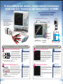
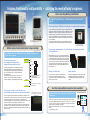
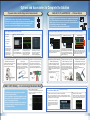
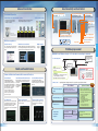
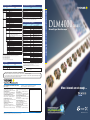
Standard Main Unit Accessories
Model and Suffix Codes
Model
Suffix code
Part Name
Description
Quantity
Mixed Signal Oscilloscope: 8ch, 350 MHz
Power cord
1
DLM4058*1
Mixed Signal Oscilloscope: 8ch, 500 MHz
Passive probe 701939 (500MHz, 1.3m)*1
4
-D
UL/CSA standard
Protective front cover
1
-F
VDE standard
Soft carrying case for probes
1
-Q
BS standard
Printer roll paper (for /B5 option)
1 roll
-R
AS standard
Rubber leg cap
1 set
-H
GB standard
User's manuals*
-N
NBR standard
-HE
English Message and Panel
-HC
Chinese Message and Panel
-HK
Korean Message and Panel
-HG
German Message and Panel
-HF
French Message and Panel
-HL
Italian Message and Panel
-HS
Spanish Message and Panel
Passive probe*1
701939
10MΩ(10:1)/500MHz/1.3m
/L16
Logic 16bit
Miniature passive probe
701946
10MΩ(10:1)/500MHz/1.2m
/B5
Built-in printer
Active probe(PBA1000)
701912
1 GHz bandwidth, 100 kΩ(10:1), 0.9 pF
Memory expansion
During continuous measurement: 6.25Mpoints;
Single mode: 25Mpoints (when interleave mode ON: 62.5Mpoints)
FET probe
700939
900 MHz bandwidth, 2.5 MΩ(10:1), 1.8 pF
/M1*2
100:1 high voltage probe
701944
400 MHz bandwidth, 1.2 m, 1000 Vrms
100:1 high voltage probe
701945
250 MHz bandwidth, 3 m, 1000 Vrms
Differential probe(PBDH1000)
701924
1 GHz bandwidth, 1 MΩ(50:1), max. ±25V
/M2*2
Memory expansion
During continuous measurement: 12.5Mpoints;
Single mode: 62.5Mpoints (when interleave mode ON: 125Mpoints)
Differential probe(PBDH0150)
701927
150 MHz bandwidth, max. ±1400 V,
1 m extension lead
/P8*3
Eight probe power connectors
500MHz differential probe
701920
500 MHz bandwidth, max. ±12 V
/C1
GP-IB Interface
200MHz differential probe
701922
200 MHz bandwidth, max. ±20 V
/C8
Internal storage (7.2 GB)
100MHz differential probe
700924
100 MHz bandwidth, max. ±1400 V
/G2*4
User defined math
100MHz differential probe
701921
100 MHz bandwidth, max. ±700 V
/G4*4
Power supply analysis function (includes /G2)
/F1*5
UART trigger and analysis
High voltage 50MHz
differential probe
701926
50 MHz bandwidth, max. 5000 Vrms
/F2*
I C+SPI trigger and analysis
15MHz differential probe
700925
15 MHz bandwidth, max. ±500 V
/F3*5
UART+I2C+SPI trigger and analysis
Current probe(PBC100)*2
701928
100 MHz bandwidth, max. 30 Arms
/F4*6
CAN+LIN trigger and analysis
Current probe(PBC050)*2
701929
50 MHz bandwidth, max. 30 Arms
/F5*6
FlexRay trigger and analysis
Current probe*2
701930
10 MHz bandwidth, max. 150 Arms
/F6*6
FlexRay+CAN+LIN trigger and analysis
Current probe*2
701931
2 MHz bandwidth, max. 500 Arms
/E1*7
Four additional 701939 probes (8 in total)
Deskew correction signal source
701936
For deskew between voltage and current
/E2*7
Attach four 701946 probes*8
Probe stand
701919
Round base, 1 arm
/E3*7
Attach eight 701946 probes*8
Printer roll paper
B9988AE
One lot: 10 rolls, 10 m each
MATLAB tool kit
701991
MATLAB plug-in software
701992-SP01
Viewer software (standard edition)
701992-GP01
Viewer software (MATH edition)
GO/NO-GO cable
366973
GO/NO-GO signal output
Soft carrying case
701968
For DLM4000
701969-E
EIA standard-compliant
701969-J
JIS standard-compliant
Power cord
Language
Option
5
1 set
2
*1: When /E1 option is selected, eight 701939 probes are included. When either /E2 or /E3 option is selected, no 701939 probe
is included.
*2: Start guide as the printerd material, and User's manuals as CD-ROM are included.
Accessories (sold separately)
Name
2
*1: Logic probes are not included. Please order the accessory logic probe 701988/701989 sold separately.
*2: Only one of these can be selected at a time.
*3: Specify this option when using current probes or differential probes that don't support probe interface.
*4: Only one of these can be selected at a time.
*5: Only one of these can be selected at a time.
*6: Only one of these can be selected at a time.
*7: Only one of these can be selected at a time.
*8: The 701939 probes are not included when this option is specified.
Xviewer
Rack mount kit for DLM4000
Logic probes
Model
Description
Mixed Signal Oscilloscope DLM4000
DLM4038*1
DLM4000 Series
Mixed Signal Oscilloscope
*1: As the accessories for 701939 probe, various adapters are available. Please refer to DL Series Accessories brochure.
*2: Current probes' maximum input current may be imited by the number of the probes used at a time.
Name
Model
Logic probe(PBL100)
701988
1MΩ input resistance, max. toggle frequency 100 MHz, 8 inputs
Description
Logic probe(PBL250)
701989
100kΩ input resistance, max. toggle frequency 250 MHz, 8 inputs
[ DLM is a registered trademark of Yokogawa Electric Corporation.]
Any company's names and product names appearing in this document are the registered trademarks or
trademarks of their respective companies.
NOTE
"Before operating the product, read the user’s manual thoroughly for
proper and safe operation."
Yokogawa's Approach to Preserving the Global Environment
• Yokogawa's electrical products are developed and produced in facilities that have received ISO14001 approval.
• In order to protect the global environment,Yokogawa's electrical products are designed in accordance with Yokogawa's Environmentally Friendly
Product Design Guidelines and Product Design Assessment Criteria.
YOKOGAWA METERS & INSTRUMENTS CORPORATION
Global Sales Dept.
YOKOGAWA CORPORATION OF AMERICA
2 Dart Road, Newnan, GA. 30265-1094 U.S.A.
Phone: +1-770-253-7000 Facsimile: +1-770-254-0928
YOKOGAWA EUROPE B. V.
Euroweg 2 3825 HD Amersfoort, THE NETHERLANDS
Phone: +31-88-4641000 Facsimile: +31-88-4641111
YOKOGAWA ENGINEERING ASIA PTE. LTD.
5 Bedok South Road, Singapore 469270 SINGAPORE
Phone: +65-6241-9933 Facsimile: +65-6241-2606
YOKOGAWA AMERICA DO SUL LTDA.
Praca Acapulco, 31-Santo Amaro, Sao Paulo/SP, BRAZIL CEP-04675-190
Phone: +55-11-5681-2400
Facsimile: +55-11-5681-4434
YOKOGAWA ELECTRIC KOREA CO., LTD.
C&M Sales Seoul Office
1301-1305, 13rd floor, Kolon digital tower, 106-1,
Yangpyongdong-5Ga, Yeongdeungpo-Gu, Seoul, 150-105,
Korea
Phone: +82-2-2628-3810 Facsimile: +82-2-2628-3899
Subject to change without notice.
Tachihi Bld. No.2, 6-1-3 Sakaecho, Tachikawa-shi, Tokyo, 190-8586 Japan
Phone: +81-42-534-1413 Facsimile: +81-42-534-1426
YOKOGAWA AUSTRALIA PTY. LTD.
Tower A/112-118 Talavera Road Macquarie Park, NSW 2113
Australia
Phone: +61-2-8870-1100 Facsimile: +61-2-8870-1111
Represented by:
When 4 channels are not enough …
YOKOGAWA INDIA LTD.
Plot No. 96. Electronic City Complex, Hosur Road, Bangalore 560100, INDIA
Phone: +91-80-4158-6000 Facsimile: +91-80-2852-1442
YOKOGAWA SHANGHAI TRADING CO., LTD.
4F Tower D, Cartelo Crocodile Building, No.568 West Tianshan
Road, Shanghai, CHINA
Phone: +86-21-6239-6363 Facsimile: +86-21-6880-4987
YOKOGAWA MIDDLE EAST B. S. C.(C)
P.O.BOX 10070, Manama, Building 577, Road 2516,
Busaiteen 225, Muharraq, BAHRAIN
Phone: +973-17-358100 Facsimile: +973-17-336100
YOKOGAWA ELECTRIC CIS LTD.
Grokholskiy per. 13, Build. 2, 4th Floor, 129090, Moscow
RUSSIAN FEDERATION
Phone: +7-495-737-7868 Facsimile: +7-495-737-7869
All Rights Reserved, Copyright© 2012, Yokogawa Meters & Instruments Corporation.
[Ed : 02/b]
Printed in Japan, 305(KP)
Bulletin DLM4000-00EN
12.1” LCD enables eight waveforms to be easily observed.
Portable
Options & Accessories
This combination with the optional
PBDH0150 High-Voltage Differential Probe,
creates a compact and
multi-channel floating voltage and
current measuring system.
Functions & Features
The portable eight-channel DLM4000 is
the daily instrument of choice.
four-direction
selection button
6.6
kg
Jog shuttle and
rotary knob
178mm
Operability & Software
.1
12
h
inc
355mm
Two USB Terminals on
Front Panel
Typical Demanding Applications for the Eight-Channel DLM4000
8ch
Motor Control & Inverter Circuit Development
Key to efficient and reliable high-performance
electric motors is the modern inverter design, or
‘Intelligent Power Module’. Multi-channel,
high-speed waveform measurement is an absolute
necessity. Four channels are simply not enough.
Boasting eight true analog inputs, the DLM4000
empowers today’s engineer with a convenient and
comprehensive measurement system.
Example: 3 voltage & 3 current measurements of a 3-phase motor
Measurement of the gate-drive signals of six IGBTs within the inverter
8ch
Electronic Control Unit & Mechatronic Test
CAN / LIN / FlexRay
UART / I2C /SPI
Numerous I/O analog, digital, and serial-bus waveforms
surrounding the Electronic Control Unit (ECU) must be
measured. The DLM4000 offers ample channel-count
and architecture to monitor eight analog channels and up
to 24-bits of logic input while simultaneously performing
protocol analysis such as UART, I2C, SPI, CAN, LIN and
FlexRay. The DLM4000 can speed up the the R&D
process. Four channels are not enough.
Example: Analog I/O and serial bus controller signals
Stringent realtime test of digital waveforms in the analog domain.
02
4ch Limitation of 4ch Scope
Whole-system measurement is impossible
with a four-channel scope; the real difficulty
is measuring the timing between IGBT gate
signals within the inverter. Voltage and
current measurements between 3 phases
and the IO of the motor driver IC is a very
challenging test with a four-channel scope.
The truly practical solution is an
eight-channel MSO.
4ch Limitation of 4ch MSO
The additional logic inputs of a four-channel
MSO mixed-signal oscilloscope provides
enough channels, but this method has a
blind-spot. Digital waveform analysis using
logic inputs alone cannot reveal anomalies
such as voltage drift, noise, distortion or
ringing, and measure rise-fall times. ECU
testing requires stringent examination of all
digital waveforms – and analog input
channels are the best tool for the job.
Channel 8 is Convertible to
8-Bit Logic Input
(Standard Feature)
former model
DL7480
Modest 178 mm Depth
Half of the former model DL7480
Specifications
Eight Analog Input Channels
(Yokogawa Probe Interface Compliant)
Additional 16-bits of
Input Logic,
for a total of 24-bits
(Optional)
Product Introduction
For today’s challenging power electronics, automotive electronics and mechatronics:
Only one scope will do – the world's only eight-channel oscilloscope - the DLM4000.
Typical General Applications for the Eight-Channel DLM4000
8ch
Power Supply & Power Converter Test
During the evaluation of a power supply design, it is
necessary to measure noise, ripple, voltage margin and
current , as well as timing margins and the jitter of the
startup-shutdown sequences. As the number of waveforms
in modern power supply designs is increasing, especially for
intelligent digitally-controlled power supplies, battery
management systems, and wireless power supply systems a four-channel oscilloscope is not enough.
Example: Start-up sequence test of multi-output power supply or Converter
Primary /secondary voltage/current and power supply control signal
8ch
Troubleshooting, total system test
For laboratory and field troubleshooting, the ability to
measureas many suspicious signals as possible enables
quick solutions to be found.
The measurement time for system testing is often very
limited.
The 8 channels of the DLM4000 provide the capability to
measure more signals at one time, both now and to meet
future needs.
Recorder
Limitation of Recorder
A modern multi-channel recorder provides
enough channels and long record times;
however, due to modest sample and update
rates, the recorder is unlikely to be
successful at measuring high-speed
waveforms in the vicinity of CPUs & FPGA
such as communication signals,
high-frequency noise, and fast waveform
anomalies.
of two
4ch Limitation
4 channel Scopes
When four channels are not enough, it is
common to connect two separate four
channel scopes. This approach is not only
cumbersome but inter-waveform timing can
lack credibility and post-processing of the
waveform data files is twice as much work.
The sensible approach is an eight-channel
MSO.
Example: Troubleshooting of infrequent problems
Comprehensive stability test of the whole system
03
Product Introduction
Features, Functionality, and Operability – satisfying the needs of today's engineers.
Best-in-class Deep Memory & Architecture
Extra Deep Memory (125 Mega-Points) Enables Long-Duration Measurement
For fast-short waveforms
the comprehensive trigger suite
captures the waveforms you need!
In addition to basic trigger functions such as Edge, State, and Pulse
Width – Advanced trigger types are provided, including Edge OR
between multiple channels, Serial Bus trigger in which A combination of two bus signals is possible, or an A and B combination of
different trigger types.
This comprehensive trigger suite means you capture the correct
waveforms - even for fast and complicated sets of waveforms
containing combinations of analog, digital, and serial bus signals.
Edge trigger
Enhanced triggers
Edge
Edge OR
Edge (qualified)
State
Pulse width
State width
Serial: (optional) FlexRay/CAN/LIN/UART/I2C/SPI
: (standard) user-defined
TV : NTSC/PAL/SDTV/ HDTV/user defined
B triggers
A Delay B
A to B(n)
You can replay waveforms later, so you'll never miss an abnormal waveform
- History Function –
With the DLM4000 series, up to 20,000 previously captured waveforms
can be saved in the automatically segmented acquisition memory without
sacrificing acquisition rate. This History function, enables you to display
just one or all of the previously captured waveforms (history waveforms)
on screen. You can also perform cursor measurement, computation, and
other operations on history waveforms. Using the History function, you
can find and analyze rarely-occurring abnormal signals which may not
cause a trigger to occur.
Specifications
Use the DLM4000 like an eight-channel memory recorder or select faster sampling rates up to
1.25 GS/s across all channels!
Dual-window zooming enables
two separate areas to be displayed.
(Center: ScopeCORE fast data processing IC)
Operability & Software
Reliable capture, from fast-short pulses to long recordings
Options & Accessories
Portrait, compact body
DLM2000 Mixed signal oscilloscope series
For-four channel measurements in Single shot mode, you can add the /M2 memory
expansion option which provides a large memory of up to 125 Mpoints. Even at a fast
sampling rate of 1.25 GS/s, records as long as 100 milli-seconds can be captured.
Yokogawa’s proprietary ScopeCORE IC assures responsiveness even for long record
lengths. ScopeCORE maintains a responsive waveform display even when parametric
measurements and waveform calculations are used and defines the architecture and
power of the DLM4000
In order to find and display the desired parts of the signal within the long memory,
powerful waveform search and a unique dual-window zoom function are provided.
Functions & Features
No-compromise ScopeCORE Architecture - the DLM4000 manages super-long record lengths
with ease
History search function
Replay function
You can search the 20,000 previously captured waveforms
for history waveforms that meet specified search criteria.
You can also perform cursor measurement and other types of
analysis on the search results.
Waveforms can be displayed one at a time, using the rotary
knob. With the Replay function, history waveforms can be
automatically played back, paused, fast-forwarded, and
rewound.
Dual bus (combination trigger of 2 serial busses)
Force Trigger
Force a trigger manually
For long term recording, 'roll mode' gives you
both realtime measurements and the waveform detail!
Selecting a long Time/Div setting automatically sets the DLM4000 into ‘Roll Mode’, which
performs just like a recorder. During roll mode, powerful real-time waveform processing such
as filtering, pulse counting and rotary counting can be executed simultaneously.
This means that the DLM4000 can observe a PWM and encoder waveform – analysis of these
waveforms in realtime is normally challenging – but the DLM4000 does it.
Furthermore, checking the waveform by using the powerful zoom feature and parametric
measurements is also possible during roll mode acquisition. This enables ongoing realtime
waveforms to be analysed without interrupting or pausing the acquisition. Many oscilloscopes
simply cannot do this.
04
Save time using unattended supervisory data acquisition
During Roll Mode, real-time waveform processing
such as PWM-filtering or pulse-counting means
un-interrupted recording
With built-in GO/NO-GO testing, unattended data acquisition becomes
a powerful tool.
A GO/NO-GO test result can be determined using customizable trigger conditions including
waveform zoning, parameter measurement, and other criteria. For either a GO or a NO-GO test
result, an action can be executed such as sounding a buzzer, saving the current waveform, or
sending a notification to a designated e-mail address.
Waveforms in which an abnormality occurred can be saved for confirmation and analysis at a
later time.
Let the DLM4000 save you time.
Abnormal waveform detected
Buzzer
Action specified
for NO-GO
Output to printer
Save waveform
E-mail
data file
transmission
05
Product Introduction
Options and Accessories to Complete the Solution
For power device circuit voltage/current measurement
CAN, LIN, I 2C, SPI, & UART(RS232) … Protocol Analysis
Eight analog input channels enables four pairs of voltage and current
measurements, thereby supporting today’s high-speed and sophisticated power
electronics circuit development. Optional analysis functions and accessories
support the comprehensive measurement of power electronic devices.
Node 1
Node n
CAN_H
CAN_L
SCL
SDA
SCL
SDA
Device #1
Power Analysis
Serial bus analysis function (/F1, /F2, /F3, /F4, /F5, /F6)
Example: Switching Loss Analysis
Serial-Bus Auto-Setup Saves Time
Device #2
Options & Accessories
Power supply analysis function (/G4)
Triggering and real-time Decoding
Hardware-based Decoding
Functions & Features
The DLM4000 offers advanced serial-bus analysis – saving precious development
time of ECUs and Embedded Systems. Eight analog input channels means that
multiple analog, serial-bus, and logic waveforms can be easily and simultaneously
observed whilst preserving their relative timing.
Up to four serial-buses can be analysed at the same time.
Dual Bus Analysis
-Switching Loss
-Safe Operating Area
I2C
Hex
-Joule Integral
Power Measurement
Auto Setup!
The built-in algorithm fine tunes
Power Loss calculations.
User-specified parameters include
device such as IGBTs and MOSFETs.
By dividing the long memory into segments,
the SOA (safe operating area) can be
analysed and, peak voltages between
switching cycles can be compared by
overlaying or one-by-one replay.
It is also possible to display a list of
the switching loss of each cycle and
save the results. By clicking a value
in the list, the corresponding
waveform will be directly displayed.
Intelligent serial-bus auto-setup feature enables
quick and easy setup. The bit-rate and voltage
thresholds are set automatically.
Symbol
Serial-bus waveforms are processed in realtime
by a dedicated processor. Decoded serial-bus
data is displayed alongside the bus waveform in
a user-selected format (Binary, HEX, or ASCII).
Symbol display based on a user-defined symbol
library is also easily setup.
Many systems contain multiple serial buses. The
DLM4000 analyzes four different serial-bus types
simultaneously. A combination trigger of two
different serial buses is also possible.
Easy Probing for Floating Signals
−High-Voltage Differential Probe−
Wide Range of Current Measurement
−Current probe−
Enables Precise Power Measurement
−Deskew correction signal source−
Analyzing High-speed Differential Signals
−PBDH1000 Differential Probe−
Probing Fast & Slow Logic Signals
−PBL100 & PBL250 Logic Probe−
High-density IC and PCB Probing
−701946 Miniature passive probe−
The High Voltage Differential Probe range includes
models such as the compact PBDH0150
(1400Vpeak) as well as the 701926 (7kVpeak).
The PBC100 and PBC050 high-bandwidth current
probes measure DC to 100MHz and 50MHz at up
to 30Arms. The 701931 is available for higher
currents up to 500Arms. The current probe range
covers a wide range of applications.
When measuring very fast switching devices,
probe delay time correction (de-skew) is crucial.
The 701936 signal source and auto de-skew
feature makes de-skewing quick and and simple.
The PBDH1000 differential probe features high
input-resistance, wide bandwidth, and a wide
input-voltage range. The PBDH1000 is perfect for
measuring the noise or surge voltage of in-vehicle
high-speed serial bus waveforms, including CAN
and FlexRay.
A generous assortment of probe tip accessories
assures flexible probing options.
Logic signals are not always fast. In some cases,
high input resistance is important. Yokogawa
offers two types of logic probes, PBL100 (100
MHz, 1 MΩ), which has mimimal loading, and
the PBL250 (250 MHz, 100 kΩ), ideal for probing
high-speed logic waveforms.
The 701946 is an ultra-compact passive probe for
measuring high-speed waveforms on ICs and in
high-density circuitry.
Various accessories maximise safety and
performance.
PBDH0150(701927)
150 MHz bandwidth
±1.4kV
PBC100(701928) / PBC050(701929)
DC to 100 MHz / DC to 50 MHz
30 Arms
701936
Deskew correction
signal source
Specifications
Automated measurement of
power parameters such as
active power, apparent
power, power factor etc.
(Calculation of three-phase
power is also possible)
SPI
Operability & Software
-Harmonic Analysis
PBDH1000(701924)
1.0GHz bandwidth
1 MΩ, approx 1.1pF
PWM, F-V, FFT, Diff/Integ … For an Increasingly Mechatronic World
Examples of Standard Computations:
The DLM4000 features advanced, powerful, and flexible
waveform computation abilities.
An increasing number of mechatronics applications require
measurements on the computational-result of a waveform,
and not on the input waveform itself.
Examples include PWM control signals, pulse-signals from
rotating-shaft applications, vibration-sensor data, and
accelerometer waveforms.
Real-time Low-Pass Filter, Add, Subtract, & Multiply Waveforms,
Integral, Pulse Count, Rotary-Count of Encoder A/B Signal,
XY Display, Power Spectrum
Input pulse
(Frequency)
User-Defined Math (/G2)
Customizable User-Defined Equations
Example of the functions in /G2 option, User Define Math:
Expansion of FFT Calculation
Duty cycle analysis for PWM waveform, F-V conversion, High-pass/Low-pass/Band-pass filtering,
moving average, differential-integral, trigonometric, exponential-logarithm, arithmetic calculation of
multiple channels, DA conversion of logic signals
In addition to power spectrum, advanced FFT functions
such as coherence and transfer function calculations
are available for detailed frequency-domain analysis.
User-defined math performs computation on
input-waveforms and math-channel results;
user-defined math can also use parametric
measurement results within a computation
expression.
Computed waveform
(F-V conversion)
F-V conversion of frequency pulse (/G2 option)
06
07
Comfortable Operation
The push function for each knob enables
fine adjustments to be made or puts the
setting back to the default.
Probe power terminal x8 (optional)
Ethernet (1000BASE-T)
Control from a PC
For current and differential probes that
don't support the Yokogawa probe interface.
Monitor & Control from a PC.
Network Data Transfer & Email.
Multi-color LED for clarity
Speed-sensitive knob behavior creates a natural response.
The scope intelligently responds to the operator.
USB-PC Connection
terminal
Control from a PC.
Mount to PC as External
storage.
GO/NO-GO Output terminal
USB 2.0 peripheral connection terminal x2
Supports USB storage, USB mouse and keyboards.
RGB video signal output terminal
Connection to an external monitor
Built-in user guidance
Thumbnail can be viewed full-size
Multiple Languages
The "?" button gets the operator fast and friendly
online help. No more need to consult the user's
manual.
Thumbnails of waveform data, waveform image data, and Wave-Zone
files can be displayed. The image and file names are shown so that you
can view screen image contents while copying or deleting files.
Select from
9 languages.
mouse
Trigger output
keyboads
External trigger input
PC efficiency improvement
DLM4000 is not Windows based, so it’s safer when connecting to networks.
Password protection and
selectable server function
assures security.
Ethernet
Thumbnail can be viewed full-size
Flexible and Powerful Features
Advanced Waveform Parameter Measurement Functions
Statistical Analysis
Trend and Histogram of Waveform Parameters
User-defined Waveform Parameters
Max/Mean/Freq/Rise/Fall/Delay.....,
29 different parameters are available.
Statistical processing of parameters, such
as Min, Max, Mean and Standard deviation
from multiple acquisitions, is also possible.
The Yokogawa original “cycle statistic”
and “history statistic” measurement
functions in combination with its long
memory and 8-channel inputs, helps the
analysis of e periodic mechatronics and
power electronics signals.
Waveform parameters can be displayed in list, trend and
histogram formats. It ispossible to find a characteristic
value in the list
display and jump to
the actual waveform
by clicking it.
Create customised waveform parameter
measurements using the freeform equation editor.
Calculation of three-phase power is also possible
(/G4 option)
Internal storage
Standard:1.8 GB
Optional: 7.2 GB
On PCs
USB
•Display can be monitored on
the browser.
On PCs
DLM4000’s internal storage
can be recognized by a PC
as an external USB storage
device. Transferring files is
easy even when a USB
thumb drive can’t be used.
On DLM4000
•A hard drive of the PC on the network can be selected
as the save destination (FTP connection)
•Mail sending in automatic GO/NO-GO judgment.
Software Control
http://tmi.yokogawa.com/ea/products/oscilloscopes/oscilloscopes-application-software/
Free Software
Off-line waveform display and
analysis
XviewerLITE –Basic check–
Zoom, V-cursor, conversion to CSV format
Variety of Display Formats
Automated GO/NO-GO Judgment
Parallel logic signals can be easily analysed using
the Bus display and bit assignment functions. A
State display is possible by using a clock edge to
normalise the input bits. The optional DA
calculation function is useful for evaluating AD/DA
converters.
Many types of display format are supported such
as XY, FFT, histogram.
GO/NO-GO judgment using polygon zoning or
waveform parameters is possible without
programming.
XWirepuller
Remote monitor and operation
Transferring image files
Data transfer to a PC
Control library “TMCTL”
Command control
Custom software
development
08
For Visual Studio
LabVIEW instrument driver
Optional Software
Trial version
available
available
Xviewer –Advanced Analysis–
Advanced and useful functions are supported.
Good for precise, off-line waveform analysis.
• Waveform observation and analysis
• Cursor, Parameteric Measure
• Statistical Analysis
• Multiple file display
• Advanced waveform operations
• Comment, marking, printing and making report
• Optional Math computation feature
• Remote monitor
• Instruments communication function
• Transferring waveform & image files
Waveform monitoring on a PC
Logic Measurement
Specifications
PC Connectivity Options
Operability & Software
Graphical online help
Options & Accessories
By pushing the knob,
trigger level is set to the center
of the waveform automatically.
Functions & Features
Dedicated knobs assure analog-like, intuitive operation
GP-IB connection terminal (optional)
Product Introduction
Broad Connectivity and Easier Control
Advanced User-Interface
DL-Term
Interactive tool
MATLAB Tool Kit
Remote control from MATLAB and data file
importing.
09
AB triggers
Frequency bandwidth
DLM4038
DLM4058
Input channels
350 MHz
(standard) 8 analog channels or 7 analog channels + 8bit logic
500 MHz
(/L16 option)
Input coupling setting
Input impedance
Max. DC offset
setting range
1 MΩ
50 Ω
1 MΩ
50 Ω
1 MΩ
50 Ω
DC accuracy*
Offset voltage accuracy*1 2 mV to 50mV/div
100 mV to 500 mV/div
1 V to 10 V/div
1
±(1.5% of 8 div + offset voltage accuracy)
±(1% of setting +0.2 mV)
±(1% of setting + 2 mV)
±(1% of setting + 20 mV)
Isolation between channels
Residual noise level*3
A/D resolution
Maximum sample rate
Real time sampling mode Interleave OFF
Interleave ON
Repetitive sampling mode
Maximum record length
Standard
/M1
/M2
Ch-to-Ch deskew
Time axis setting range
Time base accuracy*1
Logic Signal Input
Number of inputs
Standard
/L16
Maximum toggle frequency*1
Compatible probes
Min. input voltage
Input range
Max. nondestructive input voltage
Threshold level setting range
Input impedance
Maximum sampling rate
Maximum record length
Standard
/M1
/M2
Triggers
Trigger modes
Trigger type, trigger source A triggers
10
1.25 GS/s
2.5 GS/s
125 GS/s
Repeat / Single / Single Interleave
1.25 M / 6.25 M / 12.5 MPoints
6.25 M / 25 M / 62.5 MPoints
12.5 M / 62.5 M / 125 MPoints
±100 ns
1 ns/div to 500 s/div (steps of 1-2-5)
±0.002%
Functions
Waveform acquisition modes
High Resolution mode
Sampling modes
Accumulation
Accumulation time
Roll mode
Zoom function
Zoom factor
Scroll
Search functions
History memory
Max. data
History search
Replay function
Cursor
Snapshot
Display
Types
Computation & Analysis Functions
Parameter measurement
Statistical computation of parameters
Statistics modes
Trend/Histogram display of wave parameters
Computations (MATH)
8 bit (excl. 8 ch input and logic input)
24bit (16bit when 8 ch is used)
Model 701988: 100 MHz
Model 701989: 250 MHz
701988, 701989 (8 bit input)
(701980, 701981 are available)
701988: 500 mVp-p
701989: 300 mVp-p
Model 701988: ±40 V
Model 701989: threshold ±6V
±40 V (DC + ACpeak) or 28 Vrms (when using
701989)
Model 701988: ±40 V (setting resolution of 0.05 V)
Model 701989: ±6 V (setting resolution of 0.05 V)
701988: Approx. 1 MΩ/approx. 10 pF
701989: Approx. 100 kΩ/approx. 3 pF
1.25 GS/s
Repeat / Single
1.25 M / 6.25 MPoints
6.25 M / 25 MPoints
12.5 M / 62.5 MPoints
Computable no. of traces
Max. computable memory length
Auto, Auto Level, Normal, Single, N-Single
Edge
CH1 to CH8, Logic, EXT, LINE
Edge OR
CH1 to CH8
Edge Qualified CH1 to CH8, Logic, EXT
State
CH1 to CH8, Logic
Pulse width CH1 to CH8, Logic, EXT
State width CH1 to CH8, Logic
TV
CH1 to CH8
Serial Bus
2
I C (optional) CH1 to CH8, Logic
SPI (optional) CH1 to CH8, Logic
UART (optional)CH1 to CH8, Logic
FlexRay (optional)CH1 to CH8
CAN (optional) CH1 to CH8
LIN (optional) CH1 to CH8
User defined CH1 to CH8
Power supply analysis (/G4 option)
Power analysis
Reference function
Action ON trigger
Modes
Actions
XY
FFT
Histogram
User-defined math
(/G2 option)
Normal, Envelope, Average
Max. 12 bit (the resolution of the A/D converter
can be improved equivalently by placing a
bandwidth limit on the input signal.)
Real time, interpolation, repetitive sampling
Select OFF, Intensity (waveform frequency by
brightness), or Color (waveform frequency by
color)
100 ms to 100 s, Infinite
Enabled at 100 ms/div to 500 s/div (depending on
the record length setting)
Two zooming windows can be set independently
(Zoom1, Zoom2)
×2 to 2.5 points/10div (in zoom area)
Auto Scroll
Edge, Edge Qualified, State, Pulse Width, State
Width
I 2C (option), SPI (option), UART (option),
CAN (option), LIN (option), FlexRay (option)
2,500 (record length 1.25 kPoints, with standard)
10,000 (record length 1.25 kPoints, with /M1 option)
20,000 (record length 1.25 kPoints, with /M2 option)
Select Rect, WAVE, Polygon, or Parameter mode
Automatically displays the history waveforms
sequentially
Specified or average waveforms
∆T, ∆V, ∆T & ∆V, Marker, Degree
Currently displayed waveform can be retained on screen
Max, Min, P-P, High, Low, Amplitude, Rms, Mean,
Sdev, IntegTY+, IntegTY, +Over, -Over, Pulse
Count, Edge Count, V1, V2, ∆T, Freq, Period, Avg
Freq, Avg Period, Burst, Rise, Fall, +Width, -Width,
Duty, Delay
Min, Max, Ave, Cnt, Sdev
Continuous, Cycle, History
Up to 2 trend or histgram display of specied wave
parameters
+, -, ×, Filter (Delay, Moving Avg, IIR Lowpass, IIR
Highpass), Integ, Count / Rotaly count, user defined
math (optional)
4 (Math1, to Math4)
Standard model: 6.25 MPoints,
/M1 memory expansion option: 25 MPoints,
/M2 memory expansion option: 62.5 MPoints
Up to 4 traces (REF1/to REF4) of saved
waveform data can be displayed and analyzed
All Condition, Zone, Param, Rect, Polygon
Buzzer, Print, Save, Mail, Go/Nogo out
Displays XY1, to XY4 and T-Y simultaneously
Number of points: 1.25k, 12.5k, 125k, 250k
Window functions: Rectangular, Hanning, Flat-Top
FFT Types: PS (LS, RS, PSD, CS, TF, CH are
available with /G2 or /G4 option)
Displays a histogram of acquired waveforms
The following operators can be arbitrarily
combined in equations:
+, -, ×, /, SIN, COS, TAN, ASIN, ACOS, ATAN,
INTEG, DIFF, ABS, SQRT, LOG, EXP, LN, BIN,
DELAY, P2 (power of 2), PH, DA, MEAN, HLBT,
PWHH, PWLL, PWHL, PWLH, PWXX, FV,
DUTYH, DUTYL,
The maximum record length that can be
computed is as well as standard math functions
For Pwr1 and Pwr2, selectable from 4 analysis types
Deskweing between the voltage and current
waveforms can be executed automatically.
Switching loss
Total loss / switching loss, power waveform display,
Automatic measurement and statistical analysis of
power analysis items (Wp, Wp+, Wp-, Abs.Wp, P, P+,
P-, Abs.P, Z)
Safety operation area SOA analysis by X-Y display, using voltage as X axis,
and current as Y axis is possible
Harmonic analysis
Basic comparison is possible with following standard
Harmonic emission standard IEC61000-3-2 edition
2.2, EN61000-3-2(2000), IEC61000-4-7 edition 2
Joule integral
Joule integral (I2t) waveform display,
automatic measurement and statistical analysis is
possible
I2C Bus Signal Analysis Functions (/F2 & /F3 Options)
Bus transfer rate: 3.4 Mbit/s max.
Applicable bus
I2C bus
Address mode: 7 bit/10 bit
SM bus
Complies with System Management Bus
I2C Trigger modes
Every Start, Address & Data, Non-Ack, General
Call, Start Byte, HS Mode
Analyzable signals
All analog, logic and Math channels
Analysis results displays
Analysis no., time from trigger position (Time
(ms)),1st byte address, 2nd byte address, R/W,
Data, Presence/absence of ACK, information
Auto setup function
Auto setting of threshold value, time axis scale,
voltage axis scale, and display of analysis results
Analyzable no. of data
Search function
Analysis results save function
300,000 bytes max.
Searches data that matches specified address
pattern, data pattern, and acknowledge bit
condition
Analysis list data can be saved to CSV-format files
SPI Bus Signal Analysis Functions (/F2 & /F3 Options)
Trigger types
3 wire/4 wire
After assertion of CS, compares data after
arbitrary byte count and triggers.
Analyzable signals
All analog, logic and Math channels
Analysis results displays
Analysis no., time from trigger position (Time
(ms)),1st byte address, 2nd byte address, R/W,
Data, Presence/absence of ACK, information
Byte order
MSB/LSB
Auto setup function
Auto setting of threshold value, time axis scale,
voltage axis scale, and display of analysis results
Analyzable no. of data
300,000 bytes max.
Decode bit length
Specify data interval (1 to 32 bits), decode start
point, and data length
Analysis results displays
Analysis no., time from trigger position (Time
(ms)), Data 1, Data 2
Auxiliary analysis functions
Data search function
Analysis result save function
Analysis list data can be saved to CSV-format files
UART Bus Signal Analysis Functions (/F1 & /F3 Options)
Bit rate
1200 bps, 2400 bps, 4800 bps, 9600 bps,19200 bps,
user defined (an arbitrary bit rate from 1 k to 10 Mbps
with resolution of 100 bps)
Data format
Select a data format from the following 8 bit (Non
Parity) / 7 bit Data + Parity / 8 bit + Parity
UART Trigger modes
Every Data, Data, Error (Framing, Parity)
Analyzable signals
All analog, logic and Math channels
Auto setup function
Auto setting of bit rate, threshold value, time axis
scale, voltage axis scale, and display of analysis
results
Analyzable no. of frames
300,000 frames max.
Analysis results displays
Analysis no., time from trigger position (Time(ms)),
Data (Bin, Hex) display, ASCII display, and
Information.
Auxiliary analysis functions
Data search
Analysis result save function
Analysis list data can be saved to CSV-format files
CAN Bus Signal Analysis Functions (/F4 & /F6 Options)
Applicable bus
CAN version 2.0A/B, Hi-Speed CAN (ISO11898),
Low-Speed CAN (ISO11519-2)
Analyzable signals
All analog and Math channels
Bit rate
1 Mbps/500 kbps/250 kbps/125 kbps/83.3 kbps/
33.3 kbps
User defined ( an arbitrary bit rate from 10 kbps to
1 Mbps with resolution of 100 bps)
CAN bus Trigger modes
SOF, ID/DATA, ID OR, Error(enabled when loading
physical values/symbol definitions)
Auto setup function
Auto setting of bit rate, threshold value, time axis
scale, voltage axis scale, and display of analysis
results
Analyzable no. of frames
100,000 frames max.
Analysis results displays
Analysis no., time from trigger position (Time
(ms)), Frame type, ID, DLC, Data, CRC,
presence/absence of Ack, information
Auxiliary analysis functions
Data search and field jump functions
Analysis result save function
Analysis list data can be saved to CSV-format files
LIN Bus Signal Analysis Functions (/F4 & /F6 Options)
Applicable bus
LIN Rev. 1.3, 2.0, 2.1
Analyzable signals
All analog and Math channels
Bit rate
19.2 kbps, 9.6 kbps, 4.8 kbps, 2.4 kbps, 1.2 kbps
User defined (an arbitrary bit rate from 1 kbps to
20 kbps with resolution of 10 bps)
LIN bus Trigger modes
Break Synch, ID/DATA, ID OR, and ERROR
trigger
Auto setup function
Auto setting of bit rate, threshold value, time axis
scale, voltage axis scale, and display of analysis
results
Analyzable no. of frames
100, 000 frames max.
Analysis results displays
Analysis no., time from trigger position (Time (ms)),
ID, ID-Field, Data, CheckSum, information
Auxiliary analysis functions
Analysis result save function
Data search and field jump functions
Analysis list data can be saved to CSV-format files
FlexRay Bus Signal Analysis Functions (/F5 & /F6 Options)
Applicable bus
FlexRay Protocol Version2.1
Analyzable signals
All analog and Math channels
Bit rate
10Mbps, 5Mbps, 2.5Mbps
FlexRay bus Trigger modes
Frame Start, Error, ID/Data, ID OR
Auto setup function
Auto setting of bit rate, threshold value, time axis
scale,voltage axis scale, and display of analysis
results
Analyzable no. of frames
5,000
Analysis results displays
Analysis no., time from trigger position (Time(ms)),
Segment (Static or Dynamic),Indicator, FrameID,
PayLoad length, Cycle count, Data, Information
Auxiliary analysis function
Data search
Analysis result save function
Analysis list data can be saved to CSV-format files
GP-IB (/C1 Option)
Electromechanical specifications
Protocol
Auxiliary Input
Rear panel I/O signal
Probe interface terminal (front panel)
Probe power terminal (side panel)
Internal Storage
Capacity
Conforms to IEEE std. 488-1978 (JIS C 1901-1987)
Conforms to IEEE std. 488.2-1992
External trigger input, external trigger output,
GO-NOGO output, video output
8 terminals
8 terminals (/P8 option)
Standard model: Approx. 1.8 GB
/C8 option: Approx. 7.2 GB
Built-in Printer (/B5 Option)
Built-in printer
USB Peripheral Connection Terminal
Connector
Electromechanical specifications
Supported transfer standards
Supported devices
USB-PC Connection Terminal
Connector
Electromechanical specifications
Supported transfer standards
Supported class
Ethernet
Connector
Transmission methods
Supported services
112 mm wide, monochrome, thermal
USB type A connector × 2 (front panel)
USB 2.0 compliant
Low Speed, Full Speed, High Speed
USB Mass Storage Class Ver. 1.1 compliant mass
storage devices
USB HID Class Ver.1.1 compliant mouse,
keyboad
USB type B connector × 1
USB 2.0 compliant
High Speed, Full Speed
USBTMC-USB488 (USB Test and Measurement
Class Ver. 1.0)
Specifications
Bandwidth limit
-34 dB@ analog bandwidth (typical value)
The larger of 0.4 mV rms or 0.05 div rms
(typical value)
8bit (25LSB/div)
Max. 12 bit (in High Resolution mode)
FULL, 200 MHz, 100MHz, 20 MHz, 10 MHz,
5 MHz, 2 MHz, 1 MHz, 500 kHz, 250 kHz,
125 kHz, 62.5 kHz, 32 kHz, 16 kHz, 8 kHz
(can be set for each channel)
12.1-inch TFT color liquid crystal display
1024 × 768 (XGA)
Measurement
parameters
Automated measurement of power parameters for
up to four pairs of voltage and current waveforms
Values can be statistically processed and calculated
Urms, Unm, Udc, Urmn, Uac, U+pk, U-pk, Up-p
Irms, Imn, Idc, Irmn, Iac, I+pk, I-pk, Ip-p
P, S, Q, Z, λ, Wp, Wp+, Wp-, Abs.Wp, q, q+, q-,
Abs.q
Operability & Software
Frequency characteristics (-3 dB attenuation when inputting a sinewave of amplitude ±3div)*1*2
DLM4038
DLM4058
1 MΩ(when using passive probe)
100 mV to 100 V/div DC to 350 MHz DC to 500 MHz
20 mV to 50 mV/div DC to 300 MHz DC to 400 MHz
50 Ω
10 mV to 500 mV/div DC to 350 MHz DC to 500 MHz
2 mV to 5 mV/div
DC to 300 MHz DC to 400 MHz
Display
Display
Power Measurement
Options & Accessories
Voltage axis sensitivity
setting range
Max. input voltage
CH1 to CH8
(CH1 to CH7 when using logic input)
AC, DC, DC50 Ω, GND
1 MΩ ±1.0%, approximately 20 pF
50 Ω ±1.0% (VSWR 1.4 or less, DC to 500MHz)
2 mV/div to 10 V/div (steps of 1-2-5)
2 mV/div to 500 mV/div (steps of 1-2-5)
150 Vrms
Must not exceed 5 Vrms or 10 Vpeak
±1V (2 mV/div to 50 mV/div)
±10V (100 mV/div to 500 mV/div)
±100V (1 V/div to 10 V/div)
±1V (2 mV/div to 50 mV/div)
±5V (100 mV/div to 500 mV/div)
Force trigger
Trigger level setting range CH1 to CH8
Trigger level setting resolution CH1 to CH8
Trigger level accuracy*1 CH1 to CH8
Window Comparator
10 ns to 10 s (Edge, Edge
Qualified, State, Serial Bus)
A to B(N)
1 to 109 (Edge, Edge Qualified,
State, Serial Bus)
Dual Bus
Serial bus only
Force a trigger manually
±4 div from center of screen
0.01 div (TV trigger: 0.1 div)
±(0.2 div + 10% of trigger level)
Center/Width can be set on individual Channels
from CH1 to CH8
Functions & Features
Basic Specifications
Analog Signal input
Input channels
8 analog channels + 16bit logic or
7 analog channels + 24bit logic
A Delay B
RJ-45 connector × 1
Ethernet (1000BASE-T/100BASE-TX/10BASE-T)
Server: FTP, VXI-11, HTTP
Client: FTP, SMTP, SNTP, LPR, DHCP, DNS
General Specifications
Rated supply voltage
Rated supply frequency
Maximum power consumption
External dimensions
100 to 240 VAC
50 Hz/60 Hz
250 VA (when printer is used)
426 (W) × 266 (H) × 178 (D) mm (when printer
cover is closed, excluding protrusions)
Approx. 6.6kg
With no options
5 ˚C to 40 ˚C
Weight
Operating temperature range
*1 Measured under standard operating conditions after a 30-minute warm-up followed by calibration.
Standard operating conditions:
Ambient temperature: 23˚C ±5˚C
Ambient humidity: 55 ±10% RH
Error in supply voltage and frequency: Within 1% of rating
*2 Value in the case of repetitive phenomenon. The frequency bandwidth of a single-shot phenomenon is the smaller of the
two values, DC to sampling frequency/2.5 or the frequency bandwidth of the repetitive phenomenon.
*3. When the input section is shorted, the acquisition mode is set to Normal, accumulation is OFF, and the probe attenuation
is set to 1:1.
External Dimensions
Unit: mm
266
Model
426
9
Models
Product Introduction
DLM 4000 Series
Specification
13.4
178
23
11
Standard Main Unit Accessories
Model and Suffix Codes
Model
Suffix code
Part Name
Description
Quantity
Mixed Signal Oscilloscope: 8ch, 350 MHz
Power cord
1
DLM4058*1
Mixed Signal Oscilloscope: 8ch, 500 MHz
Passive probe 701939 (500MHz, 1.3m)*1
4
-D
UL/CSA standard
Protective front cover
1
-F
VDE standard
Soft carrying case for probes
1
-Q
BS standard
Printer roll paper (for /B5 option)
1 roll
-R
AS standard
Rubber leg cap
1 set
-H
GB standard
User's manuals*
-N
NBR standard
-HE
English Message and Panel
-HC
Chinese Message and Panel
-HK
Korean Message and Panel
-HG
German Message and Panel
-HF
French Message and Panel
-HL
Italian Message and Panel
-HS
Spanish Message and Panel
Passive probe*1
701939
10MΩ(10:1)/500MHz/1.3m
/L16
Logic 16bit
Miniature passive probe
701946
10MΩ(10:1)/500MHz/1.2m
/B5
Built-in printer
Active probe(PBA1000)
701912
1 GHz bandwidth, 100 kΩ(10:1), 0.9 pF
Memory expansion
During continuous measurement: 6.25Mpoints;
Single mode: 25Mpoints (when interleave mode ON: 62.5Mpoints)
FET probe
700939
900 MHz bandwidth, 2.5 MΩ(10:1), 1.8 pF
/M1*2
100:1 high voltage probe
701944
400 MHz bandwidth, 1.2 m, 1000 Vrms
100:1 high voltage probe
701945
250 MHz bandwidth, 3 m, 1000 Vrms
Differential probe(PBDH1000)
701924
1 GHz bandwidth, 1 MΩ(50:1), max. ±25V
/M2*2
Memory expansion
During continuous measurement: 12.5Mpoints;
Single mode: 62.5Mpoints (when interleave mode ON: 125Mpoints)
Differential probe(PBDH0150)
701927
150 MHz bandwidth, max. ±1400 V,
1 m extension lead
/P8*3
Eight probe power connectors
500MHz differential probe
701920
500 MHz bandwidth, max. ±12 V
/C1
GP-IB Interface
200MHz differential probe
701922
200 MHz bandwidth, max. ±20 V
/C8
Internal storage (7.2 GB)
100MHz differential probe
700924
100 MHz bandwidth, max. ±1400 V
/G2*4
User defined math
100MHz differential probe
701921
100 MHz bandwidth, max. ±700 V
/G4*4
Power supply analysis function (includes /G2)
/F1*5
UART trigger and analysis
High voltage 50MHz
differential probe
701926
50 MHz bandwidth, max. 5000 Vrms
/F2*
I C+SPI trigger and analysis
15MHz differential probe
700925
15 MHz bandwidth, max. ±500 V
/F3*5
UART+I2C+SPI trigger and analysis
Current probe(PBC100)*2
701928
100 MHz bandwidth, max. 30 Arms
/F4*6
CAN+LIN trigger and analysis
Current probe(PBC050)*2
701929
50 MHz bandwidth, max. 30 Arms
/F5*6
FlexRay trigger and analysis
Current probe*2
701930
10 MHz bandwidth, max. 150 Arms
/F6*6
FlexRay+CAN+LIN trigger and analysis
Current probe*2
701931
2 MHz bandwidth, max. 500 Arms
/E1*7
Four additional 701939 probes (8 in total)
Deskew correction signal source
701936
For deskew between voltage and current
/E2*7
Attach four 701946 probes*8
Probe stand
701919
Round base, 1 arm
/E3*7
Attach eight 701946 probes*8
Printer roll paper
B9988AE
One lot: 10 rolls, 10 m each
MATLAB tool kit
701991
MATLAB plug-in software
701992-SP01
Viewer software (standard edition)
701992-GP01
Viewer software (MATH edition)
GO/NO-GO cable
366973
GO/NO-GO signal output
Soft carrying case
701968
For DLM4000
701969-E
EIA standard-compliant
701969-J
JIS standard-compliant
Power cord
Language
Option
5
1 set
2
*1: When /E1 option is selected, eight 701939 probes are included. When either /E2 or /E3 option is selected, no 701939 probe
is included.
*2: Start guide as the printerd material, and User's manuals as CD-ROM are included.
Accessories (sold separately)
Name
2
*1: Logic probes are not included. Please order the accessory logic probe 701988/701989 sold separately.
*2: Only one of these can be selected at a time.
*3: Specify this option when using current probes or differential probes that don't support probe interface.
*4: Only one of these can be selected at a time.
*5: Only one of these can be selected at a time.
*6: Only one of these can be selected at a time.
*7: Only one of these can be selected at a time.
*8: The 701939 probes are not included when this option is specified.
Xviewer
Rack mount kit for DLM4000
Logic probes
Model
Description
Mixed Signal Oscilloscope DLM4000
DLM4038*1
DLM4000 Series
Mixed Signal Oscilloscope
*1: As the accessories for 701939 probe, various adapters are available. Please refer to DL Series Accessories brochure.
*2: Current probes' maximum input current may be imited by the number of the probes used at a time.
Name
Model
Logic probe(PBL100)
701988
1MΩ input resistance, max. toggle frequency 100 MHz, 8 inputs
Description
Logic probe(PBL250)
701989
100kΩ input resistance, max. toggle frequency 250 MHz, 8 inputs
[ DLM is a registered trademark of Yokogawa Electric Corporation.]
Any company's names and product names appearing in this document are the registered trademarks or
trademarks of their respective companies.
NOTE
"Before operating the product, read the user’s manual thoroughly for
proper and safe operation."
Yokogawa's Approach to Preserving the Global Environment
• Yokogawa's electrical products are developed and produced in facilities that have received ISO14001 approval.
• In order to protect the global environment,Yokogawa's electrical products are designed in accordance with Yokogawa's Environmentally Friendly
Product Design Guidelines and Product Design Assessment Criteria.
YOKOGAWA METERS & INSTRUMENTS CORPORATION
Global Sales Dept.
YOKOGAWA CORPORATION OF AMERICA
2 Dart Road, Newnan, GA. 30265-1094 U.S.A.
Phone: +1-770-253-7000 Facsimile: +1-770-254-0928
YOKOGAWA EUROPE B. V.
Euroweg 2 3825 HD Amersfoort, THE NETHERLANDS
Phone: +31-88-4641000 Facsimile: +31-88-4641111
YOKOGAWA ENGINEERING ASIA PTE. LTD.
5 Bedok South Road, Singapore 469270 SINGAPORE
Phone: +65-6241-9933 Facsimile: +65-6241-2606
YOKOGAWA AMERICA DO SUL LTDA.
Praca Acapulco, 31-Santo Amaro, Sao Paulo/SP, BRAZIL CEP-04675-190
Phone: +55-11-5681-2400
Facsimile: +55-11-5681-4434
YOKOGAWA ELECTRIC KOREA CO., LTD.
C&M Sales Seoul Office
1301-1305, 13rd floor, Kolon digital tower, 106-1,
Yangpyongdong-5Ga, Yeongdeungpo-Gu, Seoul, 150-105,
Korea
Phone: +82-2-2628-3810 Facsimile: +82-2-2628-3899
Subject to change without notice.
Tachihi Bld. No.2, 6-1-3 Sakaecho, Tachikawa-shi, Tokyo, 190-8586 Japan
Phone: +81-42-534-1413 Facsimile: +81-42-534-1426
YOKOGAWA AUSTRALIA PTY. LTD.
Tower A/112-118 Talavera Road Macquarie Park, NSW 2113
Australia
Phone: +61-2-8870-1100 Facsimile: +61-2-8870-1111
Represented by:
When 4 channels are not enough …
YOKOGAWA INDIA LTD.
Plot No. 96. Electronic City Complex, Hosur Road, Bangalore 560100, INDIA
Phone: +91-80-4158-6000 Facsimile: +91-80-2852-1442
YOKOGAWA SHANGHAI TRADING CO., LTD.
4F Tower D, Cartelo Crocodile Building, No.568 West Tianshan
Road, Shanghai, CHINA
Phone: +86-21-6239-6363 Facsimile: +86-21-6880-4987
YOKOGAWA MIDDLE EAST B. S. C.(C)
P.O.BOX 10070, Manama, Building 577, Road 2516,
Busaiteen 225, Muharraq, BAHRAIN
Phone: +973-17-358100 Facsimile: +973-17-336100
YOKOGAWA ELECTRIC CIS LTD.
Grokholskiy per. 13, Build. 2, 4th Floor, 129090, Moscow
RUSSIAN FEDERATION
Phone: +7-495-737-7868 Facsimile: +7-495-737-7869
All Rights Reserved, Copyright© 2012, Yokogawa Meters & Instruments Corporation.
[Ed : 02/b]
Printed in Japan, 305(KP)
Bulletin DLM4000-00EN