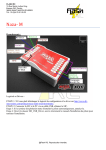
1
DJI Flame Wheel F450/F550 DJI Flame Wheel F450/F550 Congratulations on your purchase of a DJI Flame Wheel, prepared by I-Drone. Below you will find steps on how to get started with your multi rotor. Your bird has already been test flown, configured & firmware upgrades installed so that you can begin flying with ease and confidence. At the end of this document you will find links to the DJI website, these links include Video Tutorials, PDF manuals and the NAZA-M Assistant Software. The assistant software is a windows application and can only be run using a PC, a Mac OS platform is under development and hopes to be released in the coming months. Becoming familiar with the Assistant software is recommended, as you will tend to use the software to upgrade firmware updates when released by DJI, knowing how to adjust flight parameters and most importantly calibrating the flight controller from time to time will improve flight performance. List of parts shipped: • 1 x Fully assembled F450 or F550 Flamewheel + Naza-M Flight Controller + GPS upgrade module. • 3 x 4S 4000mAh LiPo battery (Plug type - 4.5mm bullet connectors) • 1 iMAX Battery Charger/Balancer + Australia power adaptor (2~6 Cell compatible) Manual attached seperately • 1 x 4.5mm Bullet Connector to Deans plug. Used to connect LiPo battery to iMAX charger when charging batteries. • 6 x 8” DJI Props (Recommended to be used with 4S LiPo batteries) • 6 x 10” DJI Props (Recommended to be used with 3S LiPo batteries) • 1 x Futaba T8FG or Devo 8s Transmitter & Receiver. • 1 x Landing Skid (Requires minimal assembly) • 4 x Zip ties (Used to fix legs to base plate of FlameWheel) Quick Start Guide: 1. Charge LiPo batteries & RC batteries. 2. Download product manuals and assistant software (Can be downloaded and read on both Mac or PC) 3. Familiarize yourself with product functions and capabilities. 4. Install Propellers in accordance with Flame Wheel manual. 5. Assemble and attach landing skid. 6. Connect batteries for both RC and multi rotor. Remember to follow correct procedure. 7. Calibrate the GPS/Compass for first flight. 8. Initiate motors using the correct method, sticks to bottom left or right. 9. Take throttle stick position to 50% and wait for motors to increase speed, then take up to 70% when ready to take off. 10. Practice basic moves, forward, backwards, left and right. Pay attention to the LED light indicator whilst flying. 11. Once ready to land take throttle position below 50% and ease the bird towards the ground. I-DRONE – WWW-I-DRONE.COM.AU 1 12. Once on the ground ensure motors are off, place the Radio Control on the ground and then disconnect the battery on the multi rotor. Lastly switch off the Radio Controller. *It is extremely important that you read and understand the DJI product user manuals prior to your first flight. Understanding the multi rotors capabilities and safety procedures is a must when RC flying. Step 1. Charging We have Included 1 x fully charged LiPo battery, begin charging your two other batteries. The Charger has been setup specifically for the LiPo battery supplied, however if the settings are no longer in the Charger please use these settings. Battery Type is LiPo & is to be charged at 4.0 Amps + 4S (14.8V). The Charger will alarm when complete & display the msg “FULL”. *Ensure you connect the balancer lead before starting charge. (refer to battery images for more information. Fully charge the Transmitter (Radio Controller) before flight. Use charger supplied or if using the Futaba controller you will need to charge the unit using the iMAX B6 charger & the Deans to Servo plug connector. You will also need to change the charger settings from LiPo battery to a Life battery. It is recommended to charge at 0.7Amps for the Futaba battery. Remove the battery from the futaba controller as per the owners manual and connect to the iMAX charger. Step 2. Familiarize yourself with the Transmitter and NAZA flight controller functions prior to flight. Familiarize NAZA-M FLIGHT CONTROL Please download and study the NAZA-M user manual from link provided. http://www.djiinnovations.com/download/naza-m-downloads/ It is recommended to print out the “LED Description” Chart, from the NAZA-M manual, and take with you when flying. This chart explains what each blinking light means and what to do when your multi rotor is powered up. Your multi rotor has a blinking LED light installed facing downwards so that in flight the pilot can visually see the light sequence and determine the flying mode and/or warnings. Knowing these light descriptions is critical to ensuring an enjoyable and safe flight, or more importantly reducing the chances of crashing your multi rotor. A few Key functions of the NAZA-M user manual to give close attention to are; Flight modes (GPS/ATT/Manual), what they are & how to switch between modes. Fail Safe function, how to use, when to use and how to recover from Fail safe. Low Voltage alarms, how to setup and what to do when flying. RADIO CONTROL – Devo8s/Futaba Both controllers are shipped with the owners manual. If you are new to the RC world then these manuals can seem a little confusing, It is recommended that you become familiar with at least the basic functions and adjustments initially. Once you clock up the hours flying, the manual will start to make more sense. Stick with it because it makes flying more challenging and exciting knowing the potential of the controller. We have labeled your controller so that you can clearly identify assigned sticks, switches, flight modes, fail safes and trims. These are guides to help you learn how your controller is configured, it is up to the pilot to be familiar with what each switch/function does and how to return to default setup. It is important that you learn the functions of each assigned switch as it is very likely that during transit that switches are bumped We have also setup the switches so that all are facing forwards, with the exception of the Flight Mode. The GPS mode switch is setup so that it is the only switch positioned facing the pilot. We have set it up this way so that the pilot is aware of the mode they are about to fly in, taking off in the wrong mode can lead to a crash. All other switches should be set forwards or away from the pilot. I-DRONE – WWW-I-DRONE.COM.AU 2 User Manuals can be located on the DJI website, link here. Step 3. Propeller Installation: REFER TO FLAME WHEEL USER MANUAL FOR CORRECT INSTALLATION Install Propellers, Landing skids, Batteries & Connect Once you have read the Flame wheel user manual you should have a basic understanding of the NAZA-M functions and the parts associated with the multi rotor. To protect your propellers during transit we have removed them prior to shipping and will require you to re install. Referring to the Flame Wheel PDF manual for your chosen model you will note that there will be two red frame arms on the bird. These arms identify the front of the multi rotor when built by I-Drone, meaning forwards is the direction in which these red arms are facing. The motors are identified 1, 2, 3, 4…. Position the multi rotor on a clear bench and that the red arms are pointing away, or are facing the direction you wish to fly. Basically you are standing behind the multi rotor. The number 1 motor will be the red arm on the right. Move counter clockwise to the second red arm, this is motor two. Continue moving counter clockwise identifying motor 3, motor 4 and so on… Each motor needs to spin a certain direction to create a balanced lift and this has been setup prior to shipping from I-Drone. Motor 1 turns counter clockwise (Left), motor 2 turns clockwise (Right), motor 3 turns counter clockwise, motor 4 turns clockwise. Basically all odd number motors turn CCW, and even numbered motors turn CW. Since the motors turn a certain direction so do the propellers. When installing the propellers to the motors ensure the right props are on the correct motors. Located near the centre of the props is an identification marking ie 8045 or 8045R. As per the FlameWheel manual all props with the marking “R” (8045R) MUST BE installed on all even numbered motors (2,4, & 6). Propellers with NO “R”, ie 8045, MUST BE installed on all odd numbered motors (1, 3, & 5). Propellers installed incorrectly we cause the multi rotor to crash upon take off. Once you have installed the propellers correctly use the supplied prop spanner to tighten the props, excessive force is not required, firm pressure is fine. Landing Skids: To Install the Landing skids supplied takes a few simple steps. Firstly pull all parts out of its packaging and lay on a flat surface. There will be 2 x Arched frames (in a U shape), 2 x 7mm tubing & 2 x 12mm tubing. Grab 1 x arch frames and 1 x 12mm tubing. Place the 12mm tube into the allocated slot at the top of the arch. It will require a little pressure to insert and will snap into place. Insert the other 12mm tube in the opposite side of the arch frame. Repeat this step with the other Arch frame piece. With the landing skid partly assembled grab the 7mm tubes and position them into place at the base of the arch legs. Again, this will require a little pressure and will snap into place. We have supplied you with 4 zip ties, use these to attach the multi rotor to the landing skids. To do so, place your multi rotor on top of the landing skid so that the base plate of the multi rotor sits flat on the 12mm tubes running between both arches. Depending on the model purchased there will be slots in the base plate of the FlameWheel. Use these slots to loop the zip ties through and secure tightly. Place two at the front and two at the rear of the base plate. Lock into place and check that the landing skids are firmly secured. I-DRONE – WWW-I-DRONE.COM.AU 3 Battery Connection: Install fully charged AA batteries to Devo8s, for Futaba install the liFe battery to base of the transmitter. Place fully charged LiPo battery onto Velcro strip on top plate of multi rotor, ensure that you centre the battery as much as possible to keep CG (Centre of Gravity) neutral. Lock in the battery using the adjustable Velcro strap. It makes for good practice to carry a multi meter with you when flying, checking the voltage of the battery prior to flying saves the risk of installing a dead battery from a earlier fight. It can happen and having your bird fall out of the sky because of a simple mistake is frustrating to say the least. Steps to powering up Multi rotor Ensure that all switches on the Radio Controller are in the correct positions and that GPS mode is selected. Turn on transmitter (Devo8s/Futaba), ensure throttle stick is at the bottom of its travel, Tx will alarm otherwise and will not bind to receiver. Plug LiPo battery into the power terminal on your multi rotor, ensuring that the power cable is attached below the arm so as to avoid the cord interfering with the propellers. Step 4. Binding & Identify Flight Mode. Ensure that the transmitter has “bound” with the RC receiver, there should be a solid light on the RC Receiver (Red light for Devo8S & Green light for Futaba). If the light is blinking, repeat step 3 by turning the power on & off. Ensure that the Transmitter is in GPS/Attitude mode, never use Manual mode. Refer to LED description chart. Check that all connections are correct and that the LED for the Flight Controller is blinking Green (GPS/ATT) or Yellow (Attitude) mode. If blinking only RED this means you are in Manual mode or Low Voltage warning. Once the multi rotor has warmed up (LED blinks 2 yellows for several minutes) it will then record its home position and activate the flight mode. It is recommended to calibrate the GPS on a regular basis, To calibrate the GPS you have to flick the flight mode switch on your Radio controller between GPS & Attitude mode quickly for 10 times. If done correctly the LED light on multi rotor will be a solid yellow light. Now hold the bird out in front of you keeping it horizontal to the ground, spin around 360 until the light turns green. Then turn the bird on its side and again spin around 360. The LED light should now blink Green. Calibrating the GPS/Compass helps ensure a smooth flight. *Refer to the NAZA-M user manual for exact method. Step 5. Start up & take off. Now that the multi rotor has been calibrated and is in the right flight mode, place in an open area and at least 5 meters away from people and/or objects. We strongly suggest flying in a wide open park whenever possible. Initiate motors start by placing both control sticks on the transmitter, to the bottom right hand or left hand corners. Motors will start. Take the throttle above 10% so as to keep motors running, if below 10% for longer than 2sec the motors will shut off and you will need to initiate them again. Check that it is clear to take off and that no persons are in harms way, including the pilot. Best to place I-DRONE – WWW-I-DRONE.COM.AU 4 the multi rotor 10 meters away from people. NOW, ready for take off. Take the throttle up to 50% using the left stick on RC, you will notice that the motors are not increasing. The latest firmware allows beginners to get a helping hand when taking off. Once the throttle stick is taken up to 60-70% the motors give an instant burst of power, which in turn gives your multi rotor lift off without crashing. Once off of the ground you can bring the throttle down to 50% when you are at the desire height/altitude , 50% throttle = Hover. When first learning to fly we suggest keeping the bird around 10-15 meters away from your self, and practicing simple maneuvers like forwards, backwards, left and right. Gradually combine the two stick movements and see the potential of these products. Step 6. Landing Step 7. Shut down When landing lower the throttle power slowly, anything below 50% will lower the birds altitude. Once close to the ground manage the power slowly until you have contact with the ground. Shut off the motors once you are happy with the landing. Again, if throttle power is below10% for longer than 3 secs the motors will automatically shut off. Now that you have landed and are either changing batteries for another flight or packing up for the day, you will need to power down your multi rotor. To do so we power down in the reverse order to that of powering up. 1. Disconnect the power terminals to the LiPo batteries on your multi rotor. 2. Turn the power switch off on the transmitter. Happy days, you’ve now experienced the flying craze and we are certain you will be back for more. Keep track of your charged and discharged batteries whilst out flying as it is easy to get them mixed up and reload a empty battery. It pays to carry rubber bands with you and can place one around a discharged battery to identify the difference, this is a cheap and effective method. Always fly responsibly and always fly away from areas where people are present. Fly to your abilities and it is always a good idea to fly in open spaces, practicing turns and the capabilities of the equipment. I-DRONE – WWW-I-DRONE.COM.AU 5 Contact Information If you have any further queries regarding your purchase please feel free to contact our Technical department. Technical Information Email: [email protected] Mobile: 0413167678 Helpful Links: DJI Product Manuals: http://www.dji-innovatsons.com/download/naza-m-downloads/ http://www.dji-innovations.com/download/flame-wheel-arf-downloads/ DJI Tutorials: http://www.dji-innovations.com/tutorial/naza-m-tutorials/ http://www.dji-innovations.com/tutorial/flame-wheel-tutorials/ I-DRONE – WWW-I-DRONE.COM.AU 6