1
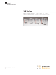
user manual
Hoefer SG500
Gradient maker
um SG500-IM/Rev.E0/08-12
Page finder
SG500 instructions................................................1
1. Generating linear gradients..................................2
Pouring gradients from the top ...........................4
Pouring gradients from the bottom.......................5
2. G
enerating convex and concave exponential
gradients...........................................................6
To generate an exponential gradient.....................7
3. Care and maintenance........................................9
4. Ordering information...........................................9
• pi
SG500 instructions
The Hoefer® SG500 gradient maker is designed
for producing linear gradients of aqueous
solutions ranging in volume from 100–500 ml.
The SG500 can be used to create convex and
concave exponential gradients with the addition
of a one-holed rubber stopper, a piece of rigid
tubing and a piece of flexible tubing. The unit
is fabricated from cast acrylic plastic sheet and
tubing. It is suitable for casting acrylamide pore
gradient gels and delivering salt gradients for
low pressure chromatography systems.
reservoir (back) chamber
mixing (front) chamber
Fig 1. Hoefer SG500
gradient maker.
Included but not shown:
Hose clamps (4)
outlet connector
(4 mm ID tubing)
slide stop
push-pull valve
connector channel
• p1
1. Generating linear gradients
To generate a linear gradient between two
concentrations, equal volumes of solutions of the
two concentrations are measured into the two
chambers of the gradient maker. As solution is
delivered out of the mixing chamber, an equal
volume flows in from the reservoir chamber
where it is rapidly diluted and mixed to uniformity by a magnetic stir bar. The initial concentration delivered will be that of the solution in
the mixing chamber, the final concentration will
be that of the reservoir chamber. For the most
consistent delivery of gradients, a peristaltic
pump is recommended.
1
ake sure all parts are clean and liquid flows freely
M
through all the connecting channel of the slide valve
and pump and delivery tubing.
2
open
closed
Fig 2. Open and closed positions
of slide valve.
• p2
Add a magnetic stir bar of the appropriate dimensions
(20–30 mm long) to the mixing chamber and place
the unit on a magnetic stirrer. If volumes will be less
than half the capacity of the unit, an identical stir bar
should be placed in the reservoir chamber as well to
balance the displacement and prevent backflow into
the reservoir when the chambers are first connected.
Connect tubing to the outlet connector and pump,
and adjust pump speed, if used. Position or connect
the tubing to the receiving vessel (gel casting unit,
column, etc.).
3
lose the slide valve (out on side of white slide stop
C
button, Fig 2). If the outlet tubing is not controlled
by a pump, clamp it off near the gradient former.
Add the required volume of the final solution to the
reservoir (back) chamber.
4
Note: If there is a substantial difference in densities
between the two solutions,
there will be a sudden flow
from the denser chamber
to the lighter chamber to
bring the two into hydrostatic
balance. This will result in
the gradient not being fully
linear. To avoid this, add
equal weights, rather than
volumes, of the solutions to
the appropriate chambers.
Carefully open the slide valve and allow just enough
solution to flow through the connector channel to fill
it to the edge of the mixing chamber, then close the
valve. Be sure no large bubbles remain to obstruct
flow through the channel.
5
dd the required volume of the starting solution to
A
the mixing chamber and start the magnetic stirrer.
6
Open the outlet tubing if clamped off.
7
Simultaneously start the pump.
8
If it is important that no bubbles disturb the
gradient, watch the delivery carefully and as soon
as the last of the solution has entered the pump
head, stop the pump and clamp off the tubing to
the receiving container.
9
Flush and rinse all parts thoroughly with distilled
water after use.
• p3
Pouring gradients from the top
Filling a container with a gradient (e.g. casting
acrylamide pore gradient gels) can be done either
dense solution first (“from the top”), or light
solution first (“from the bottom”).
To fill from the top:
1
Proceed as described in Section 1, putting light (final
or top) solution in the reservoir chamber (step 3) and
dense solution in the mixing chamber (step 5).
2
lace the delivery outlet against the upper edge of
P
the receiving container. Adjust the pump rate so that
the solution flows evenly down the side in a smooth,
continuous stream. The delivery speed should be slow
enough that the newly arriving solution does not mix
with the underlying solution.
Alternatively, using a rigid cannula at the end of the
delivery tubing, hold the tip of the cannula just above
the surface of the solution, raising it smoothly as the
container fills.
• p4
Pouring gradients from the bottom
This technique is commonly used in filling
multiple gel casting chambers.
1
Proceed as described in Section 1, putting dense
(final or bottom) solution in the reservoir chamber
(step 3) and light solution in the mixing chamber
(step 5).
2
In step 2, connect the outlet tubing to the bottom
inlet of a gel casting unit or to a cannula long enough
to reach the bottom of the receiving container. Adjust
the pump rate so that the solution is not forced up in
a “fountain” that mixes with the overlying solution.
3
If all of the gradient solution must be delivered to the
container, a displacement solution may be used. Just
as the last of the gradient mix is pumped out of the
mixing chamber, and before any air enters the tubing,
add an appropriate volume of a denser displacement
solution to the mixing chamber and pump it through
until all of the gradient mix has been delivered. It
is convenient to include a dye in the displacement
solution to visually track the boundary between the
gradient mix and the displacement solution.
• p5
2. Generating convex and
concave exponential gradients
Eq 1.
By holding the volume in the mixing chamber
constant (as opposed to declining for linear
gradients), the gradient generated will have an
exponential concentration curve. The mixing
volume in the SG500 unit can be held constant
by sealing the top of the mixing chamber with a
rubber stopper and tubing assembly (Fig 4). The
total volume of the gradient can be greater than
the maximum volume of the gradient former
because additional solution can be repeatedly
added to the reservoir chamber. Using Eq 1,
examples of the gradients generated by various
combinations of volumes and concentrations
listed in Table 1 are plotted in Fig 3. Concave
gradients are generated high concentration first,
and thus containers such as gel cassettes must
be filled from the top. Convex gradients must
be filled from the bottom. Most frequently used
is the concave pore gradient for increased resolution in the high molecular weight region of
acrylamide gels.
Table 1. Examples of concave and convex
exponential gradients
A
B
C
D
E
Cres*
0
1
1
1
0.5
Vres
500
500
100
500
500
Cmix
1
0
0
0.5
1
Vmix
100
100
500
100
100
*Volumes are relative.
C: concentration, V: volume, res: reservoir chamber,
mix: mixing chamber
• p6
1.0
0.9
relative concentration
Fig 3. Examples of
exponential gradients.
D
0.8
B
0.7
0.6
E
0.5
0.4
0.3
A
0.2
C
0.1
0.0
0%
20%
40%
60%
80%
100%
% of gradient delivered
To generate an exponential gradient:
1
ake sure all parts are clean and liquid flows freely
M
through all channels, stopcocks and tubing.
2
Assemble the stopper. Select a one-hole rubber stopper that fits securely in the top of the mixing chamber. Attach a short piece of flexible vinyl tubing that
can be clamped off to make an airtight seal to a rigid
piece of glass or plastic tubing that fits tightly in the
hole of the stopper. The stopper assembly should seal
the mixing chamber airtight when the slide valve is
closed and the outlet tubing is clamped off.
3
Add a magnetic stir bar of the appropriate dimensions (20–30 mm long) to the mixing chamber and
place the unit on a magnetic stirrer. Connect tubing
to the outlet connector and pump, then adjust pump
speed, if needed. Position or connect the tubing to
the receiving vessel (gel casting unit, centrifuge tube,
etc.) at top or bottom, as appropriate.
• p7
4
Close the slide valve and add a portion of the final
solution to the reservoir (back) chamber.
5
Carefully open the slide valve and allow just enough
solution to flow through the connector channel to fill
it to the edge of the mixing chamber, then close the
valve. Be sure no large bubbles remain to obstruct
flow through the channel.
6
Fig 4. Gradient maker with
plunger in place.
Add the required volume of the starting solution to the
mixing chamber. With the stopper tubing open, insert
the stopper assembly securely into the mixing chamber (Fig 4). Clamp off the tubing on the vent airtight.
7
Note: If the gradient volume
is larger than the reservoir will
hold, the additional volume
can be added during the gradient delivery. Do not allow the
reservoir chamber to go dry
as bubbles will be pulled into
the mixing chamber, changing
the dilution volume and
gradient shape.
Note: The entire solution
remaining in the mixing chamber is at the final concentration
and does not contribute further
to the gradient. If desired, it
can be used as a displacement
solution for convex gradients
unless it contains acrylamide.
• p8
tart the magnetic stirrer and unclamp the outlet
S
tubing if needed.
8
Simultaneously open the slide valve and start
the pump.
9
Stop the pump and remove the tubing from the
receiving container as soon as the last of the solution
has left the reservoir chamber.
Disconnect tubing. Flush and rinse all parts
thoroughly with distilled water after use.
3. Care and maintenance
The gradient maker should be cleaned
thoroughly with distilled water after use to
prevent polymerization or crystallization of
solutions in the chambers and stopcocks.
Do not use abrasives, acetone, pure alcohols
or organic solvents to clean this unit.
4. Ordering information
product
qty.
code no.
SG500 Gradient Maker, 500 ml total volume
1
SG500
Push-pull valve for salt gradient
1
SG500-10
Red outlet fitting, 4 mm
4
XPO10
Push-pull valve replacement
1
SG500-1
• p9
Hoefer, Inc.
84 October Hill Road
Holliston, MA 01746
Toll Free: 1-800-227-4750
Phone: 1-508-893-8999
Fax: 1-508-893-0176
E-mail: [email protected]
Web: www.hoeferinc.com
Hoefer is a registered trademark
of Hoefer, Inc.
© 2012 Hoefer, Inc. —
All rights reserved.
Printed in the USA.