1
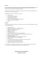
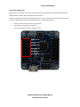
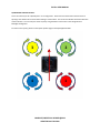
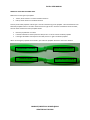
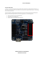
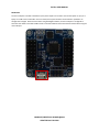
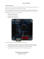
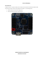
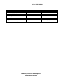
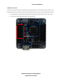
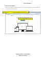
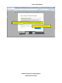
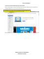
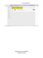
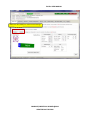
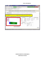
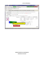
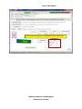
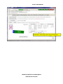
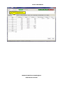
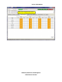
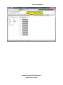
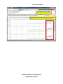
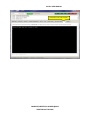
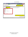
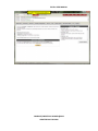
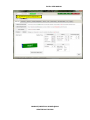
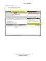
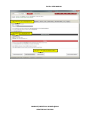
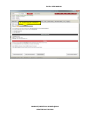
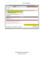
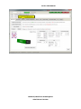
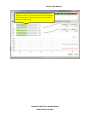
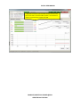
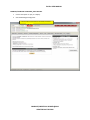
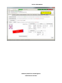
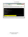
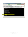
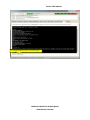
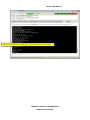
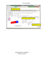
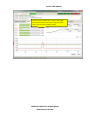
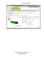
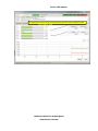
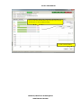
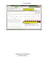
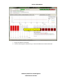
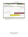
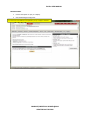
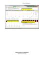
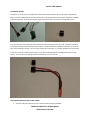
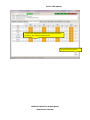
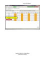
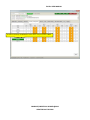
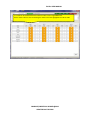
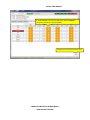
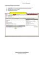
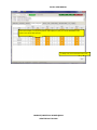
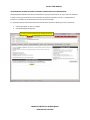
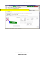
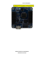
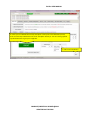
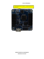
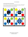
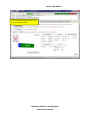
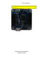
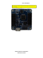
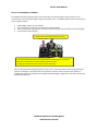
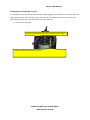
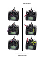
QUEEN HOBBY FLIP32+ MANUAL COMPILED/CREATED BY RCJOSEB @2014 UPDATED ON 07-30-2014 PURPOSE: This user manual covers topics needed to setup your Flip 32+ flight controller from ReadyToFlyQuads.com. All the pictures contained in this user manual, except for company logos or trademarks, were created by me and therefore may not be used elsewhere without prior permission. This manual may not be posted on any other website, blog or forum, etc. except for ReadyToFlyQuads.COM and the thread I created for it on RCGroups.COM. The following topics will not be covered in this user manual: Connecting a GPS Connecting a Mavlink enabled OSD Using a CPPM enabled receiver Firmware(s) other than BaseFlight GUIs other than Google Chrome BaseFlight Configurator Motor layouts other than Quadcopter X Tuning FEATURES: As of this writing the version of the Flip32+ is V2.3 Revision 6 and the firmware loaded is BaseFlight V2.3. The Flip 32+ features the following: Version 2.3 hardware STM32F103CB 32-bit processor running at 3.3V/72MHz MPU6050 3-axis MEMS gyro + accelerometer HMC5883L 3-axis magnetometer MS5611 Pressure sensor 16Mbit onboard SPI flash Six motor headers with support for various multirotor types ** Eight receiver headers with support for PWM, PPM and Spektrum satellite receivers. ** One battery voltage monitor header ** One Piezo buzzer header ** Pin headers mounting holes for telemetry, GPS and I2C support *** Onboard micro USB port for setup and configuration Three status LEDs 36mm (1.41732”) x 36mm (1.41732”) in size with 3.175 (0.125”) mounting holes 7.3 grams (0.2575 ounces) with headers soldered on Can be used as a stand-alone camera gimbal controller MultiWii-based configuration software for easy setup ** Pin headers can be either straight or right angled and can be soldered on for you by RTFQ for a small fee. *** Pin headers are not supplied by RTFQ and will need to be purchased separately. COMPILED/CREATED BY RCJOSEB @2014 UPDATED ON 07-30-2014 MY OPINION ON ESC/RECEIVER WIRES: When connecting ESC and receiver wires to the Flip32+, you will either use all three (ground, voltage, signal) wires or just one (signal) wire. ESC and receiver cables use servo type connectors with removable pins. It is best practice to remove the pin that will not be utilized from the connector, instead of cutting its wire. If you ever want to use that ESC or receiver cable again and the wire has been cut, you will have to re-solder it. The resulting connection may not be as reliable as it was before when it was intact. The pins with the wire intact can be removed by: Using a small flat blade screwdriver or knife to gently pry up the tab that holds the pin in place Sliding out the pin from the servo connector Wrap the pulled pin(s) using electric tape or shrink tubing so that there is no chance of a shortage Attach the pins to the existing wire with electric tape or shrink tubing COMPILED/CREATED BY RCJOSEB @2014 UPDATED ON 07-30-2014 FLIP32+ USER MANUAL MOTOR/ESC CONNECTIONS: Motors/ESCs are connected to the six sets of 3 pin headers that are located on the left hand side of the board. Motor/ESC #6 is at the top while motor/ESC #1 is at the bottom. Connect the ground (G), voltage (V) and signal (S) wires from only one of the ESCs (usually ESC #1) to the Flip32+ and for the remaining ESCs only connect the signal (S) wire. In the following picture: The outer most pin on the left is the ground pin (G) The middle pin is the power/voltage pin (V) The inner most pin on the right is the signal pin (S) G V S Motor/ESC #6 Motor/ESC #5 Motor/ESC #4 Motor/ESC #3 Motor/ESC #2 Motor/ESC #1 COMPILED/CREATED BY RCJOSEB @2014 UPDATED ON 07-30-2014 FLIP32+ USER MANUAL QUADCOPTER X MOTOR LAYOUT: This is the motor layout for a Quadcopter in an X configuration. Please note that the direction that the motor is spinning is the direction of the motor when looking at it from above. The red arrow indicates the forward direction of the multirotor. You can verify the motor layout by using the Motor Test function in the Google Chrome BaseFlight Configurator. For other motor layouts, please see the Flip32+ product page on ReadyToFlyQuads.COM. 3 2 4 1 COMPILED/CREATED BY RCJOSEB @2014 UPDATED ON 07-30-2014 FLIP32+ USER MANUAL PROPELLER TYPES AND SPIN DIRECTION: Multirotors use two types of propellers: Tractor, which rotates in a counter clockwise direction Pusher, which rotates in a clockwise direction One way to tell which propeller is which type is to look at the lettering on the propeller. Some manufacturers will label their propellers with an L for left or CCW and an R for right or CW. But if the manufacturer omits the letter, then the other method is to look at propeller blades: Place the propeller flat on a table If the left side blade is raised up from the table, then it’s a left or counter clockwise propeller If the right side blade is raised up from the table, then it’s a right or clockwise propeller When connecting the propellers to the motors, just match the propeller direction to the motor direction. Left side blade is raised up Clockwise Propeller Counter Clockwise Propeller Right side blade is raised up COMPILED/CREATED BY RCJOSEB @2014 UPDATED ON 07-30-2014 FLIP32+ USER MANUAL RECEIVER CONNECTIONS: A receiver is connected to the eight sets of 3 pin headers that are located on the right hand side of the board. In a basic setup, only the first four sets of 3 pin headers are used, which are roll, pitch, throttle and yaw. The remaining four are auxiliary connections. Connect the signal (S), voltage (V) and ground (G) wires from only one receiver channel (usually Throttle) to the Flip32+ and for the remaining channels only connect the signal (S) wire. In the following picture: The inner most pin on the left is the signal pin (S) The middle pin is the voltage pin (V) The outer most pin on the right is the ground pin (G) S Aileron (Roll) Elevator (Pitch) Throttle Rudder (Yaw) Aux #1 Aux #2 Aux #3 Aux #4 COMPILED/CREATED BY RCJOSEB @2014 UPDATED ON 07-30-2014 V G FLIP32+ USER MANUAL MICRO USB: The micro USB port is located at the bottom (rear) of the Flip32+ and is used to connect the Flip32+ to your pc or laptop via a USB to micro USB cable. Once connected, the Flip 32+ firmware can be flashed or updated or its configuration changed. Please note that when using BaseFlight firmware, the micro USB port is configured to share the same UART as the OSD and Blue Tooth so the OSD and Blue Tooth must be disconnected when using the micro USB port. Micro USB COMPILED/CREATED BY RCJOSEB @2014 UPDATED ON 07-30-2014 FLIP32+ USER MANUAL BLUE TOOTH CONNECTION: A Blue Tooth module is connected to the single 4 pin header that is located to the right of the micro USB port. You will need to solder the header pins on yourself as they are not included. Once connected, the Blue Tooth module lets you connect to your Flip32+ via a wireless connection from your pc, laptop or Android device. Please note that you cannot have a USB cable plugged into the micro USB port when utilizing the Blue Tooth connection. In the following picture: The first pin is the ground pin (G) The second pin is the voltage pin (V) The third pin is the receive pin (RX) The fourth pin is the transmit pin (TX) G V RX TX The Blue Tooth module is connected to the Flip32+ in the following manner: The receive pin (RX) on the Flip 32+is connected to the transmit (TX) pin on the Blue Tooth module The transmit pin (TX) on the Flip 32+ is connected to the receive (RX) pin on the Blue Tooth module The voltage (V) pin is connected to the voltage (VCC) pin on the Blue Tooth module The ground (G) pin is connected to the ground (G) pin on the Blue Tooth module COMPILED/CREATED BY RCJOSEB @2014 UPDATED ON 07-30-2014 FLIP32+ USER MANUAL VOLTAGE BATTERY (VBAT) CONNECTION: The VBAT connector is a single 2 pin header that is located on the left hand side of the board just below the motor/ESC pin headers. This connector lets the Flip32+ monitor the multirotor main battery voltage and works in conjunction with the BEEP connector in order to produce a beeping sound when the battery voltage is too low. Connect a two wire cable between your power distribution board and the VBAT or your multirotor main battery balance lead and the VBAT. In the following picture: The outer most pin on the left is the voltage (+) pin The inner most pin on the right is the ground (-) pin + - COMPILED/CREATED BY RCJOSEB @2014 UPDATED ON 07-30-2014 FLIP32+ USER MANUAL BEEP CONNECTION: The BEEP connector is a single 2 pin header that is located on the left hand side of the board just below the VBAT connector and is used to connect a Piezo style buzzer to the Flip32+. In the following picture: The outer most pin on the left is the voltage (+) pin The inner most pin on the right is the ground (-) pin + - COMPILED/CREATED BY RCJOSEB @2014 UPDATED ON 07-30-2014 FLIP32+ USER MANUAL STATUS LEDs: The three status LEDs are located at the top (front) of the Flip32+. In the following picture: The outer most led on the left is the power led and is Blue in color The middle led is a status led and is Red in color The inner most led on the right is a status led and is Green in color COMPILED/CREATED BY RCJOSEB @2014 UPDATED ON 07-30-2014 FLIP32+ USER MANUAL LED STATES: EVENT LEFT BLUE LED MIDDLE RED LED RIGHT GREEN LED Connect to pc/laptop Powered on Flashing Firmware Armed Accelerometer Calibration Magnetometer Calibration Accelerometer Trimming Solid Solid Solid Solid Solid Solid Solid Blinks then turns off Blinks then turns off Solid then blinks then turns off Off Off Off Off Blinks then turns off Blinks then turns off Solid then blinks then turns off Solid Solid then turns off Blinks rapidly then turns off Blinks with each stick movement COMPILED/CREATED BY RCJOSEB @2014 UPDATED ON 07-30-2014 FLIP32+ USER MANUAL POWERING THE FLIP32+ There are several ways to power the Flip32+ but the easiest method is to use the 5V BEC wire from ESC #1. Once powered, the Flip32+ can then be used to power additional devices, such as the receiver and Blue Tooth module. Connect ESC #1 to the motor/ESC connection #1 on the Flip32+ with all three wires (G, V and S) intact Connect the remaining ESCs utilizing only the signal (S) wire G V S Motor/ESC #1 COMPILED/CREATED BY RCJOSEB @2014 UPDATED ON 07-30-2014 FLIP32+ USER MANUAL THE FLIP32+ DRIVER: In order to be able to communicate to the Flip 32+, your pc/laptop requires a CP210x USB to UART Bridge VCP driver. Depending on your operating system and hardware, your pc or laptop may recognize the UART Bridge once it is plugged in. If not, you can download the driver from: http://www.silabs.com/products/mcu/pages/usbtouartbridgevcpdrivers.aspx The Google Chrome BaseFlight Configurator also contains a link to the latest driver. COMPILED/CREATED BY RCJOSEB @2014 UPDATED ON 07-30-2014 FLIP32+ USER MANUAL BASEFLIGHT FIRMWARE: The best and easiest way to obtain the latest BaseFlight firmware is to use the Google Chrome BaseFlight Configurator. However, this requires an internet connection which may not always be available. For those moments, you can download the firmware to your pc or laptop and then access it from the Google Chrome BaseFlight Configurator. Latest production release of BaseFlight Firmware: https://code.google.com/p/afrodevices/downloads/list Latest development release of BaseFlight Firmware: https://github.com/multiwii/BaseFlight/blob/master/obj/BaseFlight.hex GOOGLE CHROME BASEFLIGHT CONFIGURATOR: The Google Chrome BaseFlight Configurator is available from the Google Chrome store for free but requires a Google account and the Google Chrome web browser to access, download and use. Download and install the Google Chrome web browser from: https://www.google.com/chrome/browser/ Download and install the Google Chrome BaseFlight Configurator from the Google Chrome store: https://chrome.google.com/webstore/category/apps COMPILED/CREATED BY RCJOSEB @2014 UPDATED ON 07-30-2014 FLIP32+ USER MANUAL INSTALLING GOOGLE CHROME: Please note that Google may change the installation screens and/or the installation process for Google Chrome at any time so let the installer beware. 1. Start your favorite browser and go to https://www.google.com/chrome/browser/ 2. Click on the Download Chrome button. COMPILED/CREATED BY RCJOSEB @2014 UPDATED ON 07-30-2014 FLIP32+ USER MANUAL 3. Uncheck Set Google Chrome as my default browser unless desired. 4. Click on the Accept and Install button. COMPILED/CREATED BY RCJOSEB @2014 UPDATED ON 07-30-2014 FLIP32+ USER MANUAL 5. Click on the Save File button. 6. Locate the executable file and run it. 7. The install will place the Google Chrome icon on your desktop. COMPILED/CREATED BY RCJOSEB @2014 UPDATED ON 07-30-2014 FLIP32+ USER MANUAL INSTALLING THE GOOGLE CHROME BASEFLIGHT CONFIGURATOR: Please note that Google may change the installation screens and/or the installation process for Google Chrome BaseFlight Configurator at any time so let the installer beware. 1. Start Google Chrome and go to https://chrome.google.com/webstore/category/apps 7. The install will place the Google Chrome icon on your desktop. COMPILED/CREATED BY RCJOSEB @2014 UPDATED ON 07-30-2014 FLIP32+ USER MANUAL 2. Type BaseFlight Configurator in the search box and press the Enter key. EnterEy.me.google.com/webstore/category/apps 7. The install will place the Google Chrome icon on your desktop. COMPILED/CREATED BY RCJOSEB @2014 UPDATED ON 07-30-2014 FLIP32+ USER MANUAL 3. Click on the application icon. COMPILED/CREATED BY RCJOSEB @2014 UPDATED ON 07-30-2014 FLIP32+ USER MANUAL 4. Click on Launch App button. COMPILED/CREATED BY RCJOSEB @2014 UPDATED ON 07-30-2014 FLIP32+ USER MANUAL 5. Sign onto Google or create an account. COMPILED/CREATED BY RCJOSEB @2014 UPDATED ON 07-30-2014 FLIP32+ USER MANUAL 6. Click on Launch App button. COMPILED/CREATED BY RCJOSEB @2014 UPDATED ON 07-30-2014 7. The BaseFlight Configurator appears. COMPILED/CREATED BY RCJOSEB @2014 UPDATED ON 07-30-2014 FLIP32+ USER MANUAL The BaseFlight Configurator is enabled to run on your pc/laptop without the need for an internet connection. I was able to set this up my pc at home but the same process failed on two separate laptops running the same version of Windows. In addition, Google installed a Quick Launch Application icon on my taskbar so that I could launch the Google Chrome applications easily but that also failed on the laptops. Without having to go through that process, I figured out another way. 1. With the BaseFlight Configurator running, locate the application icon on your taskbar and right click on it. 2. Click on Pin this program to taskbar. 3. You can now run the configurator just by clicking twice on the icon. COMPILED/CREATED BY RCJOSEB @2014 UPDATED ON 07-30-2014 FLIP32+ USER MANUAL BASEFLIGHT CONFIGURATOR FEATURES AND BUTTONS: Dropdown boxes to select COM port and speed Connect/Disconnect button COMPILED/CREATED BY RCJOSEB @2014 UPDATED ON 07-30-2014 FLIP32+ USER MANUAL Checkbox allows auto-connection when Flip32+ is connected. COMPILED/CREATED BY RCJOSEB @2014 UPDATED ON 07-30-2014 FLIP32+ USER MANUAL Indicates hardware features available. Green for available. Red for not available. COMPILED/CREATED BY RCJOSEB @2014 UPDATED ON 07-30-2014 FLIP32+ USER MANUAL Options for receiving updates and sending usage data. This area displays status messages. COMPILED/CREATED BY RCJOSEB @2014 UPDATED ON 07-30-2014 FLIP32+ USER MANUAL Tabs to access features and functions. COMPILED/CREATED BY RCJOSEB @2014 UPDATED ON 07-30-2014 FLIP32+ USER MANUAL Accelerometer and Magnetometer (Compass) calibration buttons. COMPILED/CREATED BY RCJOSEB @2014 UPDATED ON 07-30-2014 FLIP32+ USER MANUAL Buttons to reset, backup or restore current settings. COMPILED/CREATED BY RCJOSEB @2014 UPDATED ON 07-30-2014 FLIP32+ USER MANUAL Area displays the multirotor type, magnetometer heading and orientation of Flip32+ COMPILED/CREATED BY RCJOSEB @2014 UPDATED ON 07-30-2014 FLIP32+ USER MANUAL Button to reset the Z axis and offset. COMPILED/CREATED BY RCJOSEB @2014 UPDATED ON 07-30-2014 FLIP32+ USER MANUAL Dropdown boxes to change various values. COMPILED/CREATED BY RCJOSEB @2014 UPDATED ON 07-30-2014 FLIP32+ USER MANUAL Displays battery voltage/current and RSSI data if sensors are installed. COMPILED/CREATED BY RCJOSEB @2014 UPDATED ON 07-30-2014 FLIP32+ USER MANUAL Save button. If you change a value, click the Save button! COMPILED/CREATED BY RCJOSEB @2014 UPDATED ON 07-30-2014 FLIP32+ USER MANUAL Tab used to change PID values COMPILED/CREATED BY RCJOSEB @2014 UPDATED ON 07-30-2014 FLIP32+ USER MANUAL Tab used to configure receiver channels. Dropdown boxes to change throttle points, rates and expo. Best to change these on the transmitter or leave as is. COMPILED/CREATED BY RCJOSEB @2014 UPDATED ON 07-30-2014 FLIP32+ USER MANUAL Tab used to configure AUX channels. COMPILED/CREATED BY RCJOSEB @2014 UPDATED ON 07-30-2014 FLIP32+ USER MANUAL Tab used to configure servos. COMPILED/CREATED BY RCJOSEB @2014 UPDATED ON 07-30-2014 FLIP32+ USER MANUAL Tab used to monitor GPS activity. COMPILED/CREATED BY RCJOSEB @2014 UPDATED ON 07-30-2014 FLIP32+ USER MANUAL Tab used to test motors and calibrate ESCs. Dropdown boxes to change refresh rates and scale size. Must be checked to enable motor test. COMPILED/CREATED BY RCJOSEB @2014 UPDATED ON 07-30-2014 FLIP32+ USER MANUAL Tab to display raw sensor data. Dropdown boxes to change refresh rates and scale size. COMPILED/CREATED BY RCJOSEB @2014 UPDATED ON 07-30-2014 FLIP32+ USER MANUAL Tab used to start a CLI session. COMPILED/CREATED BY RCJOSEB @2014 UPDATED ON 07-30-2014 FLIP32+ USER MANUAL Tab used to enable logging. Logging options. Buttons to select log file and start logging. COMPILED/CREATED BY RCJOSEB @2014 UPDATED ON 07-30-2014 FLIP32+ USER MANUAL CONNECTING THE FLIP32+ TO YOUR PC OR LAPTOP VIA A USB TO MICRO USB CABLE: This is the method I prefer so that I do not short out the USB connector on the Flip32+: 1. 2. Connect the USB to micro USB cable to the Flip32+ Connect the USB to micro USB cable to the pc or laptop DISCONNECTING THE FLIP32+ FROM YOUR PC OR LAPTOP: This is the method I prefer so that I do not short out the USB connector on the Flip32+: 1. 2. Disconnect the USB to micro USB cable from the pc or laptop Disconnect the USB to micro USB cable from the Flip32+ COMPILED/CREATED BY RCJOSEB @2014 UPDATED ON 07-30-2014 FLIP32+ USER MANUAL CHECKING THE FIRMWARE VERSION: 1. 2. Connect the Flip32+ to your pc or laptop. Start the BaseFlight Configurator. 3. Ensure the correct COM port and speed for your pc or laptop is selected. COMPILED/CREATED BY RCJOSEB @2014 UPDATED ON 07-30-2014 FLIP32+ USER MANUAL 4. Click on the red Connect button. COMPILED/CREATED BY RCJOSEB @2014 UPDATED ON 07-30-2014 FLIP32+ USER MANUAL 5. The firmware version is displayed here. COMPILED/CREATED BY RCJOSEB @2014 UPDATED ON 07-30-2014 FLIP32+ USER MANUAL UPDATING THE FIRMWARE: 1. 2. Connect the Flip32+ to your pc or laptop. Start the BaseFlight Configurator. 3. Ensure the Connect button indicates Connect. 4. Click on the Firmware Flasher button. COMPILED/CREATED BY RCJOSEB @2014 UPDATED ON 07-30-2014 FLIP32+ USER MANUAL 5. Read the boot loader warning. 6. Read the firmware warning. 7. Clock on the Load Firmware (Online) button. COMPILED/CREATED BY RCJOSEB @2014 UPDATED ON 07-30-2014 FLIP32+ USER MANUAL 8. Firmware file size is displayed here. 9. Firmware info is displayed here. 10. Click on the Flash Firmware button. COMPILED/CREATED BY RCJOSEB @2014 UPDATED ON 07-30-2014 FLIP32+ USER MANUAL 11. The flash progress is displayed. COMPILED/CREATED BY RCJOSEB @2014 UPDATED ON 07-30-2014 FLIP32+ USER MANUAL 12. The process is done when the bar is all Green. 13. Click on the Leave Firmware Flasher button. COMPILED/CREATED BY RCJOSEB @2014 UPDATED ON 07-30-2014 FLIP32+ USER MANUAL TRANSMITTER STICK CALIBRATION: This calibration process performs two very important tasks: Provides the Flip32+ the PWM pulse ranges generated by each channel and stick on your transmitter. Provides a means to verify the movement of your channels, in case one of them needs to be reversed. 1. 2. Connect the Flip32+ to your pc or laptop. Start the BaseFlight Configurator. 3. Click on the Connect button if not already connected. COMPILED/CREATED BY RCJOSEB @2014 UPDATED ON 07-30-2014 FLIP32+ USER MANUAL 4. Click on the Receiver tab. COMPILED/CREATED BY RCJOSEB @2014 UPDATED ON 07-30-2014 FLIP32+ USER MANUAL 5. Move the roll and yaw sticks on your transmitter left/right and observe the status bars. Each bar should move in the same direction as the stick controlling it. Reverse any channel on your transmitter that does not move correctly. COMPILED/CREATED BY RCJOSEB @2014 UPDATED ON 07-30-2014 FLIP32+ USER MANUAL 6. Move the pitch and throttle sticks on your transmitter up/down. Each bar should move to the left as the stick moves down and to the right as the stick moves up. Reverse any channel on your transmitter that does not move correctly. COMPILED/CREATED BY RCJOSEB @2014 UPDATED ON 07-30-2014 FLIP32+ USER MANUAL 7. Adjust the sub trims on your transmitter for each channel so that their center value is as close to 1500 as possible. I do not believe it will be an issue if the value is slightly over 1500. COMPILED/CREATED BY RCJOSEB @2014 UPDATED ON 07-30-2014 FLIP32+ USER MANUAL FAILSAFE CONSIDERATIONS: The failsafe feature is a function of the receiver and not the Flip32+ so a failsafe enabled receiver is required. When a failsafe is initiated, the Flip32+ receives a PWM throttle value that is lower than the current PWM throttle value and then those values or signals are sent to the ESCs to spin down or stop the motors. BaseFlight has a motor feature called MOTOR_STOP which is either enabled or disabled. By default, this value is disabled so that the motors idle up when the Flip32+ is armed. Ask yourself this: Do I want to use the motors idling up as an indicator to let me know the Flip32+ is armed? Do I think that I or someone can get hurt by the motors idling up if I accidentally arm the Flip32+? Do I think that the motors idling down to arming speed instead of stopping completely will make a difference when failsafe is imitated and the multirotor is falling from the sky? For me, the answers are Yes, No and No so I am leaving the MOTOR_STOP feature disabled. Just keep in mind that if you leave it as is, you will still see spinning props when failsafe is initiated but they will be spinning slowly. COMPILED/CREATED BY RCJOSEB @2014 UPDATED ON 07-30-2014 FLIP32+ USER MANUAL ENABLING/DISABLING THE MOTOR_STOP FEATURE: 1. 2. Connect the Flip32+ to your pc or laptop. Start the BaseFlight Configurator. 3. Click on the Connect button if not already connected. COMPILED/CREATED BY RCJOSEB @2014 UPDATED ON 07-30-2014 FLIP32+ USER MANUAL 4. Click on the CLI tab. COMPILED/CREATED BY RCJOSEB @2014 UPDATED ON 07-30-2014 FLIP32+ USER MANUAL 5. Type in the command feature motor_stop and press the Enter key. COMPILED/CREATED BY RCJOSEB @2014 UPDATED ON 07-30-2014 FLIP32+ USER MANUAL 6. This message appears stating that motor_stop is enabled (ON). COMPILED/CREATED BY RCJOSEB @2014 UPDATED ON 07-30-2014 FLIP32+ USER MANUAL 7. To disable the feature, type in the command again. COMPILED/CREATED BY RCJOSEB @2014 UPDATED ON 07-30-2014 FLIP32+ USER MANUAL 8. To exit the CLI and save your changes, type in the exit command or click on another tab. exit COMPILED/CREATED BY RCJOSEB @2014 UPDATED ON 07-30-2014 FLIP32+ USER MANUAL SETTING THE MINIMUM PWM THROTTLE VALUE FOR FAILSAFE: 1. 2. 3. 4. 5. Ensure that your transmitter as no sub trims set for the throttle channel Ensure that the minimum and maximum limits are set on your transmitter for throttle channel Set failsafe on your receiver Connect the Flip32+ to your pc or laptop. Start the BaseFlight Configurator. 6. Click on the Connect button if not already connected. COMPILED/CREATED BY RCJOSEB @2014 UPDATED ON 07-30-2014 FLIP32+ USER MANUAL 9. Click on the Receiver tab. 7. Change the failsafe throttle value to 1000. 8. Click on the Save button. COMPILED/CREATED BY RCJOSEB @2014 UPDATED ON 07-30-2014 FLIP32+ USER MANUAL 10. If the minimum throttle value is below or above 1000, then use the transmitter’s sub trim to change the throttle value to a value as close to 1000 as possible. COMPILED/CREATED BY RCJOSEB @2014 UPDATED ON 07-30-2014 FLIP32+ USER MANUAL 11. In this example, the closest value possible was 1022. 12. Click on the Save button. COMPILED/CREATED BY RCJOSEB @2014 UPDATED ON 07-30-2014 FLIP32+ USER MANUAL STICK CALIBRATION: 1. 2. 3. 4. 5. 6. if you have enabled failsafe and changed the throttle sub trims, skip to step 3 Ensure that your transmitter does not have sub trims set for the throttle channel Ensure that your transmitter does not have sub trims set for the roll, pitch and yaw channels Ensure that your transmitter does not have any sub trims set for any switches Connect the Flip32+ to your pc or laptop. Start the BaseFlight Configurator. 7. Click on the Connect button if not already connected. COMPILED/CREATED BY RCJOSEB @2014 UPDATED ON 07-30-2014 FLIP32+ USER MANUAL 8. Click on the receiver tab. COMPILED/CREATED BY RCJOSEB @2014 UPDATED ON 07-30-2014 FLIP32+ USER MANUAL 9. Adjust the sub trims for roll, pitch and yaw until the values are as close to 1500 as possible. COMPILED/CREATED BY RCJOSEB @2014 UPDATED ON 07-30-2014 FLIP32+ USER MANUAL 10. If you have NOT enabled failsafe, adjust the sub trims for throttle until the value is as close to 1000 as possible. 11. Click on the Save button. COMPILED/CREATED BY RCJOSEB @2014 UPDATED ON 07-30-2014 FLIP32+ USER MANUAL ESC CALIBRATION: 1. 2. Ensure that you have performed the stick calibration prior to performing this calibration Connect the Flip32+ to your pc or laptop without the main battery connected to the multirotor 3. Click on the Connect button if not already connected. COMPILED/CREATED BY RCJOSEB @2014 UPDATED ON 07-30-2014 FLIP32+ USER MANUAL 4. Click on the Motor Testing tab. 5. Read the warning and click on the checkbox. COMPILED/CREATED BY RCJOSEB @2014 UPDATED ON 07-30-2014 FLIP32+ USER MANUAL 6. Move the Master slide all the way up. 7. 8. Plug in the multirotor main battery The ESCs should sing their calibration song. It sounds a bit different for SimonK flashed ESCs COMPILED/CREATED BY RCJOSEB @2014 UPDATED ON 07-30-2014 FLIP32+ USER MANUAL 9. Quickly move the Master slide all the way down. 10. The ESC should sing their calibration song and beep the number of battery cells. It sounds a bit different for SimonK flashed ESCs. COMPILED/CREATED BY RCJOSEB @2014 UPDATED ON 07-30-2014 FLIP32+ USER MANUAL MOTOR TESTING: 1. 2. Connect the Flip32+ to your pc or laptop. Start the BaseFlight Configurator. 3. Ensure the correct COM port and speed for your pc or laptop is selected. COMPILED/CREATED BY RCJOSEB @2014 UPDATED ON 07-30-2014 FLIP32+ USER MANUAL 4. Click on the red Connect button. COMPILED/CREATED BY RCJOSEB @2014 UPDATED ON 07-30-2014 FLIP32+ USER MANUAL 5. Click on the Motor Testing tab. 7. Move the slider for the motor to test. 6. Read the warning and click on the checkbox. COMPILED/CREATED BY RCJOSEB @2014 UPDATED ON 07-30-2014 FLIP32+ USER MANUAL LOST MODEL ALARM: The picture on the left shows two typical lost model alarms while the picture on the right shows a typical Piezo buzzer. The lost model alarms on the left will not work on the Flip32+ because they require a signal pin in addition to power and ground. The Piezo buzzer on the right will work because it only requires voltage and ground. Once I got the Piezo buzzer working, I noticed that the sound it emitted was not very loud. I knew that the sound emitted from the lost model alarm was much louder so I decided to hack the Piezo buzzer from that. If you do not have a lost model alarm already, you can just get a large size Piezo buzzer, i.e. 12V that will work just fine and loud. In this picture the low sounding Piezo buzzer is on the top and the hacked loud sounding Piezo buzzer is on the bottom. They are the same physical size but the hacked one is so much louder. BEEP CONNECTION SETUP FOR A PIEZO BUZZER: 1. Setup the switch and channel on your transmitter that will activate the BEEP COMPILED/CREATED BY RCJOSEB @2014 UPDATED ON 07-30-2014 FLIP32+ USER MANUAL 2. 3. 4. Attach the channel on your receiver to one of the AUX pin headers on the Flip 32+ Connect the Flip32+ to your pc or laptop. Start the BaseFlight Configurator. 5. Click on Connect button if not already connected. COMPILED/CREATED BY RCJOSEB @2014 UPDATED ON 07-30-2014 FLIP32+ USER MANUAL 6. Click on the Auxiliary Connection Tab. COMPILED/CREATED BY RCJOSEB @2014 UPDATED ON 07-30-2014 FLIP32+ USER MANUAL 7. Click on the BEEPER High Check Box for the AUX channel to be used. In this example, I selected AUX 1. 8. Click on the Save button. COMPILED/CREATED BY RCJOSEB @2014 UPDATED ON 07-30-2014 FLIP32+ USER MANUAL 9. The BEEPER function turns Red. COMPILED/CREATED BY RCJOSEB @2014 UPDATED ON 07-30-2014 FLIP32+ USER MANUAL 10. When activated, the BEEPER bar turns Green and you will hear a BEEP. COMPILED/CREATED BY RCJOSEB @2014 UPDATED ON 07-30-2014 FLIP32+ USER MANUAL FLIGHT MODES: ACRO Short for Acrobatic mode but sometimes called Manual mode Allows for flips and other fancy acrobatic type maneuvers Does not require a switch settings as it’s the default mode Utilizes only the gyros to assist the pilot with handling interference from wind The pilot is in full control ANGLE: Sometimes called Self Leveling mode or Auto Level mode Does not allow for lips or other fancy acrobatic type maneuvers Requires activation via a switch Utilizes gyros and accelerometers to keep the multirotor level as possible The pilot is in full control except when sticks are released HORIZON: Combination of ACRO mode and ANGLE mode Allows for both auto/level flying and fancy acrobatic type maneuvers Requires activation via a switch When transmitter sticks are at center, ANGLE mode is enabled When transmitter sticks are towards their outer edges, ACRO mode is enabled BARO: Sometimes called Altitude Hold mode Allows for level flight within a few meters up/down based on barometric pressure Requires activation via a switch when throttle is at 50% and multirotor is in the air MAG: Sometimes called Heading Hold mode Locks the multirotor in the direction it was going before activating Requires activation via a switch when multirotor is flying straight with no yaw movement COMPILED/CREATED BY RCJOSEB @2014 UPDATED ON 07-30-2014 FLIP32+ USER MANUAL HEADFREE: Sometimes called Care Free mode or Super Simple mode Great for anyone that has issues with multirotor orientation Requires activation via a switch Uses the magnetometer (compass) and last known position Controls the multirotor left/right or forward/back direction regardless of orientation, i.e. the front of the multirotor is facing you instead of away from you Left/right stick movement will always move the multirotor left/right Forward/back stick movement will always move the multirotor forward/back Requires that the magnetometer (compass) be mounted in such a way to reduce magnetic interference from multirotor motors, ESCs or anything that can cause interference. HEADADJ: Allows you to adjust the locked heading position while flying in MAG mode Requires activation via a switch COMPILED/CREATED BY RCJOSEB @2014 UPDATED ON 07-30-2014 FLIP32+ USER MANUAL TWO POSITION SWITCHES FOR FLIGHT MODES: 1. 2. 3. 4. Setup the switch and channel on your transmitter that will activate the mode you want Attach the channel on your receiver to one of the AUX pin headers on the Flip 32+ Connect the Flip32+ to your pc or laptop. Start the BaseFlight Configurator. 5. Click on Connect button if not already connected. COMPILED/CREATED BY RCJOSEB @2014 UPDATED ON 07-30-2014 FLIP32+ USER MANUAL 6. Click on the Auxiliary Connection Tab. COMPILED/CREATED BY RCJOSEB @2014 UPDATED ON 07-30-2014 FLIP32+ USER MANUAL 7. A mode can be activated when the switch has either a low or high PWM value. Set the switch sub trims so that activating the switch moves the highlighted bar LOW or HIGH. COMPILED/CREATED BY RCJOSEB @2014 UPDATED ON 07-30-2014 FLIP32+ USER MANUAL 8. In this example, I set one of my switches to activate HORIZON mode when the switch is activated (HIGH). 9. Always click on the Save button when done. COMPILED/CREATED BY RCJOSEB @2014 UPDATED ON 07-30-2014 FLIP32+ USER MANUAL THREE POSITION SWITCHES FOR FLIGHT MODES: 1. 2. 3. 4. Setup the switch and channel on your transmitter that will activate the mode you want Attach the channel on your receiver to one of the AUX pin headers on the Flip 32+ Connect the Flip32+ to your pc or laptop. Start the BaseFlight Configurator. 5. Click on Connect button if not already connected. COMPILED/CREATED BY RCJOSEB @2014 UPDATED ON 07-30-2014 FLIP32+ USER MANUAL 6. Click on the Auxiliary Connection Tab. COMPILED/CREATED BY RCJOSEB @2014 UPDATED ON 07-30-2014 FLIP32+ USER MANUAL 7. You can assign multiple modes to the same three position switch because it has a LOW, MEDIUM and HIGH position. Set the switch sub trims so that activating the switch moves the highlighted bar LOW, MEDIUM or HIGH. COMPILED/CREATED BY RCJOSEB @2014 UPDATED ON 07-30-2014 FLIP32+ USER MANUAL 8. In this example, I set my three position switch (IDO, ID1, ID2) to activate ANGLE mode when in the ID0 or LOW position. COMPILED/CREATED BY RCJOSEB @2014 UPDATED ON 07-30-2014 FLIP32+ USER MANUAL 9. In this example, I set my three position switch (IDO, ID1, ID2) to activate HORIZON mode when in the ID1 or MEDIUM position. COMPILED/CREATED BY RCJOSEB @2014 UPDATED ON 07-30-2014 FLIP32+ USER MANUAL 10. In this example, I set my three position switch (IDO, ID1, ID2) to activate HEADFREE mode when in the ID2 or HIGH position. 11. Always click on the Save button when done. COMPILED/CREATED BY RCJOSEB @2014 UPDATED ON 07-30-2014 FLIP32+ USER MANUAL ACCELEROMETER CALIBRATION USING THE GOOGLE CHROME BASEFLIGHT CONFIGURATOR: ReadyToFlyQuads.COM will have done the calibration for you but accelerometers are very sensitive to vibrations. In order to avoid any accelerometer issues caused by the vibrations received in transit, it is considered best practice to re-calibrate the accelerometers when you receive the Flip32+. It is imperative that the multirotor be kept level and motionless while the calibration process is performed. 1. 2. Connect the Flip32+ to your pc or laptop Start the BaseFlight Configurator. 3. Click on Connect button if not already connected. COMPILED/CREATED BY RCJOSEB @2014 UPDATED ON 07-30-2014 FLIP32+ USER MANUAL 4. Click on the Calibrate Accelerometer button and do not touch the Flip32+ or multirotor. COMPILED/CREATED BY RCJOSEB @2014 UPDATED ON 07-30-2014 FLIP32+ USER MANUAL 5. The Green LED will turn for about 3 – 5 seconds then turn off. COMPILED/CREATED BY RCJOSEB @2014 UPDATED ON 07-30-2014 FLIP32+ USER MANUAL 6. Unless you use a bubble level to setup the Flip32+ “level” prior to the calibration process, there is no real way to determine how “level” the Flip32+ actually is. You can use the graphical representation here to give you a rough idea. 7. Click on the save button. COMPILED/CREATED BY RCJOSEB @2014 UPDATED ON 07-30-2014 FLIP32+ USER MANUAL ACCELEROMETER CALIBRATION USING THE TRANSMITTER STICKS: 1. 2. 3. 4. Power on your transmitter Power on the Flip32+ Ensure that the Flip32+/multirotor is level and motionless Ensure that the Flip32+ is not armed 5. Slowly move the throttle stick all the way up and to the left. 6. Slowly move the roll/pitch throttle stick all the way down. COMPILED/CREATED BY RCJOSEB @2014 UPDATED ON 07-30-2014 FLIP32+ USER MANUAL 5. The Green LED will turn for about 3 – 5 seconds then turn off. 6. You’re done! COMPILED/CREATED BY RCJOSEB @2014 UPDATED ON 07-30-2014 FLIP32+ USER MANUAL THE MAGNETOMETER (COMPASS) CALIBRATION DANCE: The dance is basically a series of movements that moves the Flip32+ along its X, Y and Z axis. This gives the Flip32+ a chance to obtain magnetic reference points so that it can best determine where magnetic north is. During the calibration dance, keep the multirotor flat as if it were hovering in the air. Once started, you have only 30 seconds to complete all of the dance steps. Yaw the multirotor 360 degrees Roll the multirotor 360 degrees Pitch the multirotor 360 degrees Free style! Go crazy in any and all directions! COMPILED/CREATED BY RCJOSEB @2014 UPDATED ON 07-30-2014 FLIP32+ USER MANUAL MAGNETOMETER (COMPASS) CALIBRATION USING THE GOOGLE CHROME BASEFLIGHT CONFIGURATOR: It is best to use a Blue Tooth connection when using the Google Chrome BaseFlight Configurator because a USB cable will be in the way as you rotate the Flip32+. If a Blue Tooth connection is not available, you can use the transmitter stick method instead. 1. 2. Connect the Flip32+ to your pc or laptop via a Blue Tooth connection. Start the BaseFlight Configurator. 3. Click on Connect button if not already connected. COMPILED/CREATED BY RCJOSEB @2014 UPDATED ON 07-30-2014 FLIP32+ USER MANUAL 4. Click on Calibrate Magnetometer button. 5. Do the calibration dance. COMPILED/CREATED BY RCJOSEB @2014 UPDATED ON 07-30-2014 FLIP32+ USER MANUAL 6. The Green LED will blink rapidly for 30 seconds while you dance then turn off. 7. You’re done! COMPILED/CREATED BY RCJOSEB @2014 UPDATED ON 07-30-2014 FLIP32+ USER MANUAL MAGNETOMETER (COMPASS) CALIBRATION USING THE TRANSMITTER STICKS: 1. 2. 3. 4. Power on your transmitter Power on the Flip32+ Ensure that the Flip32+/multirotor is level and motionless Ensure that the Flip32+ is not armed 5. Slowly move the throttle stick all the way up and to the right. 6. Slowly move the roll/pitch throttle stick all the way down. 7. Do the calibration dance. COMPILED/CREATED BY RCJOSEB @2014 UPDATED ON 07-30-2014 FLIP32+ USER MANUAL 8. The Green LED will blink rapidly for 30 seconds while you dance then turn off. 9. You’re done! COMPILED/CREATED BY RCJOSEB @2014 UPDATED ON 07-30-2014 FLIP32+ USER MANUAL IN FLIGHT ACCELEROMETER TRIMMING: If the ANGLE mode (Self Leveling mode or Auto Level mode) is not performing the way you want it to, the accelerometers can be tweaked in flight using the transmitter sticks. It is probably best to perform this process on a calm or light windy day. 1. 2. 3. 4. Enable ANGLE mode on your transmitter Arm the multirotor, lift off and try to maintain a level hover/flight Take notice of what sticks (roll, pitch or yaw) you need to move in order to maintain a level hover/flight Land and disarm the multirotor 5. Slowly move the throttle stick all the way up. 6. For each direction that you wish to tweak quickly move (bang) the stick in that direction and then back to center repeatedly about 10 times. 7. Bring the throttle stick all the way back down when done. Once you have finished making adjustments in steps 6 and 7, repeat the entire process starting with step 1 until you are satisfied. It may take a few tries so patient is a virtue. Please note that if you perform an accelerometer calibration using either the Google Chrome BaseFlight Configurator or the sticks, these tweak adjustments will be lost. COMPILED/CREATED BY RCJOSEB @2014 UPDATED ON 07-30-2014 FLIP32+ USER MANUAL CALIBRATING THE GYROS PRIOR TO FLIGHT: It is inevitable that you will move the multirotor around while plugging in the main battery. This causes issues with the gyros because they need to be idle on power up in order for the calibration process to work correctly. The gyro calibration process lets you re-calibrate the gyros after power up. 1. Do not arm the multirotor 2. Slowly move the throttle stick all the way down and to the left. 3. Move the roll/pitch stick all the way down. COMPILED/CREATED BY RCJOSEB @2014 UPDATED ON 07-30-2014 FLIP32+ USER MANUAL FLIP32+ TIPS: Calibrate the gyros before arming Always take off in ACRO mode Switch to the desired mode only after the multirotor is stable Cover the Flip32+ barometer with open cell foam or place the Flip32+ in a protective case Never change trims or sub trims in flight If the multirotor starts to want to flip on takeoff, check motor/prop directions and channel movements in the configurator. COMPILED/CREATED BY RCJOSEB @2014 UPDATED ON 07-30-2014 FLIP32+ USER MANUAL MODE 2 TRANSMITTER STICKS FUNCTIONS: Arm the multirotor Disarm the multirotor Calibrate the Gyros Calibrate the Accelerometers Calibrate the Compass (Magnetometer) Trim the Accelerometers COMPILED/CREATED BY RCJOSEB @2014 UPDATED ON 07-30-2014


![[DYS 3 Axis Gimbal User Manual]](http://vs1.manualzilla.com/store/data/005821240_1-6054c49231c96ddf730544e81a975eb9-150x150.png)