1
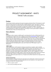
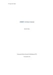
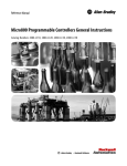
Høgskolen i Buskerud
Løsning til skriftlig eksamen i emnet
SESM3401 Styring av mekatroniske systemer
Eksamensdato: Mandag 8. desember 2008. Varighet: 3 timer. Vekt: 70%.
Hjelpemidler: Ingen trykte eller håndskrevne hjelpemidler. Kalkulator ikke
tillatt.
Kontakt under eksamen: 1. am. Finn Haugen (telefon 97019215)
Hvis du mener at det i en oppgave mangler forutsetninger for løsning, skal
du selv definere disse forutsetningene slik at du allikevel kan løse oppgaven.
1. (15% vekt i dette oppgavesettet) Den logiske funksjonen
y = (x1 AND x2 ) OR x3
(1)
kan realiseres med ladderdiagram som vist i figur 1 og med
x1
y
x2
x3
Figur 1:
funksjonsblokkdiagram som vist i figur 2.
x1
x2
&
y
x3
1
Figur 2:
2. (15%) Se figur 3.
3. (15%) Fra kompendiet: A timer function is similar to a clock which is
started (triggered) by a starting signal changing value from OFF to
ON. When a preset time has elapsed, the timer output is set to ON.
1
Set
Reset
Out
Out
Figur 3:
As an example, a timer can be used to implement a time-delayed
start of a motor. Another example is to control the ON-time of a
heater.
PLCs have a number of different timers in their functions library.
Figure 4 shows an example of a timer. (The example can be found in
a user’s manual of the GX IEC Developer programming tool of
Mitsubishi PLCs.) The timer parameters are as follows.
Inputs
Outputs
Timer1
x0
EN
Q
M0
T#1m10s25ms
PT
ET
D0
Figur 4:
• Input EN (enable) [boolean] starts or triggers the timer.
• Input PT (preset time) [time] is the (elapsed) time or time
delay before the timer output Q is set to ON. The time format
is a special data format used to represent time. In Figure the
PT value is 1 minute 10 second 25 milliseconds.
• Output Q (output1 ) [boolean] is the timer output. It gets value
ON when the elapsed time is larger than the preset time.
• Output ET (elapsed time) [time] is the continuously running
time.
Figure 5 shows a timing diagram which shows the behaviour of the
timer along a time axis. The timer operates as follows:
1
Q means output. The ideal symbol O for output is not used since it is too easily
misinterpreted as zero.
2
ON (1)
EN:
OFF (0)
1m10s25ms
ET:
0s
ON (1)
Q:
OFF (0)
Time:
t0
t1
t2
t3
Elapsed time is
PT=1m10s25ms
t4
Elapsed time is
less than PT
Figur 5:
• The timer starts when the input x0 at the EN input goes from
OFF to ON. As the timer starts, the ET output increases
continuously from the initial value of 0 seconds. In this example,
the ET time value is stored in the data register D0 which is a
general register or memory cell where a value can be stored for
use in subsequent programming expressions.
• When the ET time has become larger than the PT (preset time)
value the boolean output Q is set to ON. In this example, the
value of Q is stored in memory cell M0 which is a general
memory cell where a boolean value can be stored for use in
subsequent programming expressions.
• If EN goes from ON to OFF, ET is reset to zero.
4. (15%) Transferfunksjonen for motor med sensor (prosessen) er
H(s) =
K
Ts + 1
(2)
der K og T har kjente verdier. Det er spesifisert at
reguleringssystemets responstid TC skal være omtrent lik T . Får da
3
ihht. Skogestads tabell:
Kp =
T
T
1
=
=
KTC
KT
K
Ti = min[T, 1.44TC ] = min[T, 1.44T ] = T
(3)
(4)
5. (25%) Sekvesiell styring av en batch-prosess (fra kompendiet
benyttet i emnet): Figure 6 shows a simple batch process. The tank
Figur 6: A batch process to be controlled by sequential control
is filled with water. The water is then heated and stirred2 , and finally
the heated water is discharged from the tank. The control signals are
• u_valve_in (boolean, i.e. having value TRUE or FALSE, or ON
or OFF)
• u_valve_out (boolean)
• u_motor (boolean)
• u_heat (continuous having any value between 0% and 100%)
2
The motor is assumed to ensure homogenuous thermal conditions in the water in the
tank.
4
The measurements are
• Temperature T of the water in the tank
• Level h of the water in the tank
In the exam you are asked to draw a state diagram of the control
system. The state diagram will be identical to the SFC (Sequential
Function Chart) shown in Figure 7. E.g. the states are S0, S1, etc.
The actions are A0_1, A0_2, etc. The transitions are T0_1, T1_2,
etc.
S0
(Init)
Transition T0_1:
Start_Batch_Button == TRUE;
S1
Actions:
A0_1: u_valve_in := OFF;
A0_2: u_valve_out := OFF;
A0_3: u_motor := OFF;
A0_4: PID_auto := OFF;
A1_1: u_valve_in := ON;
(Filling)
T1_2: Level >= Level_High;
S2
A2_1:
A2_2:
A2_3:
A2_4:
(Heat. Stirr.)
u_valve_in := OFF;
u_motor := ON;
PID_auto := ON;
Timer_Enable := ON;
T2_3: Timer_Value >= 10000 s;
S3
A3_1: u_valve_out := ON;
A3_2: u_motor := OFF;
(Emptying)
T3_4: Level <= Level_Low;
S4
A4_1: u_valve_out := OFF;
A4_2: PID_auto := OFF;
(Pause)
T4_5: Finish_Button == ON;
T4_1: Restart_Button == ON;
S5
(End)
Figur 7:
6. (5%) Posisjonen er den tidsintegrerte av hastigheten. I s-planet
5
uttrykkes tidsintegrasjon med divisjon med s. Transferfunksjonen fra
pådraget u til posisjonen x blir da
K
(T s + 1) s
7. (10%) HIL-simulering: Fysisk reguleringsutstyr (kalt ECU —
Electronic Control Unit) regulerer en simulert prosess.
HIL-simulering kan være nyttig for testing og opplæring.
6
(5)