1
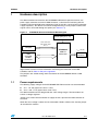
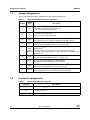
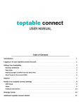
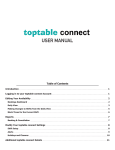
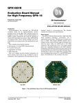
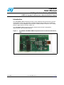
UM0284 User Manual Getting started with the STUSB03E USB full-speed transceiver demonstration board Introduction The STUSB03E USB full-speed transceiver is fully compliant with the universal serial bus specification revision 2.0. It provides a complete physical layer solution for any USB full speed device. The STUSB03E connected with an USB controller is ideal for use in mobile phones, digital cameras, printers, PDAs, etc. The STUSB03E USB full-speed transceiver demonstration board is designed for demonstration and evaluation purposes. Figure 1. Assembled STUSB03E USB full-speed transceiver demonstration board PCB AM01731v1 June 2009 Doc ID 12664 Rev 2 1/11 www.st.com Contents UM0284 Contents 1 2 Hardware description . . . . . . . . . . . . . . . . . . . . . . . . . . . . . . . . . . . . . . . . 3 1.1 Power requirements . . . . . . . . . . . . . . . . . . . . . . . . . . . . . . . . . . . . . . . . . . 3 1.2 Jumper assignments . . . . . . . . . . . . . . . . . . . . . . . . . . . . . . . . . . . . . . . . . 4 1.3 Connector assignments . . . . . . . . . . . . . . . . . . . . . . . . . . . . . . . . . . . . . . . 4 1.4 Test points . . . . . . . . . . . . . . . . . . . . . . . . . . . . . . . . . . . . . . . . . . . . . . . . . 5 References . . . . . . . . . . . . . . . . . . . . . . . . . . . . . . . . . . . . . . . . . . . . . . . . . 6 Appendix A STUSB03E demonstration board schematic diagram . . . . . . . . . . . 7 Appendix B STUSB03E demonstration board components layout . . . . . . . . . . . 8 Appendix C STUSB03E demonstration board bill of materials . . . . . . . . . . . . . . 9 Revision history . . . . . . . . . . . . . . . . . . . . . . . . . . . . . . . . . . . . . . . . . . . . . . . . . . . . 10 2/11 Doc ID 12664 Rev 2 UM0284 1 Hardware description Hardware description The demonstration board contains the STUSB03E USB low/full speed transceiver, one power supply connector, one mini-B USB connector, a connector for interfacing with the controller and all required discrete components (pull-up resistors, serial resistors and power supply capacitors). The device can also be configured using a set of jumpers and the main signals can be accessed through test points (see Section 1.4). Figure 2. STUSB03E demonstration board block diagram Power pins (VBUS, VIF) SPD, CON, SUS, OE#, VBUS, RSEL RPULL-UP Jumpers STUSB03E USB FS Transceiver USB Controller Header Connector VBUS, DP, DM Mini-B connector The 'USB controller header connector' makes it possible to connect a USB controller or any digital control system. For more information concerning the connection of the USB controller, refer to Table 4: CN2 pin assignments. The jumpers also enable testing and measurement of the STUSB03E without a USB controller. 1.1 Power requirements The following supply voltages for the STUSB03E USB FS transceiver are recommended: ● VIF = 1.6 - 3.6 (typical VIF value is 1.8 V) ● VBUS = 4.0 - 5.5 V (typical VBUS value is 5 V). The demonstration board is designed for the same voltage ranges. The board does not contain a voltage regulator. Jumper J3 is used to choose whether to supply the VBUS pin from the USB connector or from CN1. When the VBUS voltage is above VBUSDET threshold, LED D1 switches ON. Connect jumper J9 to enable this function. Doc ID 12664 Rev 2 3/11 Hardware description 1.2 UM0284 Jumper assignments Table 1 describes the jumper assignments of the demonstration board. Table 1. Demonstration board jumper assignments Jumper Related pin(s) J1 D+ Connected: connects a 1.5 kΩ pull-up resistor to the D+ data line. Must be connected in full-speed mode when RSEL = 0 Leave open when in low-speed mode. J2 D- Connected: connects a 1.5 kΩ pull-up resistor to the D- data line. Must be connected in low-speed mode. Leave open when in full-speed mode. J3 VBUS 1-2 connected: selects CN1 connector as 5 V VBUS voltage source. 2-3 connected: 5 V VBUS voltage is supplied by CN3 USB connector J4 SPD 1-2 connected: STUSB03E transceiver in low-speed mode(1) 2-3 connected: STUSB03E transceiver in full-speed mode J5 Description 1-2 connected: VPU pin in high impedance; data line pull-up resistor disconnected(1) CON, RSEL, 2-3 connected: VPU pin outputs 3.3 V ±10% (data line pull-up resistor SPD, VPU connected to internal LDO regulator output) when SPD = 1 and RSEL = 0 or when SPD = 0 J6 SUS 1-2 connected: STUSB03E transceiver active(1) 2-3 connected: STUSB03E transceiver in suspend mode J7 RSEL 1-2 connected: internal FS pull-up resistor disabled 2-3 connected: internal FS pull-up resistor enabled J8 OE# J9 VBUSDET 1-2 connected: STUSB03E transceiver in transmit mode(1) 2-3 connected: STUSB03E transceiver in receive mode Connected: enables the VBUS voltage detection LED. LED switches ON when voltage greater than the VBUSDET threshold is detected. 1. Leave this jumper open when controlling this function using an external USB controller connected to CN2. 1.3 Connector assignments Table 2. Demonstration board connectors Connector 4/11 Descriptions CN1 Power supply: VBUS, VIF and GND. Refer toTable 3 for pin assignments. CN2 Header connector for USB controller connection. Refer to Table 4 for USB controller connections. CN3 USB mini-B connector. Doc ID 12664 Rev 2 UM0284 Hardware description Table 3. CN1 pin assignments Pin number Description 1 VBUS – connect a 5 V supply voltage when powering VBUS pin from CN1 2 VIF – Interface supply voltage (1.6 V to 3.6 V) 3 Ground 4 Table 4. 1.4 CN2 pin assignments Pin number Description Pin number Description 1 VBUSDET 6 VM 2 SPD 7 RCV 3 GND 8 CON 4 VP 9 OE# 5 GND 10 SUS Test points Table 5. Test points Test point number Description 1 D+ data line 2 D- data line 3 VM signal 4 VP signal 5 RCV signal 6 VBUSDET signal Doc ID 12664 Rev 2 5/11 References 2 6/11 UM0284 References 1. STUSB03E datasheet 2. Universal serial bus specification 3. USB engineering change notice to USB specification revision 2.0. Doc ID 12664 Rev 2 Doc ID 12664 Rev 2 2 1 1" 2 * (%!$%28 #. #. * * * * * 6"53?#. 0 0 0 6)& 0 60 6- 353 #/. 2#6 30$ 6"$ 2#6 30$ 6- 60 605 /% $ $ 642- /% $5 $5 642- 3453"% 5 # 2 2 # 2 K * 2 K # * * 1# 1% $ ,%$ 6)& 6"$ 6"53 #/. 6)& '.$ 6"53 353 605 23%, 23%, 2 K $ $ 2 K * 0 # 0 6"53?#. 6"53 $ $ )$ '.$ 3($ 3($ Figure 3. 3($ 3($ Appendix A UM0284 STUSB03E demonstration board schematic diagram STUSB03E demonstration board schematic diagram Schematic diagram .OTASSEMBLED !-V 7/11 STUSB03E demonstration board components layout Appendix B Figure 4. UM0284 STUSB03E demonstration board components layout Demonstration board components layout !-V Resistors R5 and R6 and capacitors C3 and C4 can be added in order to simulate typical load conditions (Host/Hub side pull-down resistors and capacitive load). 8/11 Doc ID 12664 Rev 2 UM0284 STUSB03E demonstration board bill of materials Appendix C STUSB03E demonstration board bill of materials Table 6. Bill of materials Reference Part type Quantity Footprint U1 STUSB03E 1 QFN16(3x3) C1 4,7 µF 1 1210 C2 1 μF 1 1210 R1, R2 20 Ω ±1% 2 3518 R3, R4 1,5 kΩ ±1% 2 3518 R7 560 Ω 1 3518 R8 120 Ω 1 3518 J1, J2 Jumper 2 Through hole, pitch 2.54 mm J3-J8 Jumper 6 Through hole, pitch 2.54 mm J9 0 Ω bridge 1 0603 P1-P2 Header 1 2 Through hole, pitch 2.54 mm D1 KP-2012SRC-PRV 1 0805 Q1 2STR1230 1 SOT-23 CN1 Header 4 1 Through hole, pitch 2.54 mm CN2 Header 5x2 1 Through hole, pitch 2.54 mm CN3 MINI-B USB receptacle 1 USB mini-B, SMT Doc ID 12664 Rev 2 9/11 Revision history UM0284 Revision history Table 7. 10/11 Document revision history Date Revision Changes 18-Sept-2006 1 Initial release 04-Jun-2009 2 – Changed: Figure 1, 3 and 4 – Modified: Table 1, 6. Doc ID 12664 Rev 2 UM0284 Please Read Carefully: Information in this document is provided solely in connection with ST products. STMicroelectronics NV and its subsidiaries (“ST”) reserve the right to make changes, corrections, modifications or improvements, to this document, and the products and services described herein at any time, without notice. All ST products are sold pursuant to ST’s terms and conditions of sale. Purchasers are solely responsible for the choice, selection and use of the ST products and services described herein, and ST assumes no liability whatsoever relating to the choice, selection or use of the ST products and services described herein. No license, express or implied, by estoppel or otherwise, to any intellectual property rights is granted under this document. If any part of this document refers to any third party products or services it shall not be deemed a license grant by ST for the use of such third party products or services, or any intellectual property contained therein or considered as a warranty covering the use in any manner whatsoever of such third party products or services or any intellectual property contained therein. UNLESS OTHERWISE SET FORTH IN ST’S TERMS AND CONDITIONS OF SALE ST DISCLAIMS ANY EXPRESS OR IMPLIED WARRANTY WITH RESPECT TO THE USE AND/OR SALE OF ST PRODUCTS INCLUDING WITHOUT LIMITATION IMPLIED WARRANTIES OF MERCHANTABILITY, FITNESS FOR A PARTICULAR PURPOSE (AND THEIR EQUIVALENTS UNDER THE LAWS OF ANY JURISDICTION), OR INFRINGEMENT OF ANY PATENT, COPYRIGHT OR OTHER INTELLECTUAL PROPERTY RIGHT. UNLESS EXPRESSLY APPROVED IN WRITING BY AN AUTHORIZED ST REPRESENTATIVE, ST PRODUCTS ARE NOT RECOMMENDED, AUTHORIZED OR WARRANTED FOR USE IN MILITARY, AIR CRAFT, SPACE, LIFE SAVING, OR LIFE SUSTAINING APPLICATIONS, NOR IN PRODUCTS OR SYSTEMS WHERE FAILURE OR MALFUNCTION MAY RESULT IN PERSONAL INJURY, DEATH, OR SEVERE PROPERTY OR ENVIRONMENTAL DAMAGE. ST PRODUCTS WHICH ARE NOT SPECIFIED AS "AUTOMOTIVE GRADE" MAY ONLY BE USED IN AUTOMOTIVE APPLICATIONS AT USER’S OWN RISK. Resale of ST products with provisions different from the statements and/or technical features set forth in this document shall immediately void any warranty granted by ST for the ST product or service described herein and shall not create or extend in any manner whatsoever, any liability of ST. ST and the ST logo are trademarks or registered trademarks of ST in various countries. Information in this document supersedes and replaces all information previously supplied. The ST logo is a registered trademark of STMicroelectronics. All other names are the property of their respective owners. © 2009 STMicroelectronics - All rights reserved STMicroelectronics group of companies Australia - Belgium - Brazil - Canada - China - Czech Republic - Finland - France - Germany - Hong Kong - India - Israel - Italy - Japan Malaysia - Malta - Morocco - Philippines - Singapore - Spain - Sweden - Switzerland - United Kingdom - United States of America www.st.com Doc ID 12664 Rev 2 11/11