1
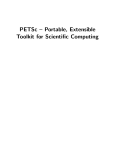
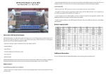
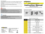
Kitty User's Guide
This guide will serve as a general user's manual for all Kitty based mods. As of this
writing, there is a Kitty model for MadCatz Tournament Edition FightStick, and one for
the Hori VLX arcade stick.
Installation will not be covered in this guide, only use. Please follow these links to get to
the installation guide for your model of Kitty:
TE Kitty Installation Guide:
http://www.godlikecontrols.com/download/kitty/TEKitty_Install.pdf
VLX Kitty Installation Guide:
http://www.godlikecontrols.com/download/kitty/VLXKitty_Install.pdf
Overview
The Kitty mod is an after market add-on to a specific Xbox360 arcade sticks. The Kitty
allows your arcade stick to work on many different video game consoles more than it
can normally support out of the box. Wherever possible, all of the additional consoles
work just as if they were originally built for it, with proper support of Turbo functions
and any other features built into the stick. Futhermore, any additional perks possible,
such as on-the-fly button remapping, have been added.
Much of the credit for this guide should go to Shoryuken.com forum guru rtdzign, who
has collected the RJ45 pinout pictures and creation guides, blantantly copied here with
permission. Much credit is also due to Shoryuken.com forum tech Gummowned who
wrote the Kitty.exe frontend that makes updating the firmware much easier for everyone
to use.
Updating the Firmware
The Kitty boards have upgradable firmwares. The most recent firmware revisions should
always be available at the following URLs:
TE Kitty Firmware: http://www.godlikecontrols.com/download/kitty/tekitty.zip
VLX Kitty Firmware: http://www.godlikecontrols.com/download/kitty/vlxkitty.zip
Download and extract the zip file to a directory you can easily get to. Run the Kitty.exe
executable.
Click the button “Update Firmware”.
Browse through the Open window that pops up and select the HEX file that was in the
zip. Click the 'Open' button once you have it selected.
Updating the Firmware, Cont'd
A new window will pop up, instructing you to hold down the Guide button and plug the
USB cable into your PC. Do as it says. If you have a TE Kitty, make sure the slide
switch is set to 'Unlocked'.
When you see the upper left and lower right LEDs around the Guide button light up on
your stick, press 'Ok'.
You will likely see this screen pop up asking for permission to run the update program.
Click 'Yes'.
Updating the Firmware, Cont'd
You should see a DOS window pop up with text, showing the progress of the firmware
updating steps. Once it has completed, the window will disappear, and your joystick will
exit the bootloader mode and go back to normal joystick mode. If the window quickly
flashes and disappears before you can read any text, then the updating program was not
able to see the joystick. Check the lights around the Guide button to be sure it is in
bootloader mode and try again. The full process should take around 30-45 seconds, most
of it in the 'U2IO flash programming:' portion.
Your firmware is now up to date.
Changing the USB Name
There is a specific name associated with the Kitty stick that you sometimes see when
plugging the stick into a PC, and always see in the Game Controllers applet of the
Control Panel.
This string can be changed to personalize the name of your arcade stick. To do this,
download and extract the firmware for your model of Kitty, just like in the “Updating
the Firmware' steps above.
Once the zip file is extracted, run the 'Kitty' application. Click on 'Open HEX', select the
hex file that was included in the zip, and click 'Open'.
Changing the USB Name, Cont'd
After the hex file has been loaded, you will see the USB string in that hex file displayed.
You can then edit the USB String box to be anything you might like to name the stick.
Once the USB String field is set to your liking, click on 'Save HEX' to save the modified
hex file. Select a new name for your custom firmware, and click 'Save' for save your
copy.
Once your custom firmware has been saved, follow the 'Updating your Firmware'
directions to flash your Kitty with the custom firmware. Just make sure to select your
saved firmware after pressing 'Update Firmware'.
On-The-Fly Button Remapping
All of the consoles natively supported by the Kitty have the ability to remap the buttons
however you would like. Please note, the Xbox360 is NOT a natively supported console;
the Xbox360 buttons are NOT able to be remapped. Each of the different supported
consoles stores its button configuration separately, so that changing the button mapping
for, say, the NES console, has no effect on the button mappings for PC/PS3 console.
You're only able to change the button mappings for the console you're connected to.
Please take a moment to verify that the stick and buttons work on the console before
trying to remap them. Next, write down or print out the small chart at the bottom of that
console's page later in this guide. You will need the chart showing the mapping number
and button for that console, like this one for the Sega Saturn:
Remapping
number
Saturn Button
1
X
2
A
3
Y
4
B
5
Z
6
C
7
L
8
R
To enter the remapping mode, hold down the Guide and Turbo for a full 45 seconds.
You'll notice that your directional stick will no longer register on the console, nor on the
LEDs surrounding the Guide button. That's how you'll know that you've successfully
entered the button remapping mode. Release the Guide and Turbo buttons.
Now your stick is waiting for you to tell it what buttons should activate the Saturn's X
button, because it's the first in the list, “remapping number 1”. Press and release the
button you want to activate X. Then press and release the button you want to activate A,
and again for button Y, B, Z, C, L, and R. Once you release that last button, your stick
returns to normal operation, and you'll see the directional stick goes back to displaying
the direction on the Guide LEDs and all of the buttons working properly on the console
again. The settings were automatically saved, and will retain that mapping until you
repeat the steps to remap the buttons again.
On-The-Fly Button Remapping, Advanced
Most consoles have a 'control' type set of buttons, like the classic Start and Select. In
some cases, you can assign these to buttons, but no matter what, the Start and Select
buttons on your stick will still activate these as normal. The functions assigned to the
Start and Select/Back buttons cannot be unassigned.
When your stick is waiting for you to assign a button, you are not limited to just one
physical button. If you press and release multiple buttons at the same time, ALL of them
will activate that button on the console. If you do not want any physical button to
activate that console's button, press and release Select/Back and the remapping will go
to the next virtual button.
Even if there are far less buttons on the console than the 8 usually used, the remapping
will not end until 8 buttons have been assigned or skipped with the Select/Back button.
Let's take for example the NES. If you're on the NES, which has four mappable buttons.
Remapping NES Button
number
1
A
2
B
3
Select
4
Start
5
6
7
8
If you wanted to make your top four buttons activate A, and the bottom four buttons
activate B, and did not want anything except the Start and Select/Back buttons to
activate the NES Select and Start, then you would hold down Guide and Turbo to get
into remapping mode, and release. Press and release the top four buttons so that they get
assigned to 'A'. Press and release the bottom four buttons so that they get assigned to 'B'.
Then press and release the Select/Back button six times, so that the remapping numbers
3-8 all get set to unassigned.
Protip: For most semi-modern consoles, going into button remapping mode and
press/releasing the first punch button, first kick button, second punch button, second
kick button, etc. will set the button mapping to the generally accepted Street Fighter
default.
RJ-45 Connection
The Kitty boards come with an RJ45 jack that can be used for plugging in cords to use
your arcade stick on other, non-USB based game consoles. Using an RJ45 jack on your
arcade stick is entirely optional; you can use the Kitty on PC/PS3 and Xbox360 just fine
using the USB cord that is built into your arcade stick and ignore the RJ45 jack entirely.
However, if you want to play on the older, non-USB based consoles that the Kitty
supports, you must use the RJ45 jack and make a console cord for the systems you want
to play on.
Each console uses a different connector for plugging into that console. The Kitty board
knows how to talk to these consoles, but you still need to make a cable so your stick can
plug into the console. Each console cord has different numbers or wires and types of
connectors. This section will attempt to show you how to properly crimp an RJ45 end
onto each of the different supported console extension cords. You will require a
controller cord either from a sacrificed controller, or from a controller extension cord for
that system.
In addition to the cord itself, you will also need an RJ45 crimp end along with a
crimping tool. Both of these are available at most quality computer stores. These are the
exact same ends and tools needed for crimping Ethernet networking cables. It is also
recommended that you have a sharp hobby knife for removing insulation, and a 'boot'
cover to help make everything look clean.
Making an RJ45 cable
Use the cable guide in the following pages to determine which wire of your console
cable should go to which pin on the RJ45 end. This step will show you how to properly
crimp an RJ45 end using a USB console cable. Each console cable will have different
wires of different colors going to different pins on the RJ45 end. Make sure the wires
and pins used match what is listed in the 'Console Specifics' section for that console.
First, cut the end of the wire as far as possible from the end that plugs into your console.
Any pair of wire cutters can do the job. Use a hobby knife or similar tool to remove
about 1/2” (12mm) of the outer insulation of the cord. If there are any thin, woven wires
in the cable for shielding, trim them back to where the outer insulation ends. We need
those well out of the way. Then slide a boot over the cord and move it down out of the
way.
Cable with insulation trimmed back.
Trimmed cable with boot slid on.
Making an RJ45 cable, Cont'd
Take your RJ45 plug and shove the console cable's wires into the correct pins. For the
USB cord used in this example, the black wire (ground) goes to pin 1, the white wire
(D-) into pin 5, the green wire (D+) into pin 6, and the red wire (VCC) into pin 8.
Take a moment to verify that all of the wires are full inserted into each pin hole. You'll
notice that the thicker, still insulation cord is under the rectangular bar at the base of the
RJ45 plug. That bar will be crimped down to hold onto the thicker cord. If your thin
wires do not reach all of the way to the end of the RJ45 plug, pull it out, and remove a
little more of the outer insulation so it does. If the thin wires are too long, the thicker,
insulatied cable will not be fully under that rectangular piece, and the plug could easily
slide off; trim some of the end of the thin wires off so the insulated section goes in as far
as possible. Once you are sure each of the wires is in their place, use the crimping tool to
crimp the pins onto the thin wires, and the rectangular piece onto the this section of cord.
Slide the boot up to cover the end of the plug, and test it out on a console.
Console Specifics – USB
A USB cable can be used for using your Kitty stick on a computer, Xbox360, or
Playstation 3 console. It can also be used for updating the firmware of your Kitty board.
Since most folks will be using the dedicated USB cable that came with their stick,
making an RJ45->USB cable is entirely optional.
USB is one of the few console cables available that you can rely on the coloring of the
wires to guide you. Use the following guide to learn which color wire goes into which
RJ45 pin.
Wire Color/Purpose RJ45 Pin Number
Black - Ground
1
White - D-
5
Green - D+
6
Red - VCC
8
The same button mappings for Playstation 3 use are used when on a computer, so
remapping one will also remap the other. The 'computer button number' is the number
that lights up in the Game Controllers applet of the control panel with that button is
pressed; the same numbers are used for the controller setup of most computer games.
Remapping number
Playstation 3 button name Computer button number
1
Square
1
2
X
2
3
Triangle
4
4
Circle
3
5
R1
6
6
R2
8
7
L1
5
8
L2
7
When using a TE Kitty, the stick will control the Left analog stick, D-pad, or Right
analog stick based on the setting of the LS/DP/RS slide switch. For all other Kitties,
stick controls the Dpad and Left analog stick by default. Hold down Select/Back when
plugging in for Left Stick only. Hold down Start when plugging in for Dpad only.
Console Specifics – PSX/PS2
The Playstation cord is one of the most popular cords to use with a Kitty, but it is also
the most complicated. There are no wire colors to work off of, 9 pins on the console end,
and we need a very specific seven of those nine wires. This is the easiest cord to mess
up, so take your time, use a multimeter to be certain that each PSX pin uses the color of
wire you think it does, and take your time putting the wires into the RJ45 pins. If it
doesn't work, clip the RJ45 end off, recheck the PSX pin to color mapping you wrote
down, and try again.
RJ45 Pin
PSX Pin
1
GND
2
CLK
3
CMD
4
DAT
5
ATT
7
ACK
8
VCC
N/C stands for 'Not
Connected'
Remapping number Playstation/Playstation 2
button name
1
Square
2
X
3
Triangle
4
Circle
5
R1
6
R2
7
L1
8
L2
Playstation support emulates the original PSX digital control pad, like almost every
other Playstation arcade stick. As such, there are no analog sticks nor analog stick
'clicks' to report to the console.
Console Specifics – Dreamcast
The Dreamcast cord only contains five wires, making this console cord a moderately
simple one to use.
RJ45 Pin
Dreamcast Pin
1
3
3
4
4
5
7
1
8
2
Remapping number Dreamcast button name
1
X
2
A
3
Y
4
B
5
Z
6
C
7
L
8
R
Console Specifics – Gamecube
The Gamecube cord requires only three wires, making it the simplest of all console
cords to make.
RJ45 Pin
Gamecube Pin
1
3
7
2
8
1
The Gamecube support includes two different extended modes for Smash Brothers play.
The button descriptions below are for the default mode when the stick is plugged in
normally. Gamecube support has a single mapping, so remapping the default Gamecube
layout will also affect the Smash Brothers modes, and visa versa.
Remapping Gamecube Smash Brothers Mode – Smash Brothers Mode – Advanced
number
button
Basic (Button 3 and
(Button 5 and Button 6 held on
name
Button 4 held on plugin) plugin)
1
Y
A (Attack/Tilt)
A (Attack/Tilt)
2
B
Shield
Shield
3
X
B (Special Attack)
B (Special Attack)
4
A
5
L Trigger
6
R Trigger
7
(Not Used)
8
(Not Used)
Jump
Jump
Run
Lock (locks Lstick direction in
place, and stick is reported as Cstick until released.)
Console Specifics – Xbox (Original)
The Xbox original cord uses 5 wires, and is almost identical to other USB devices. The
Xbox cords are pretty reliable about following a set color code, so if you see yellow, red,
white, green, and black wires, feel free to use the colors when crimping the RJ45 end.
We'll only be using four of the five wires; trim the yellow wire very short so there's no
chance of it touching any other wires or exposed shielding wires.
RJ45 Pin
Xbox Pin
Expected
wire color
1
4
Black
5
2
White
6
3
Green
8
1
Red
Not used.
5
Yellow
Remapping Xbox button
number
name
Home+Button
combination
activates:
1
X
Left stick 'click'
2
A
Right stick 'click'
3
Y
4
B
5
White
6
Black
7
L Trigger
8
R Trigger
Console Specifics – NES
RJ45 Pin
NES Pin
1
1
2
2
4
4
7
3
8
7
Famicom should be possible by using the
equivalent pins, but is untested and
undocumented.
Remapping NES Button
number
1
A
2
B
3
Select
4
Start
5
6
7
8
Console Specifics – SNES
RJ45 Pin
SNES Pin
1
1
4
4
7
5
2
6
8
7
Super Famicom uses identical ends and
pins.
Remapping SNES Button
number
1
Y
2
B
3
X
4
A
5
L
6
R
7
8
Console Specifics – TurboGrafx-16/PC-Engine
RJ45 Pin
TG-16/PC-Engine Pin
1
8
2
2
3
3
4
4
5
7
6
6
7
5
8
1
The internal workings of PC-Engine and
TG-16 controllers are identical, but they
use different types of end connectors. The
TG-16 uses a larger DIN-8 connector,
while the PC-Engine uses a Mini-DIN-8
connector. Make sure to use the pin
numbers from the image for your particular
end!
When connected directly to a TG-16 or PC-Engine, the stick will only function as a
standard 2 button gamepad. When connected through a Multi-Tap, pressing the
Home/Guide button will toggle between Two button and Six Button modes.
Remapping
number
TG-16/PC-Engine
Button (Direct, or
Multi-Tap Two
Button mode)
TG-16/PC-Engine
Button (Through
Multi-Tap, Six Button
mode)
1
II
IV
2
I
III
3
Select
V
4
Run
II
5
VI
6
I
7
Select
8
Run
Console Specifics – Sega Saturn
Remapping
number
Saturn Button
1
X
2
A
3
Y
4
B
5
Z
6
C
7
L
8
R
RJ45 Pin
Saturn Pin
1
9
2
3
3
2
4
8
5
4
6
5
7
7
8
1
Console Specifics – 3DO
3DO support on the Kitty is limited to only when the Kitty is the only controller hooked
up to the console. It will not work properly when at the end of a daisy chain of other
controllers, nor can other controllers daisy chain off of it.
Remapping
number
3DO Button
1
L
2
A
3
P (Play/Pause)
4
B
5
R
6
C
7
Stop
8
RJ45 Pin
3DO Pin
1
1
2
7
4
9
7
6
8
2
Version notes:
8/6/11 – v1.0 USB, PSX, DC console information.
9/5/11 – v1.1 Initial release . Continued addition of console information, and button
remapping.
9/5/11 – v1.2 Typo corrections