1
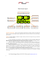
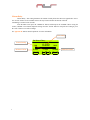
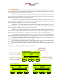
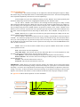
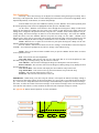
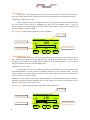
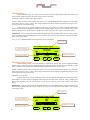
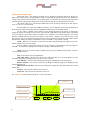
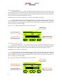
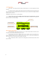
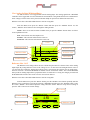
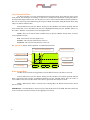
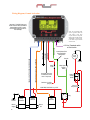
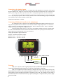
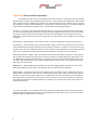
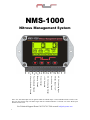
NMS-1000
Nitrous Management System
1 2 3
4 5 6
7 8 9
0-5 Volt, Analog Input
Tbrake Input, +12V
Activation, Ground
0-5 Volt, Analog Output
+12V Switched
Timer Output
Battery Ground
Fuel Solenoid Ground
Nitrous Solenoid Ground
Note—the Activation Input will be ignored while the Tbrake Input +12V(Transbrake/Clutch switch) is ON.
This way the Nitrous ramp will NOT begin until the Clutch/Transbrake is released even if the Wide Open
Throttle switch is ON.
For Technical Support Please Call 334-741-7100 or email [email protected]
1
Main Screen Layout
Nitrous Percent
Analog In
F
U
E
L
N
O
X
V-OUT
Analog Out
Fuel Percent
0.0
V-IN
0.00
Setup1
0 -OFF-
TIMER
SETUP NITROUS TIMER
Setup Menu
Controller options
Nitrous Menu
Nitrous/Fuel Setup
Main Timer Count
Current Setup
Activation Status
DATA
Timer Menu
Timer Setup
Data Menu
View Logged Data
Important Information - Must use Static Suppression Ignition Wires with this Controller. The NMS-1000
Nitrous Controller contains High Frequency Digital Electronics and will NOT function correctly without Suppression Wires!
Caution - Do NOT submerge Controller in liquid or directly wash unit with liquid of any type! (Do NOT
spray when washing vehicle!)
It is the responsibility of the purchaser to follow all guidelines and safety procedures supplied with
this product and any other manufactures product used with this product. It is also the responsibility of the purchaser to determine compatibility of this device with the vehicle and other components.
NLR, LLC assumes no responsibility for damages resulting from accident, improper installation, misuse, abuse, improper operation, lack of reasonable care, or all previously stated reasons due to incompatibility
with other manufacturer's products.
NLR, LLC assumes no responsibility or liability for damages incurred from the use of products manufactured or sold by NLR, LLC on vehicles used for competition racing. NLR, LLC neither recommends nor
approves the use of products manufactured or sold by NLR, LLC on vehicles which may be driven on public
highways or roads, and assumes no responsibility for damages incurred from such use.
It is the purchaser’s responsibility to check the state and local laws pertaining to the use of Nitrous
Oxide for racing applications. NLR, LLC does not recommend nor condone the use of its products for illegal
street racing.
For Technical Support Please Call 334-741-7100 or email [email protected]
2
Table of Contents
3
Setup Menu
Current Setup
Pulse Frequency
Hold and Wait
Main Timer
Fuel Trim Option
Help Option
Factory Reset
Terminal Strip Pin Out
Display Contrast
About NMS-1000
Page 4
Page 4
Page 4
Page 5
Page 5
Page 6
Page 6
Page 6
Page 6
Page 6
Nitrous Menu
Nitrous Delay
Nitrous Quick Setup
Nitrous Graph Setup
Fuel Graph Setup
Fuel Advance
Wideband Disable Volt
Wideband Delay
Wideband Enable Percent
Analog Out Graph Setup
Resume Start Percent
Resume Percent Per Pulse
Page 7
Page 8
Page 9
Page 10
Page 11
Page 11
Page 12
Page 12
Page 13
Page 14
Page 14
Timer Menu
Timer Delay
Timer Hold & Wait Option
Page 15
Page 15
Data Menu
View Analog In Data
Reference Line 1 & 2
View Nitrous/Fuel Data
Erase Logged Data
Page 16
Page 16
Page 17
Page 17
Installation Instructions
Wiring Diagram, Ground Activation
Connecting to the Analog Output
Connecting a Wideband Controller to Analog In
Page 18
Page 19
Page 19
Warranty Information
Warranty
Page 19
Appendix A, Pulse Frequency Detailed Explanation
Appendix B, Nitrous & Fuel Operation
Appendix C, Wideband Disable Feature Explained
Page 20
Page 21
Page 22
Current Setup
There are 3 Data Setups available. All user settings will be saved when selecting a New Data Setup
from the list. This way multiple User Setups can be stored and recalled at a later time. Example - you have a
Setup that is working well, you decide that you would like to try a few different settings. You could then Select
and Copy all current Setup Data to a New Setup and make changes without loosing the original setup.
From the Main screen press the “SETUP” button, press the “ENTER” button to select the Current
Setup menu. Using the “UP”, “DOWN” arrow buttons select the desired Setup and press “ENTER”. You will
then be prompted to copy the Current Setup to the new Setup selected. If you choose “YES” the current setup
will be copied to the new Setup selected.
NOTE—When asked to make a selection from a “Message Box” the default selection will be chosen
after 20 seconds.
Pulse Frequency
Pulse Frequency - This setting determines the number of times per second that the solenoids pulse. A
lower setting generally will provide a more linear power delivery. A lower setting allows lower starting percentages to be used also.
The correct setup will be different depending on the type of solenoids and bottle pressure used. Testing is the only way to determine the best frequency for each application.
NOTE—When changing the pulse frequency the current Nitrous Setup will be time altered. Be sure to
check the Nitrous and Fuel Settings after a Frequency change!
From the Main screen press the “SETUP” button, press the “DOWN” arrow button to highlight the
Pulse Frequency menu selection and then press the “ENTER” button. Using the “UP”,”DOWN” buttons selected the desired Pulse Frequency setting. Press “ENTER” to select the new setting or press “BACK” to exit
with no change.
See Appendix A “Pulse Frequency Detailed Explanation” for more information.
Hold and Wait
Hold & Wait Option - This setting allows the Progressive system to Hold & Wait when the Activation
signal is removed. Example - the throttle is lifted due to wheel spin or ? This allows the Progressive system to
resume at the point where the throttle was lifted.
NOTE—If this option is OFF the Progressive system and All Timers will reset each time the Activation is removed.
From the Main screen press the “SETUP” button, press the “DOWN” arrow button repeatedly until
the Hold & Wait menu selection is highlighted and then press the “ENTER” button. Press the “YES” or “NO”
button to change the current selection. If the “NO” button is pressed no change will be made.
NOTE—When asked to make a selection from a “Message Box” the default selection will be chosen
after 20 seconds.
4
Main Timer
Main Timeout - This setting controls the Main Timeout period in seconds. This controls the total time
elapsed before a System Timeout occurs. This limits the total amount of time the solenoids can be On if the
Activation signal is never removed. This setting also allows the system to be used with Hold & Wait option and
the Progressive Timers will reset after the Timeout Period has elapsed and the Activation signal is removed.
This enables a Reset without powering the unit down.
From the Main screen press the “SETUP” button, press the “DOWN” arrow button repeatedly until
the Main Timer menu selection is highlighted and then press the “ENTER” button. Using the
“LEFT”,”RIGHT” arrow buttons adjust the setting. Press the “SAVE” button to accept the new setting or press
the “ESC” button to exit with no change.
New Setting
Set Main Timeout...
Current Setting
Minimum Value
MIN
30
MAX
0.0
20
20
300
ESC
<
>
Maximum Value
SAVE
Fuel Trim Option
WARNING - This setting controls the Fuel Trim. This setting allows the Fuel Percentage to be set
Less than the Nitrous. Use this setting with great caution!
This setting controls the total Percentage the Fuel may be set less than the Nitrous. Example—a setting of 25 would allow the Fuel percent to be 25% less than the Nitrous.
Valid Range is 0% to 100% in 1% Increments.
From the Main screen press the “SETUP” button, press the “DOWN” arrow button repeatedly until
the Fuel Trim Option menu selection is highlighted and then press the “ENTER” button. Using the
“LEFT”,”RIGHT” arrow buttons adjust the setting. Press the “SAVE” button to accept the new setting or press
the “ESC” button to exit with no change.
See Appendix B “Nitrous & Fuel Operation” for more information.
New Setting
Set Fuel Trim Option...
Current Setting
Minimum Value
MIN
5
MAX
0.0
0
0
100
ESC
5
<
>
SAVE
Maximum Value
Help Option
Use this setting to turn the Automatic Help feature ON/OFF. When this feature is ON you will be
prompted to view Help text for each setting when you are making Menu selections.
From the Main screen press the “SETUP” button, press the “DOWN” arrow button repeatedly until
the Help menu selection is highlighted and then press the “ENTER” button. Press the “YES” or “NO” button to
change the current selection. If the “NO” button is pressed no change will be made.
NOTE—When asked to make a selection from a “Message Box” the default selection will be chosen
after 20 seconds.
Factory Reset
Factory Reset - Selecting this option will return ALL Settings to the original Factory settings.
From the Main screen press the “SETUP” button, press the “DOWN” arrow button repeatedly until
the Factory Reset menu selection is highlighted and then press the “ENTER” button. Press the “YES”,“NO”, or
“CANCEL” button to change the current selection. If the “NO” or “CANCEL” button is pressed no change will
be made.
NOTE—When asked to make a selection from a “Message Box” the default selection will be chosen
after 20 seconds.
Terminal Strip Pinout
Use this selection to display the Terminal Strip Pinout.
From the Main screen press the “SETUP” button, press the “DOWN” arrow button repeatedly until
the Terminal Strip Pinout menu selection is highlighted and then press the “ENTER” button. Press the
“BACK” button to exit.
Display Contrast
Use this Setting to adjust the LCD Display contrast.
From the Main screen press the “SETUP” button, press the “DOWN” arrow button repeatedly until
the Display Contrast menu selection is highlighted and then press the “ENTER” button. Using the
“LEFT”,”RIGHT” arrow buttons adjust the setting. Press the “SAVE” button to accept the new setting or press
the “ESC” button to exit with no change.
New Setting
LCD Contrast...
Current Setting
Minimum Value
MIN
5
MAX
0.0
0
5
10
ESC
<
>
Maximum Value
SAVE
About NMS-1000
This selection displays the current operating system version and the software build date.
From the Main screen press the “SETUP” button, press the “DOWN” arrow button repeatedly until
the About NMS-1000 menu selection is highlighted and then press the “ENTER” button. Press the “BACK”
button to exit.
6
Nitrous Delay
Nitrous Delay - This setting determines he amount of Delay before the Nitrous is applied after Activation. A Fuel Advance is also available so the Fuel may be started before the Nitrous if desired.
Valid Range is 0.000 to 9.990 seconds.
From the Main screen press the “NITROUS” button, and then press the “ENTER” button. Using the
“LEFT”,”RIGHT” arrow buttons adjust the setting. Press the “SAVE” button to accept the new setting or press
the “ESC” button to exit with no change.
See Appendix B “Nitrous & Fuel Operation” for more information.
New Setting
Set Nitrous Delay...
Current Setting
Minimum Value
MIN
0.200
MAX
0.000
0.0
0.000
9.990
ESC
7
<
>
SAVE
Maximum Value
Nitrous Quick Setup
Quick Setup - Use this selection to do Quick Progressive setups. This feature allows the Nitrous to be
setup using a Start Percent, Final Percent, and a Build Time. For advanced Nitrous and Fuel ramps use the Nitrous Graph Setup and the Fuel Graph Setup menu selections.
NOTE—This selection is provided so that Quick and Easy Nitrous Power Ramps can be created. This
selection has limited user adjustment of the power ramp and fuel delivery. Please see the Nitrous Graph Setup
and Fuel Graph Setup menu selections for Advanced control.
Start Percent - This setting determines the Nitrous Starting percentage. The Start Percent can be less
than or greater than the Final Percent setting. If the Start percent is greater than the Final percent the ramp will
progress backwards. Valid Range is 10% to 100% in 1% Increments.
Final Percent - This setting determines the Nitrous Final percentage. The Final Percent can be less
than or greater than the Start Percent setting. If the Start percent is greater than the Final percent the ramp will
progress backwards. Valid Range is 10% to 100% in 1% Increments.
Build Time - This setting determines the time it takes for the Nitrous to ramp from the Start Percent to
the Final Percent settings. A Short build time will make the Nitrous Power Ramp more aggressive and a longer
Build Time will make it less aggressive. Valid Range is .200 to 9.900 seconds in .100 second Increments.
From the Main screen press the “NITROUS” button, press the “DOWN” arrow button to highlight the
Nitrous Quick Setup menu selection and then press the “ENTER” button. Use the “UP”,”DOWN” arrow buttons to select the desired setting to change and press the “ENTER” button.
Using the “LEFT”,”RIGHT” arrow buttons to adjust the setting. Press the “SAVE” button to accept
the new setting or press the “ESC” button to exit with no change.
After all settings have been determined press the “BACK” button, press the “YES” button to accept
the New Nitrous Pwer Ramp settings or “NO” to exit without saving the new settings.
When a New Nitrous Power Ramp is Saved the Nitrous and Fuel Tables are updated with the Quick
Setup Data.
See Appendix B “Nitrous & Fuel Operation” for more information.
New Setting
Set Start Percent...
Current Setting
Minimum Value
MIN
20
MAX
0.0
10
20
100
ESC
Set Final Percent...
>
SAVE
Set Build Time...
MIN
90
MAX
MIN
2.000
MAX
0.0
10
90
100
0.200
0.0
2.000
9.900
SAVE
ESC
ESC
8
<
Maximum Value
<
>
<
>
SAVE
Nitrous Graph Setup
Nitrous Setup - The Nitrous Percentage can be adjusted for each Pulse during the Progressive Ramp.
This is done using a 2-D Graph Editor. Please see Basic Editing Instructions below. The Fuel Percentage/Ramp
can be adjusted independently of the Nitrous (see Fuel Graph Setup).
From the Main screen press the “NITROUS” button, press the “DOWN” arrow button repeatedly until
the Nitrous Graph Setup menu selection is highlighted and then press the “ENTER” button.
Use the “LEFT”, “RIGHT” arrow buttons to move through the Nitrous Progressive Ramp. To Edit
and/or change the Nitrous Progressive Ramp move the cursor to the position to Edit and press the “EDIT” buton. The editing cursor will appear at the position selected. Using the “UP”, “DOWN” arrow buttons adjust the
new percentage setting. Press the “ENTER” button to accept the new setting. Use the “LEFT”, “RIGHT” arrow
buttons to move to the next set point. Each cursor position represents One pulse of the Nitrous Solenoid. Press
the “EDIT” button and adjust the Nitrous Percentage as outlined above. Press “ENTER” to accept the new setting.
NOTE—When the two set points are more than one pulse apart the Progressive Ramp will be automatically filled in between the set points.
Press the “MENU” button to Exit and/or Save the new setting(s). From the Menu select Exit and press
“ENTER”. You will then be prompted to Save the new settings or Exit without saving. After the Nitrous data is
saved you will be prompted to copy the Nitrous setup to the Fuel setup. Note—Some of the Fuel percentages
may be adjusted even if the Nitrous Data is NOT copied to the Fuel setup. Please read the IMPORTANT note
below for more information.
NOTE—There are several selections available when you pres the “MENU” button. Please see below
for an explanation of each.
Exit—This selection exits the Graph Editor.
Clear Edit Points—This selection will clear any Edit Points that are set in the Graph Screen. This
does NOT change any Percentage setting, only the Cursor is removed.
View Old Data—This selection will display the Progressive Ramp that is stored in memory.
Restore Old Data—This selection will restore the Progressive Ramp settings if any Editing has been
done and NOT Saved.
Zoom In—This selection will Zoom the X-Axis in.
Zoom Out—This selection will Zoom the X-Axis out.
IMPORTANT—When Saving a new Nitrous setup the software will compare the new Nitrous Percentage
settings to the current Fuel Percentage settings. If the Fuel Percentage for a given pulse is Less than the Nitrous
Percentage - Fuel Trim (See Setup Menu) the Fuel Percentage will automatically be adjusted to Nitrous Percentage - Fuel Trim. To allow full control of the Fuel Percentage versus Nitrous Percentage set the Fuel Trim
Option to 100%. Do this with caution as a Lean condition can and will result if improper settings are entered!
See Appendix B “Nitrous & Fuel Operation” for more information.
Progressive Ramp
Maximum Value
100
Cursor
Minimum Value
Current Percentage
9
10
PERCENT 25
MENU
<
>
TIME 1.650
EDIT
Current Time
Fuel Graph Setup
Fuel Setup - The Fuel Percentage can be adjusted for each Pulse during the Progressive Ramp. This is
done using a 2-D Graph Editor. Please see Basic Editing Instructions below. The Fuel Percentage/Ramp can be
adjusted independently of the Nitrous (see Nitrous Graph Setup).
From the Main screen press the “NITROUS” button, press the “DOWN” arrow button repeatedly until
the Fuel Graph Setup menu selection is highlighted and then press the “ENTER” button.
Use the “LEFT”, “RIGHT” arrow buttons to move through the Fuel Progressive Ramp. To Edit and/or
change the Fuel Progressive Ramp move the cursor to the position to Edit and press the “EDIT” buton. The
editing cursor will appear at the position selected. Using the “UP”, “DOWN” arrow buttons adjust the new percentage setting. The Fuel Percentage can NOT be set less than Nitrous Percentage - Fuel Trim (See IMPORTANT note below). Press the “ENTER” button to accept the new setting. Use the “LEFT”, “RIGHT” arrow
buttons to move to the next set point. Each cursor position represents One pulse of the Fuel Solenoid. Press the
“EDIT” button and adjust the Fuel Percentage as outlined above. Press “ENTER” to accept the new setting.
NOTE—When the two set points are more than one pulse apart the Progressive Ramp will be automatically filled in between the set points.
Press the “MENU” button to Exit and/or Save the new setting(s). From the Menu select Exit and press
“ENTER”. You will then be prompted to Save the new settings or Exit without saving.
NOTE—There are several selections available when you pres the “MENU” button. Please see below
for an explanation of each.
Exit—This selection exits the Graph Editor.
Clear Edit Points—This selection will clear any Edit Points that are set in the Graph Screen. This
does NOT change any Percentage setting, only the Cursor is removed.
View Old Data—This selection will display the Progressive Ramp that is stored in memory.
Restore Old Data—This selection will restore the Progressive Ramp settings if any Editing has been
done and NOT Saved.
View Nitrous Data—This selection will display the current Nitrous setup on the screen.
Copy Nitrous Data—This selection will copy the current Nitrous setup to the Fuel setup.
Zoom In—This selection will Zoom the X-Axis in.
Zoom Out—This selection will Zoom the X-Axis out.
IMPORTANT—When Saving a new Fuel setup the software will compare the Nitrous Percentage settings to
the current Fuel Percentage settings. If the Fuel Percentage for a given pulse is Less than the Nitrous Percentage - Fuel Trim (See Setup Menu) the Fuel Percentage will automatically be adjusted to Nitrous Percentage Fuel Trim. To allow full control of the Fuel Percentage versus Nitrous Percentage set the Fuel Trim Option to
100%. Do this with caution as a Lean condition can and will result if improper settings are entered!
See Appendix B “Nitrous & Fuel Operation” for more information.
Progressive Ramp
Maximum Value
100
Cursor
Minimum Value
Current Percentage
10
10
PERCENT 25
MENU
<
>
TIME 1.650
EDIT
Current Time
Fuel Advance
Fuel Advance - This setting allows the Fuel to start before the Nitrous. With the Fuel operating at a
lower pressure this allows the proper amount of fuel to be delivered with the Nitrous upon Initial Activation.
Valid Range is 0.000 to 9.999 second.
From the Main screen press the “NITROUS” button, press the “DOWN” arrow button repeatedly until
the Fuel Advance menu selection is highlighted and then press the “ENTER” button. Using the
“LEFT”,”RIGHT” arrow buttons adjust the setting. Press the “SAVE” button to accept the new setting or press
the “ESC” button to exit with no change.
See Appendix B “Nitrous & Fuel Operation” for more information.
New Setting
Set Fuel Advance...
Current Setting
Minimum Value
MIN
.025
MAX
.000
0.0
.000
.250
ESC
<
>
Maximum Value
SAVE
Wideband Disable Volt
Wideband Disable Voltage - This setting determines the Input Voltage Level that turns OFF the Nitrous. This allows the output from a Wide Band Oxygen Controller to turn OFF the Nitrous system if the engine goes Lean. A setting of 0.0 will Dis-Able this function. You will need to determine the correct voltage
using the manual that came with your Wide Band system.
Valid Range is 0.0 to 5.0 volts.
From the Main screen press the “NITROUS” button, press the “DOWN” arrow button repeatedly until
the Wideband Disable Volt menu selection is highlighted and then press the “ENTER” button. Using the
“LEFT”,”RIGHT” arrow buttons adjust the setting. Press the “SAVE” button to accept the new setting or press
the “ESC” button to exit with no change.
IMPORTANT—This setting is used with the “Wideband Delay” and “Wideband Enable Percent” settings to
determine if the Nitrous should be disabled because of a lean condition. ALL of three of these parameters work
together to allow greater control of this feature.
See Appendix C “Wideband Disable Feature Explained” for more information.
New Setting
Set Wideband Disable Volt...
Current Setting
Minimum Value
MIN
2.50
MAX
0.00
0.0
0.00
5.00
ESC
11
<
>
SAVE
Maximum Value
Wideband Delay
Wideband Disable Delay - This setting controls the amount of time the Analog Input Voltage must be above the
Nitrous Disable Voltage. This allows the system to filter out short Lean spikes.
Valid Range is 0.000 to 1.000 Second in .001 Increments.
Example - When the Nitrous is first activated the air-fuel is 14 to 1 and the Wideband Disable Voltage is set to turn off the
nitrous if the system is 12.8 to 1 or above. This setting would allow the Nitrous and Fuel to begin flowing and get to an airfuel ratio that is below the disable setting.
From the Main screen press the “NITROUS” button, press the “DOWN” arrow button repeatedly until the Wideband Delay menu selection is highlighted and then press the “ENTER” button. Using the “LEFT”,”RIGHT” arrow buttons
adjust the setting. Press the “SAVE” button to accept the new setting or press the “ESC” button to exit with no change.
IMPORTANT—This setting is used with the “Wideband Disable Volt” and “Wideband Enable Percent” settings to determine if the Nitrous should be disabled because of a lean condition. ALL of three of these parameters work together to allow
greater control of this feature.
See Appendix C “Wideband Disable Feature Explained” for more information.
New Setting
Set Wideband Disable Delay
Current Setting
Minimum Value
MIN
0.500
MAX
0.000
0.0
0.500
1.000
ESC
<
>
Maximum Value
SAVE
Wideband Enable Percent
Wideband Enable Percent - This setting determines at what Nitrous Percent (Duty Cycle) the Wideband Disable
function is Active. When the progressive ramp first begins the system will not be at the 100% Nitrous air-fuel ratio. Use this
setting to determine at what Nitrous Percent the Wideband Nitrous Disable function becomes active.
Example - When the Nitrous is first activated the air-fuel is 14 to 1 and the Wideband Disable Voltage is set to turn off the
nitrous if the system is 12.8 to 1 or above. This setting would allow the Nitrous and Fuel to begin flowing and get to an airfuel ratio that is below the disable setting.
Valid Range is 10% to 100%
From the Main screen press the “NITROUS” button, press the “DOWN” arrow button repeatedly until the Wideband Enable Percent menu selection is highlighted and then press the “ENTER” button. Using the “LEFT”,”RIGHT” arrow
buttons adjust the setting. Press the “SAVE” button to accept the new setting or press the “ESC” button to exit with no
change.
IMPORTANT—This setting is used with the “Wideband Disable Volt” and “Wideband Delay” settings to determine if the
Nitrous should be disabled because of a lean condition. ALL of three of these parameters work together to allow greater
control of this feature.
New Setting
Set Wideband Enable Percent
Current Setting
Minimum Value
MIN
90
MAX
0.0
10
80
100
ESC
12
<
>
SAVE
Maximum Value
Analog Out Graph Setup
Analog Out Setup - The Analog Out Voltage can be adjusted for each Pulse during the Progressive
Ramp. This is done using a 2-D Graph Editor. Please see Basic Editing Instructions below. The Analog Out
voltage can be used for Data Recording or as an analog Input to a Electronic Fuel Injection controller. When
used with EFI the analog output voltage can be used to richen the fuel delivery during Nitrous Activation.
This output will be at 0.0 volt when the NMS-1000 is NOT Activated. Valid range for this output is
0.0 to 5.0 volts in .1 volt increments.
From the Main screen press the “NITROUS” button, press the “DOWN” arrow button repeatedly until
the Analog Out Graph Setup menu selection is highlighted and then press the “ENTER” button.
Use the “LEFT”, “RIGHT” arrow buttons to move through the Analog Out setings. To Edit and/or
change the Analog Out settings move the cursor to the position to Edit and press the “EDIT” buton. The editing
cursor will appear at the position selected. Using the “UP”, “DOWN” arrow buttons adjust the new setting.
Press the “ENTER” button to accept the new setting. Use the “LEFT”, “RIGHT” arrow buttons to move to the
next set point. Each cursor position represents One pulse of the Nitrous/Fuel Solenoid. Press the “EDIT” button
and adjust the Analog Out voltage as outlined above. Press “ENTER” to accept the new setting.
NOTE—When the two set points are more than one pulse apart the Analog Out voltage will be automatically filled in between the set points.
Press the “MENU” button to Exit and/or Save the new setting(s). From the Menu select Exit and press
“ENTER”. You will then be prompted to Save the new settings or Exit without saving.
NOTE—There are several selections available when you pres the “MENU” button. Please see below
for an explanation of each.
Exit—This selection exits the Graph Editor.
Clear Edit Points—This selection will clear any Edit Points that are set in the Graph Screen. This
does NOT change any Percentage setting, only the Cursor is removed.
View Old Data—This selection will display the Progressive Ramp that is stored in memory.
Restore Old Data—This selection will restore the Progressive Ramp settings if any Editing has been
done and NOT Saved.
Build From Nitrous Data—This selection will build an Analog Out data table based on the current
Nitrous Data.
Zoom In—This selection will Zoom the X-Axis in.
Zoom Out—This selection will Zoom the X-Axis out.
See Appendix B “Nitrous & Fuel Operation” for more information.
Analog Out
Maximum Value
5.0
Cursor
Minimum Value
Current Voltage
13
0.0
VOLTS 0.7
MENU
<
>
TIME 1.650
EDIT
Current Time
Resume Start Percent
Resume Start Percent - This setting determines the percent the Nitrous resumes at if the user has to lift
the throttle during Activation. This setting is only valid if the Hold And Wait option is ON. This setting is used
with the Resume Percent Per Pulse setting to build a Resume Ramp. If the Resume Start Percent is greater than
the current Nitrous percent the Resume Ramp is ignored.
Valid Range is 10% to 100% in 1% Increments. A setting of 100% disables this feature.
From the Main screen press the “NITROUS” button, press the “DOWN” arrow button repeatedly until
the Resume Start Percent menu selection is highlighted and then press the “ENTER” button. Using the
“LEFT”,”RIGHT” arrow buttons adjust the setting. Press the “SAVE” button to accept the new setting or press
the “ESC” button to exit with no change.
See Appendix B “Nitrous & Fuel Operation” for more information.
New Setting
Set Resume Start%...
Current Setting
Minimum Value
MIN
90
MAX
0.0
10
40
100
ESC
<
>
Maximum Value
SAVE
Resume Percent Per Pulse
Resume Percent Per Pulse - This setting determines the rate at which the Nitrous Resumes if the user
lifts the throttle during activation. This setting is used with the Resume Start Percent to build a Resume Ramp.
This allows the user to adjust how quick the Nitrous comes Back On if the Activation signal is removed.
Valid Range is 10% to 50% in 1% Increments.
From the Main screen press the “NITROUS” button, press the “DOWN” arrow button repeatedly until
the Resume Percent Per Pulse menu selection is highlighted and then press the “ENTER” button. Using the
“LEFT”,”RIGHT” arrow buttons adjust the setting. Press the “SAVE” button to accept the new setting or press
the “ESC” button to exit with no change.
See Appendix B “Nitrous & Fuel Operation” for more information.
New Setting
Set Resume% Per Pulse...
Current Setting
Minimum Value
MIN
25
MAX
0.0
10
10
50
ESC
14
<
>
SAVE
Maximum Value
+12V Timer Delay
Timer Delay - This setting controls the amount of Delay before the +12V Timer Output turns on after
activation.
If a setting of 0.000 is entered the Timer Output will turn ON with the First Pulse of the Nitrous Solenoid. This output can NOT be disabled and the user must remove any wires connected to the Output terminal to
disable any device connected
Valid Range is 0.000 to 9.990 in .01 second increments.
From the Main screen press the “TIMER” button and then press the “ENTER” button. Using the
“LEFT”,”RIGHT” arrow buttons adjust the setting. Press the “SAVE” button to accept the new setting or press
the “ESC” button to exit with no change.
New Setting
Set Timer Delay...
Current Setting
Minimum Value
MIN
1.000
MAX
0.000
0.0
1.000
9.990
ESC
<
>
Maximum Value
SAVE
Timer Hold & Wait Option
Timer Hold Option - This setting determines if the +12V Timer Output remains On when the Activation signal is removed and the Hold & Wait option is also on.
From the Main screen press the “TIMER” button, press the “DOWN” until the Timer Hold menu selection is highlighted and then press the “ENTER” button. Press the “YES” or “NO” button to change the current selection. If the “NO” button is pressed no change will be made.
NOTE—When asked to make a selection from a “Message Box” the default selection will be chosen
after 20 seconds.
15
View Analog In Data (Wideband Data)
Use this selection to view Logged Data from the Analog Input. The Analog signal from a Wideband
Controller can be logged and viewed to determine the Air Fuel Ratio. Using the Reference Line1 and Reference
Line2 voltages, reference lines can be placed on the Data Graph to represent user defined Air-Fuel ratios.
Reference Line1 has a short dash and Reference Line2 has a long dash.
From the Main screen press the “DATA” button and then press the “ENTER” button. Use the
“LEFT”, “RIGHT” arrow buttons to move through the Analog In Data.
NOTE—There are several selections available when you pres the “MENU” button. Please see below
for an explanation of each.
Exit—This selection exits the Graph Viewer.
Zoom In—This selection will Zoom the X-Axis in.
Zoom Out—This selection will Zoom the X-Axis out.
Cursor
Maximum Value
Analog Out
5.00
Reference Line1
Reference Line2
Minimum Value
Current Voltage
0.00
VOLT 2.0
MENU
<
TIME 4.5
EDIT
>
Current Time
Reference Line 1 & 2
The Reference Line settings allows the user to define the placement of a reference lines on the Analog
Input Graph. By setting Reference Line1 to the voltage of 14.7 Air Fuel ratio and setting Reference Line2 to
12.0 Air Fuel ratio voltage the Analog Input voltage can be viewed using the reference lines to quickly determine Air Fuel ratio. An external Wideband O2 monitor must be used for this feature. The external Wideband
must provide an Analog Output that is proportional to the recorded O2 level. Using the voltages provided with
the Wideband the reference lines can be set to the Air Fuel ratio desired.
Reference Line1 has a short dash and Reference Line2 has a long dash.
From the Main screen press the “DATA” button, press the “DOWN” arrow button repeatedly until the
Reference Line1 or Reference Line2 menu selection is highlighted and then press the “ENTER” button. Using
the “LEFT”,”RIGHT” arrow buttons adjust the setting. Press the “SAVE” button to accept the new setting or
press the “ESC” button to exit with no change.
New Setting
Set Reference Line1...
Current Setting
Minimum Value
MIN
2.50
MAX
0.00
0.0
2.50
5.00
ESC
16
<
>
SAVE
Maximum Value
View Nitrous/Fuel Data
Use these selections to view the Actual Nitrous/Fuel Percentage output. These data logs can be used to
check that the Activation Input is remaining on and also as a Tuning Aid. If the throttle is being lifted the Nitrous/Fuel Data Graph will show this. Also the data view can be used to tailor the Nitrous Resume parameters.
The user can enter setup values and then log the Progressive Ramp and simulate lifting the throttle while doing
a Dry Test (Nitrous and Fuel OFF).
From the Main screen press the “DATA” button, press the “DOWN” arrow button repeatedly until the
View Nitrous Data or View Fuel Data menu selection is highlighted and then press the “ENTER” button. Use
the “LEFT”, “RIGHT” arrow buttons to move through the Data.
NOTE—There are several selections available when you pres the “MENU” button. Please see below
for an explanation of each.
Exit—This selection exits the Graph Viewer.
Zoom In—This selection will Zoom the X-Axis in.
Zoom Out—This selection will Zoom the X-Axis out.
See Appendix B “Nitrous & Fuel Operation” for additional information.
Throttle lift, Resume Ramp
Maximum Value
100
Cursor
Minimum Value
Percentage
Nitrous/Fuel Percent
10
PERCENT 48
MENU
<
>
TIME 2.750
EDIT
Current Time
Erase Logged Data
Use this selection to Erase all Logged Data. Once the Data is Erased it can NOT be retrieved!
From the Main screen press the “DATA” button, press the “DOWN” arrow button repeatedly until the
Erase Logged Data menu selection is highlighted and then press the “ENTER” button. Press the “YES” or
“NO” button to Erase the saved data. If the “NO” button is pressed the data will not be erased.
NOTE—When asked to make a selection from a “Message Box” the default selection will be chosen
after 20 seconds.
IMPORTANT—The Data MUST be Erased to log new data and the Power to the NMS-1000 must remain ON
for 20 seconds after Activation in order for the logged data to be Saved.
17
Wiring Diagram, Ground Activation
Important - The NMS-1000 must
remain ON even when the Nitrous
Arming Switch is OFF in order
for the Data Logging function to
work correctly!
Note—the Activation Input
will be ignored while the
+12V Input is ON. This
way the Nitrous ramp will
NOT begin until the Clutch/
Transbrake is released even
if the Wide Open Throttle
switch is ON.
20GA GREEN
20GA RED
20GA GRAY
14GA BLACK
16GA ORANGE, FUEL SOLENOID GROUND
16GA BLUE, NITROUS SOLENOID GROUND
1 2 3 4 5 6 7 8 9
+12V from Transbrake switch
or Clutch switch.
Install Optional Fuel
Pressure Safety
Switch Here
Fuel
Pump
Ground
Battery
Ground
5 Amp
Fuse
Wide Open
Throttle
Switch
1amp Max. Use relay
if connected to more
than 1 Amp Load!
Nitrous
Arming
Switch
Switched +12 Volts
(Key On)
30 or 40
Amp Fuse
16GA RED, SOLENOID +12 VOLT
+12 Volts
87 87A
86
Relay
Battery
Ground
Nitrous
Supply
18
Nitrous
Safety
Solenoid
85
Nitrous
Solenoid
Fuel
Solenoid
Nitrous
Out
30
Connecting to the Analog Output
The Analog output can supply a 0-5 volt output that is fully adjustable for each Pulse of the Nitrous
Progressive Ramp. This voltage can be used as an Input to an Electronic Fuel Injection Unit to richen the fuel
delivery when using a Dry Nitrous System. Please refer to “Analog Out Graph Setup” for more information.
It is up to the user to determine compatibility of this feature with their EFI system and to determine the
correct setup for proper operation. There are many variables involved with determining a proper Fuel Map and
it is beyond the scope of this user manual to address this.
Analog Output Impedance is 1k Ohm.
Connecting a Wideband Controller to the Analog Input
The Analog Input can be connected to any Wideband O2 Module that outputs a signal in the 0-5 volt
range that corresponds to the Air Fuel Ratio. You will need to find the voltage output for 14.7 to 1 and set the
“Reference Line 1” (see Data Menu settings) to this value. Then set “Reference Line 2” to the Air Fuel Ratio
voltage you would like to target, for example 12.6 to 1
Using the Analog In Data Viewer you can see the Air Fuel Ratio without the need for a Laptop and/or
PC. This Air Fuel Ratio data can also be used to turn OFF the Nitrous if the system goes Lean. Please see the
Nitrous Menu Section and Appendix C for more information.
Analog Input Impedance approx 100k Ohm.
Example—Wideband Commander settings:
Reference Line 1 = 2.94 volts = 14.7 to 1
Reference Line 2 = 1.25 volts = 12.0 to 1
Example - Wideband Commander
White/Yellow
Analog
Output
Analog
Input
Ground
White/Green
Black/White
Warranty
NLR, LLC warrants to the original purchaser that the NMS-1000 shall be free from defects
in parts and workmanship under normal use for 90 days from the date of purchase.
NLR, LLC obligation under this warranty is limited to the repair or replacement of any component found to be defective when returned postpaid to NLR, LLC. The Controller must be returned
with evidence of place and date of purchase or warranty will be void. The warranty will not apply if
the NMS-1000 has been installed incorrectly, repaired, damaged, or tampered with by misuse, negligence or accident.
19
Appendix A, Pulse Frequency Detailed Explanation
The Pulse Frequency is the number of times per second (Hertz) the Solenoids are turned ON/OFF.
This Frequency can be adjusted to one of four values 12.5, 20, 25, and 40 pulses per second. Please Note that
special solenoids are required to operate correctly at 40 Hertz.
When the pulse frequency is changed the Nitrous and/or Fuel Progressive Ramps should be checked.
The reason for this is the way the NMS-1000 stores the data. For example a setting of 12.5 Hertz requires much
less data per second than a 40 Hertz setting.
When going from a lower frequency setting to the 40 Hertz frequency setting the Total Time in seconds for the Progressive Ramp is decreased. Please see the chart below for the total time for each frequency
setting. This change in time does NOT effect the Main Timer Timeout period in any way. The last Percentage
setting of the Progressive Ramp is used for the remainder on the Main Timer period. See Appendix B for more
information.
The best way to learn more about this feature is to change pulse frequency and then use the “Nitrous
Graph Setup” to navigate the Progressive Ramp and view the time change per pulse in the Graph Setup screen.
Pulse Frequency Time Chart
12.5 Hertz
20 Hertz
25 Hertz
40 Hertz
20
= 10 seconds
= 10 seconds
= 10 seconds
= 6.250 seconds
Appendix B, Nitrous and Fuel Operation
The NMS-1000 allows the user to adjust the Nitrous/Fuel delivery for each Pulse of the solenoids during the Progressive Ramp. This adjustability allows the user to tune for Rich/Lean conditions at different points
in the Progressive Ramp. Multiple precision timers are included to Delay the start of Nitrous delivery, Advance
the Fuel delivery, and to provide an additional +12 volt output to control external devices. A Resume Ramp has
been included so Throttle Lift transitions can be controlled and/or Gear change transitions.
Activation—The system is activated when either a Ground or +12V signal is present on the Activation terminals. Once activated the Main Timer begins counting down and is displayed on the main screen. If the Hold &
Wait option is ON the system timers will NOT reset if the Activation signal is removed (throttle lift). If the
Hold & Wait option is OFF the system will reset and start over each time the Activation signal is removed and
re-applied.
Nitrous Delay—If this function is set the Nitrous Timers will NOT begin until this Time Delay has expired.
Fuel Advance—After the Nitrous Delay has timed out this setting is checked. If a Fuel Advance time has been
set the Fuel Solenoids will begin operation before the Nitrous solenoids. For example if a lean spike was occurring the system could be programmed to deliver a 80% Fuel pulse .050 second before the first Nitrous solenoid
pulse. It is recommended to check nozzle flow and total volume flow to insure correct fuel delivery.
Nitrous/Fuel Progressive Ramp—Once activated and the Delay and Fuel Advance timers have expired the system will pulse the solenoids as programmed. The Nitrous and Fuel use independent data to allow greater control. When the End of the Progressive Ramp is reached the system will use the Last Percentage in the Progressive Ramp until the Main Timer expires. When the Main Timer is done the only way to Reset the system is to
remove the Activation Signal.
IMPORTANT—When the Hold & Wait option is ON the Data Logging function will NOT save the current
data until the Main Timer has expired. This allows up to 20 seconds of data to be captured.
Resume Ramp—This setting controls the Percentage that the system returns to after a throttle lift on the next
Solenoid Pulse. Example-the system is at 80% and the throttle is lifted and re-applied, if the Resume Start Percent was set at 50% the first pulse would be 40%. The Resume Ramp will increase at the rate of the Resume
Percent Per Pulse setting until the system returns to the Percentage it was at before the throttle lift. If the Fuel
and Analog Out settings are at a higher and/or lower setting they are scaled so they resume at the same rate as
the Nitrous Solenoids.
+12 Volt Timer Output—If a setting of 0.000 is entered the Timer Output will turn ON with the First Pulse of
the Nitrous Solenoid. This output can NOT be disabled and the user must remove any wires connected to the
Output terminal to disable any device connected.
21
Appendix C, Wideband Disable Feature Explained
The Wideband Disable feature allows the Nitrous/Fuel delivery to be suspended if a Lean condition is
detected. There are three settings that determine the sensitivity and conditions that must be met to disable the
system. There are many factors that determine the correct settings for individual application. Using the integrated data logging functions these settings can be determined. The Air Fuel Ratio can be viewed to determine
the amount of time it takes to reach the desired ratio. By using the Nitrous/Fuel Output data the user can determine if/when the system is disabled. For example, you go full throttle and activate the system. The throttle is
never lifted but in the Output Data you see that the Outputs were turned off. You can then view the Air Fuel
data and use this information together to change the Wideband Disable settings for correct operation.
Wideband Disable Volt—This setting determines that Voltage present on the Analog Input terminal that will
disable the system. The Wideband controller used to provide this signal must use a lower voltage to indicate a
rich condition and a higher voltage to indicate a lean condition. By using the information provided by the
Wideband controller manufacturer, the desired Air Fuel Ratio turn OFF point can determined.
Wideband Delay—This setting determines the amount of time the Analog Input must be equal to or above the
Wideband Disable Voltage before the outputs are disabled. This allows short duration lean spikes to be filtered
out and also allows time for the Nitrous and Fuel system to activate and get to the desired Air Fuel ratio. For
example the Air Fuel Ratio under normal operation is 14.7 to 1, when the system is first activated it takes x.xxx
amount of time for the Air Fuel Ratio to drop don to 12.0 to 1
Wideband Enable Percent—This setting determines the Percentage the Nitrous output must be at before the
system can be disabled. For example when you first activate the system and as the progressive ramp begins it is
set to run a Air Fuel Ratio of 13.0 to 1 and you have the system set to disable at 12.8 to 1. As the Nitrous Ramp
Progresses and reaches 80% and above the Air Fuel Ratio goes to 12.0 to 1. This would allow the leaner condition at the beginning of the Progressive Ramp only.
22