1
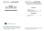
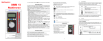
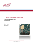
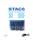
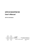
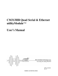
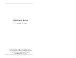
DM6854
Isolated Digital I/O dataModule
User’s Manual
ISO9001 and AS9100 Certified
BDM-610010032
Rev. B
DM6854 User’s Manual
RTD Embedded Technologies, Inc.
103 Innovation Blvd.
State College, PA 16803-0906
Phone: +1-814-234-8087
FAX: +1-814-234-5218
E-mail
[email protected]
[email protected]
web site
http://www.rtd.com
Copyright 1999-2010 RTD Embedded Technologies, Inc.
All rights reserved
The RTD Logo is a registered trademark of RTD Embedded Technologies. cpuModule and dataModule are
trademarks of RTD Embedded Technologies. PC/104 is a registered trademark of PC/104 Consortium. All other
trademarks appearing in this document are the property of their respective owners.
Page 2 of 33
DM6854 User’s Manual
Manual Revision History
Rev. A
New RTD USA Manual
Rev. B
RTD ISA ID added
Added AS9100 Information
Updated board photo to current PCB revision
Updated jumper diagrams to match
Added information on CN9
Replaced PC/104 connector pinout with a link to PC/104 Consortium
Corrected description of isolated input inversion
Added Dimension Drawing
Page 3 of 33
DM6854 User’s Manual
TABLE OF CONTENTS
CHAPTER 1
INTRODUCTION............................................................................................................................ 6
FEATURES...................................................................................................................................................................6
GENERAL PURPOSE DIGITAL I/O..................................................................................................................................6
ISOLATED DIGITAL INPUTS ..........................................................................................................................................6
ISOLATED DIGITAL OUTPUTS .......................................................................................................................................6
MECHANICAL DESCRIPTION ........................................................................................................................................6
CONNECTOR DESCRIPTION ..........................................................................................................................................7
WHAT COMES WITH YOUR BOARD .............................................................................................................................. 7
BOARD ACCESSORIES .................................................................................................................................................7
USING THIS MANUAL...................................................................................................................................................7
WHEN YOU NEED HELP ...............................................................................................................................................7
CHAPTER 2
CONFIGURING THE DATAMODULE .......................................................................................8
FACTORY-CONFIGURED JUMPER SETTINGS ................................................................................................................8
BASE ADDRESS (JP9) .................................................................................................................................................9
INTERRUPT CHANNEL (JP10) ....................................................................................................................................10
PD/PU PULL-UP OR PULL-DOWN RESISTOR SELECTION ............................................................................................ 10
IN1-IN8 OPTOCOUPLER INPUT RANGE .....................................................................................................................11
CHAPTER 3
INSTALLING THE DATAMODULE .........................................................................................12
RECOMMENDED PROCEDURE ...................................................................................................................................12
CHAPTER 4
CONNECTING THE DATAMODULE.......................................................................................13
FINDING PIN 1 OF CONNECTORS ............................................................................................................................... 13
ISOLATED I/O CONNECTIONS, JP15 & JP16 ..............................................................................................................13
EXPANSION INTERFACE CONNECTIONS, JP14 ...........................................................................................................14
PC/104 BUS CONNECTORS, CN1 AND CN2 ..............................................................................................................14
RESERVED CONNECTOR, CN9 ..................................................................................................................................14
CHAPTER 5
HARDWARE DESCRIPTION .....................................................................................................15
DIGITAL I/O, PROGRAMMABLE PERIPHERAL INTERFACE (PPI) .................................................................................15
ISOLATED OPTOCOUPLER INPUTS .............................................................................................................................. 16
Input Protection ...................................................................................................................................................16
Optocouplers .......................................................................................................................................................16
Input bit mask stage .............................................................................................................................................16
Input bit inverter stage ........................................................................................................................................16
ISOLATED OPTOCOUPLER OUTPUTS ........................................................................................................................... 17
Output data register.............................................................................................................................................17
Schmidt triggers ...................................................................................................................................................17
Optocouplers .......................................................................................................................................................17
TRIGGER OUTPUT......................................................................................................................................................17
INTERRUPTS.............................................................................................................................................................. 17
CHAPTER 6
BOARD OPERATION AND PROGRAMMING .......................................................................18
DEFINING THE I/O MAP ............................................................................................................................................18
BA+0 Digital input register (Write) ................................................................................................................18
BA+0 Digital inputs
(Read) ........................................................................................................................... 18
BA+1 Input mask register
(Read / Write) 0 after reset...................................................................................18
BA+2 Input inversion register (Read / Write) 0 after reset .............................................................................19
BA+3 Configuration / digital output register (Read / Write) 0 after reset ......................................................19
Page 4 of 33
DM6854 User’s Manual
BA+4 PPI Port A
(Read/Write) ......................................................................................................................19
BA+5 PPI Port B
(Read/Write) .....................................................................................................................19
BA+6 PPI Port C
(Read/Write) ......................................................................................................................20
BA+7 PPI Control Byte
(Write only) ............................................................................................................20
BA + 400h/BA + 401h RTD ID Data (read only, 8-bit or 16-bit) .......................................................................21
BA + 402h RTD ID Reset Pointer (read only, 8-bit only) ...................................................................................21
RTD ID Data Read Indexes .................................................................................................................................21
PROGRAMMING THE DM6854HR ............................................................................................................................. 21
Clearing and setting bits in an I/O port ...............................................................................................................22
Initializing the 8255 PPI......................................................................................................................................22
Isolated digital input programming .....................................................................................................................22
Software controlled direct read ........................................................................................................................22
Interrupt driven read upon change in bits ........................................................................................................23
Isolated digital output programming ...................................................................................................................23
Trigger output programming ............................................................................................................................... 23
Interrupts ............................................................................................................................................................. 23
What is an interrupt? ........................................................................................................................................23
Interrupt request lines ......................................................................................................................................24
8259 Programmable Interrupt Controller .........................................................................................................24
Interrupt Mask Register (IMR) ........................................................................................................................24
End-of-Interrupt (EOI) Command ...................................................................................................................24
What exactly happens when an interrupt occurs? ............................................................................................ 24
Using Interrupt in your Program ......................................................................................................................25
Writing an Interrupt Service Routine (ISR) .....................................................................................................25
Saving the Startup Interrupt Mask Register (IMR) and interrupt vector .......................................................... 26
Common Interrupt mistakes ............................................................................................................................. 27
Example of Interrupt vector table setup in C-code: .........................................................................................27
CHAPTER 7
SPECIFICATIONS........................................................................................................................29
GENERAL SPECIFICATIONS ........................................................................................................................................29
Interface ............................................................................................................................................................... 29
Digital I/O (non isolated) ....................................................................................................................................29
Digital inputs (isolated) .......................................................................................................................................29
Digital outputs (isolated) .....................................................................................................................................29
Connectors ........................................................................................................................................................... 29
DC CHARACTERISTICS..............................................................................................................................................30
DIMENSION DRAWING ..............................................................................................................................................31
CHAPTER 8
RETURN POLICY AND WARRANTY ......................................................................................32
RETURN POLICY .......................................................................................................................................................32
LIMITED WARRANTY ................................................................................................................................................32
Page 5 of 33
DM6854 User’s Manual
Chapter 1 INTRODUCTION
This user's manual describes the operation of the DM5854HR/DM6854HR Isolated Digital
Interface board.
Features
8 channel-by-channel isolated digital inputs with masking modes
4 Optocoupled digital outputs with open collector configuration, 30V range
24 non isolated TTL/CMOS compatible 8255-based digital I/O lines
Optional Pull-up or Pull-down resistors
Software enabled interrupts XT and AT interrupts available
Single +5V operation
Support for direct PC/104 interface with RTD dataModules®
XT (DM5854HR) and AT (DM6854HR) boards available
PC/104 compliant
RTD IDAN compatible
The following paragraphs briefly describe the major features of the DM6854HR. A more detailed
discussion is included in Chapter 5 (Hardware description) and in Chapter 6 (Board operation and
programming. The board setup is described in Chapter 2 (Configuring the dataModule).
General purpose digital I/O
The DM6854HR board has 24 8255-based TTL/CMOS compatible general purpose digital I/O
lines which can be directly interfaced with external devices or signals to interface to
alphanumerical displays, sense switch closures, trigger digital events, or activate solid-state relays.
These lines may be pulled down or pulled up or pulled down with 10K Ohm resistor networks.
Installation procedures will be described later in this manual.
Isolated digital inputs
Eight optocoupler inputs may be used to connect high voltage signals to a computer. Eight
channel-by-channel jumper configurable input ranges are available: +5V, +12V and +24V. The
optocoupler inputs have a reverse voltage protection diode across the input. This enables ACsignals to be connected to the isolated optocoupler inputs. This input diode also acts as a rectifier.
The programmable functions of the DM6854HR enable input masking and input pattern
recognition with interrupts. This relieves the host computer from processor capacity consuming
input polling.
Isolated digital outputs
Four open collector optocoupler outputs may be used to directly drive loads such as switches or
relays with voltages up to 30V DC.
Mechanical description
The DM6854HR is designed on a PC/104 form factor. An easy mechanical interface to both
PC/104 and PC/104-Plus systems can be achieved. Stack your PC/104 compatible computer
Page 6 of 33
DM6854 User’s Manual
directly on the DM6854HR using the onboard mounting holes. A dimension drawing with
connector locations is provided in Chapter 7.
Connector description
There is a 50 pin digital interface connectors on the DM6854HR to directly interface to the nonisolated 8255-based digital I/O signals. The signal definition of this connector is compatible with
the digital PC/104 dataModules manufactured by RTD.
Isolated outputs and inputs are connected to the DM6854HR by either a screw terminal discrete
wire connector, or with a 50-pin flat ribbon cable header connector. Use this type of interface
connector with a TB50 screw terminal block. Please consult the factory for more details on
different connector options.
What comes with your board
You receive the following items in your DM6854HR package:
DM6854HR Isolated digital interface module
Companion CD
Notes:
Latest software and drivers can be downloaded from our website.
If any item is missing or damaged, please contact RTD Embedded Technologies.
Board accessories
Several software and hardware accessories are available for the DM6854. Call your distributor for
more information on these accessories and for help in choosing the best items to support your
control system,
Application software and drivers
Hardware accessories such as IDAN aluminum enclosure systems. For more information
in IDAN please visit our websites at www.rtd.com.
Power Supplies
Terminal Adapter Board (TB50)
Using this manual
This manual is intended to help you install your new DM6854HR card and get it running quickly,
while also providing enough detail about the board and its functions so that you can enjoy
maximum use of its features even in the most demanding applications.
When you need help
This manual and all the example programs will provide you with enough information to fully
utilize all the features on this board. If you have any problems installing or using this board,
contact our Technical Support Department (814) 234-8087 during EST business hours, or send an
Email to [email protected]. When sending an Email request, please include your company's
name and address, your name, your telephone number, and a brief description of the problem.
Page 7 of 33
DM6854 User’s Manual
Chapter 2 CONFIGURING THE DATAMODULE
The following sections contain information on configuring the dataModule. Please read this entire
section before attempting to use the dataModule. The DM6854HR Isolated digital I/O board has
jumper settings that you can change to suit your application and I/O configuration setup.
Factory-Configured Jumper Settings
Table 2.1 illustrates the factory jumper setting for the DM6854HR. Figure 2.1 shows the board
layout and the locations of the jumpers. The following paragraphs explain how to change the
factory jumper settings to suit your specific application.
Table 2.1: Factory Default Jumper Settings
Jumper Name
BASE (JP9)
IRQ (JP10)
PD/PU
IN1-8
Description
Base Address
Interrupt Selection
Pullup or Pulldown for PPI Ports
Input Range for Isolated input 1-8
Number of Jumpers
5
12 (11+1)
3-terminal (4x)
3 (8x)
Factory Default
0x300
IRQ5, G
Pulldown
+24V
Figure 2.1: Board layout showing jumper locations
Page 8 of 33
DM6854 User’s Manual
Base Address (JP9)
(Factory setting: 300h)
The most common cause of failure when you are first setting up your module is address contention.
Some of your computers I/O space is already occupied by other internal I/O devices and expansion
boards. When the DM6854HR attempts to use its reserved I/O addresses already used by another
peripheral device erratic performance may occur and data read from the board may be corrupted.
To avoid this problem make sure you set up the base address first using the jumpers marked
"BASE" which let you choose from 32 different I/O addresses in your computers I/O map. Should
the factory installed setting of 300H be unusable for your system configuration, you may change
this setting to another using the options illustrated in Table 2.2. The table shows the jumper
settings and their corresponding I/O address in values hexadecimal and decimal. Make sure you
verify the correct location of the base address jumpers
Table 2.2: Base Address Jumper Settings
Base Address
Hex / (Decimal)
200/(512)
210/(528)
220/(544)
230/(560)
240/(576)
250/(592)
260/(608)
270/(624)
280/(640)
290/(656)
2A0/(672)
2B0/(688)
2C0/(704)
2D0/(720)
2E0/(736)
2F0/(752)
Jumper Settings
A8 – A4
00000
00001
00010
00011
00100
00101
00110
00111
01000
01001
01010
01011
01100
01101
01110
01111
Base Address
Hex / (Decimal)
300/(768)
310/(784)
320/(800)
330/(816)
340/(832)
350/(848)
360/(864)
370/(880)
380/(896)
390/(912)
3A0/(928)
3B0/(944)
3C0/(960)
3D0/(976)
3E0/(992)
3F0/(1008)
Jumper Settings
A8 – A4
10000
10001
10010
10011
10100
10101
10110
10111
11000
11001
11010
11011
11100
11101
11110
11111
Figure 2.2: Base Address jumper block (A4 to top, A8 to bottom; open = 0, closed = 1)
Page 9 of 33
DM6854 User’s Manual
Interrupt channel (JP10)
(Factory setting: IRQ5, G)
The header connector, shown on Figure 2.3 lets you connect the board interrupt to one of the 6
interrupt channels available on the XT/AT-bus. The ―G‖ setting installs a pull-down resistor on
the selected interrupt. The ―G‖ jumper is used to share an IRQ line between multiple devices.
Figure 2.3: Interrupt Selection Jumpers
Note: There must be exactly one ―G‖ jumper installed on any interrupt line.
The interrupt is caused by an external trigger event that has transferred the storage latch data to the
output latch of the isolated digital output stage.
PD/PU Pull-up or Pull-down resistor selection
(Factory setting: PA, PB and PC pulled ―Low‖)
The 8255 programmable digital I/O interface provides 24 TTL/CMOS compatible lines which can
be interfaced with external devices. These lines are divided into three groups: eight Port A lines,
eight Port B lines and eight Port C lines. You can connect pull-up or pull-down resistor networks
for ports A, B and C. There is a separate jumper for the upper four lines of Port C, and one for the
lower four lines. You may want to pull lines up for connection with switches. This will pull the
lines high if the switch is disconnected. Or you may want to pull lines down for connection to
relays which control turning motors on or off. The port A, B, and C lines of the 8255
programmable digital I/O interface are set as inputs after reset. This can cause the external devices
connected to these lines to operate erratically. Pulling these lines down, when the board is powered
up the lines will not be active before the 8255 is initialized. Figure 2.4 shows both Ports A, B and
C set in the Pull-down configuration.
Figure 2.4: Pull-up and Pull-down jumpers for Ports A, B and C.
Page 10 of 33
DM6854 User’s Manual
IN1-IN8 Optocoupler Input Range
(Factory setting: +24V range)
The Optocoupler inputs can be jumper configured for different input ranges. Each channel can be
set for a different range. The different ranges use different current limiting resistors at the
optocoupler diode input. Make sure you set the range correctly since overloading the optocoupler
with over current may cause permanent damage to the device. All the channels are set in a similar
manner. Figure 2.5 illustrates one channel set for a 24V-level input signal. The jumper topmost
toward the spring loaded connectors selects +24V input range, the middle position +12V and the
bottom most (toward the center of the board) +5V.
The optocoupler forward current is 0.13 mA for switching.
Figure 2.5: Optocoupler Input Range Jumpers set for 24V input range
Page 11 of 33
DM6854 User’s Manual
Chapter 3 INSTALLING THE DATAMODULE
Recommended Procedure
We recommend you follow the procedure below to ensure that stacking of the modules does not
damage connectors or electronics.
Turn off power to the PC/104 system or stack.
Select and install standoffs to properly position the dataModule on the PC/104 stack.
Touch a grounded metal part of the stack to discharge any buildup of static electricity.
Remove the dataModule from its anti-static bag.
Verify the jumper settings of the dataModule.
Check that keying pins in the PC/104 bus connector are properly positioned.
Hold the dataModule by its edges and orient it so the bus connector pins line up with the
matching connector on the stack.
Gently and evenly press the dataModule onto the PC/104 stack.
CAUTION: Do not force the module onto the stack! Wiggling the module or applying too
much force may damage it. If the module does not readily press into place,
remove it, check for bent pins or out-of-place keying pins, and try again.
Page 12 of 33
DM6854 User’s Manual
Chapter 4 CONNECTING THE DATAMODULE
The following sections describe connectors of the dataModule.
Finding Pin 1 of Connectors
A white area silk-screened on the PC board indicates the pin 1 end of connectors. A square solder
pad visible on the bottom of the PC board also indicates it.
Please make certain you have correctly identified pin 1 of a connector before you connect to it and
attempt to use the dataModule.
Isolated I/O connections, JP15 & JP16
The pin assignments for the isolated I/O are shown in Table 4.1. The DM6854 is available with
either a terminal block connection, or a 48 pin header connection. In the 48 pin header
configuration, each column of the header is connected to the same signal, i.e. pin 1 and 2 are both
IN1+.
Pin 1 is to the left side of the connector (when board is oriented as in Figure 2.1).
ALL SIGNALS ARE ISOLATED
Table 4.1: Isolated I/O Pin Assignments
Terminal Block Pin
1
2
3
4
5
6
7
8
9
10
11
12
13
14
15
16
17
18
19
20
21
22
23
24
Header Pin
1,2
3,4
5,6
7,8
9,10
11,12
13,14
15,16
17,18
19,20
21,22
23,24
25,26
27,28
29,30
31,32
33,34
35,36
37,38
39,40
41,42
43,44
45,46
47,48
Description
IN1+
IN1IN2+
IN2IN3+
IN3IN4+
IN4IN5+
IN5IN6+
IN6IN7+
IN7IN8+
IN8OUT1_COLLECTOR
OUT1_EMITTER
OUT2_COLLECTOR
OUT2_EMITTER
OUT3_COLLECTOR
OUT3_EMITTER
OUT4_COLLECTOR
OUT4_EMITTER
Page 13 of 33
DM6854 User’s Manual
Expansion Interface Connections, JP14
Figure 2-4 shows the 50-pin expansion interface connector layout of the DM6854HR. This
connector is used to interface to the non-isolated 8255 based digital I/O signals.
Table 4.2: 50-pin expansion interface connector pinout
Pin
Description
Description
Pin
1
3
5
7
9
11
13
15
17
19
21
23
25
27
29
31
33
35
37
39
41
43
45
47
49
Port_C(0)
Port_C(1)
Port_C(2)
Port_C(3)
Port_C(4)
Port_C(5)
Port_C(6)
Port_C(7)
Port_B(0)
Port_B(1)
Port_B(2)
Port_B(3)
Port_B(4)
Port_B(5)
Port_B(6)
Port_B(7)
Port_A(0)
Port_A(1)
Port_A(2)
Port_A(3)
Port_A(4)
Port_A(5)
Port_A(6)
Port_A(7)
+5V(fused)
Ext_Trigger(Output)
GND
GND
GND
GND
GND
GND
GND
GND
GND
GND
GND
GND
GND
GND
GND
GND
GND
GND
GND
GND
GND
GND
GND
GND
2
4
6
8
10
12
14
16
18
20
22
24
26
28
30
32
34
36
38
40
42
44
46
48
50
PC/104 Bus Connectors, CN1 and CN2
Connectors CN1 and CN2 provide PC/104 bus connections. CN1 carries XT bus signals, and CN2
carries additional signals for the AT bus. The signals on CN1 and CN2 conform to the IEEE P966
standard for the PC/104 bus. The PC/104 connector pinout may be found at www.pc104.org.
Note:
Two locations on the bus have mechanical keying pins to help prevent misconnection
of the PC/104 bus. These keying pins are a part of the PC/104 standard, and we
strongly recommend you leave them in place.
If you have other modules without keying pins, we suggest you modify them to
include keying.
Reserved Connector, CN9
CN9 is reserved for factory use. Nothing should be attached to this connector.
Page 14 of 33
DM6854 User’s Manual
Chapter 5 HARDWARE
DESCRIPTION
This chapter describes the major features of the DM6854HR: the 8255 based digital I/O, isolated
optocoupler inputs, isolated optocoupler outputs, interrupts and output triggering. Figure 5.1
shows the general block diagram of the DM6854HR.
Figure 5.1: DM6854HR Block diagram
Digital I/O, Programmable Peripheral Interface (PPI)
The programmable peripheral interface (PPI) is used for general purpose digital I/O functions.
This high performance TTL/CMOS compatible chip has 24 digital I/O lines divided into two
groups of 12 lines each.
Group A:
Port A (8) lines and Port C upper (4) lines
Group B:
Port B (8) lines and Port C lower (4) lines
Port A, Port B and Port C are available at the 50 pin expansion connector. You can use Ports A, B
and C in one of these three operating modes:
Mode 0:
Basic I/O. Lets you use simple input output functions for a port. Data is written to or
read from the specified port
Mode 1:
Strobed Input/Output. Lets you transfer data I/O from port A in conjunction with
strobed or handshake signals.
Page 15 of 33
DM6854 User’s Manual
Mode 2:
Strobed bi-directional input/output. Lets you communicate with an external device
through port A. Handshaking is similar to mode 1.
Available Port direction definitions:
Port A may be Inputs or Outputs
Port C lower bits may be Inputs or Outputs
Port C higher bits may be Inputs or Outputs
All these modes are discussed in detail in the 8255 datasheet from Intel.
Isolated optocoupler inputs
The Isolated input stage of the DM6854HR consists of 4 major parts:
Input protection
Input optocouplers
Input bit mask stage
Input bit inverter stage.
Input Protection
The input circuitry of the DM6854HR consists of a range selection jumper field and an input
protection Schottky diode. The optocoupler is current driven, so the input range is selected by
connecting different current limiting resistors in series with the optocoupler input diode. To protect
the optocoupler input diode from over current and reverse voltage, a diode is connected in reverse
with the optocoupler input diode. Make sure you do not exceed the absolute maximum voltage of
each nominal input range. Exceeding this limit may cause permanent damage to the optocouplers.
Optocouplers
The SMD-optocouplers provide the galvanic isolation between the computer and the process
signals as well as isolation between input channels. The optocouplers are logically inverting, i.e. a
voltage on the isolated digital input will be interpreted as a logical "0". To avoid false triggering
on the inputs special "Schmidt trigger" buffers are used to provide reliable and precise switching of
the inputs.
Input bit mask stage
The programmable input processing section of the DM6854HR includes an input bit mask filter
stage. This mask may be is used to select bits or groups of interesting bits for pattern recognition.
Bit selection is performed by writing to the mask register (BA+1). A bit is selected for comparison
if it is set to one "1". The currently active mask can be read back from the same address (BA+1).
After reset condition all bits are "0" and disabled.
Input bit inverter stage
The trigger logic of the DM6854HR uses OR-logic from the inputs. This means that a transition
from low to high on any input will cause a trigger condition. To enable bitwise selection of the
polarity of the signals an inverter stage may be used. Bit inversion is performed by writing to the
Page 16 of 33
DM6854 User’s Manual
input inversion register (BA+2). An input channel is inverted by writing "1" to the corresponding
inversion register bit. Example: outp(BA+2,0x0f); will invert input channels 1-4.
Isolated optocoupler outputs
The Isolated optocoupler output stage of the DM6854HR consists of 3 major parts:
Output data register
Schmidt triggers
Optocouplers.
Output data register
The four bit output register holds the output pattern for the output stage. Data can be updated and
read from address (BA+3), bits 4-8. The lower bits (1-4) hold the configuration bits of your
DM6854HR. Make sure these bits are unchanged when writing to this register.
To avoid accidental changes in configuration, read the data in the register (BA+3) before writing
to it.
Schmidt triggers
The output of the optocoupler has a Schmidt trigger to condition the output of the optocouplers,
this will reduce false triggering.
Optocouplers
Small SMD-optocouplers are used to isolate each channel of the isolated outputs. Individual
optocouplers are used for each channel. The optocouplers are directly connected to the Output data
register. The optocouplers are connected in a non inverting configuration in open collector
configuration. The maximum switching current is 8mA at 30V.
Trigger output
Your DM6854HR is capable of generating a trigger signal caused by an input condition. This
feature is especially useful when monitoring for a predefined input condition. When this
predefined condition occurs, an interrupt will indicate this condition to the host. This trigger is also
available as an external output signal on the 50-pin connector Pin #2. You may use this to trigger
other devices or other boards in your system such as the isolated digital output board and
DM6854HR. The polarity of this trigger signal is programmable and is driven by a tristate buffer.
This enables several boards to drive the same trigger output signal.
Interrupts
The DM6854HR has an interrupt available to indicate an external trigger. This interrupt can be
used to tell the host computer that the pre-programmed input pattern condition has occurred.
Chapter 6 will provide programming information on interrupts.
Page 17 of 33
DM6854 User’s Manual
Chapter 6 BOARD
OPERATION AND PROGRAMMING
This chapter shows you how to program and use your DM6854HR. It provides a complete detailed description of the
I/O-map and a detailed discussion of programming operations to aid you in application programming.
Defining the I/O Map
The I/O map of the DM6854HR is shown in Table 4-1 below. As shown the module occupies 8
addresses. The Base Address (designated as BA) can be set using the jumpers as described in
Chapter 1, Module Settings. The following sections describe the register contents of each address
used in the I/O map.
Table 6.1: DM6854HR I/O Map
Address
Read Function
Write Function
BA + 0
BA + 1
BA + 2
BA + 3
BA + 4
BA + 5
BA + 6
BA + 7
BA+400h
BA+401h
BA+402h
Digital Inputs 1-8
Read Input Mask
Read Input Inversion Register
Read Configuration / Output Register
82C55 Read Port A Data
82C55 Read Port B Data
82C55 Read Port C Data
Reserved
RTD ID Data (Read next Character)
RTD ID Data (Read next Character)
Reset RTD ID (Reset counter)
Clear IRQ / Trigger
Write Input Mask
Write Input Inversion Register
Write Configuration / Output Register
82C55 Write Port A Data
82C55 Write Port B Data
82C55 Write Port C Data
82C55 Write to Control Byte
n/a
n/a
n/a
BA+0 Digital input register
(Write)
The trigger condition is latched on the DM5854/6854. The interrupt request will remain high until
the host acknowledges the interrupt. This is done with a write to BA+0.
Example:
BA+0 Digital inputs
outp(BA,data);
// Clears trigger and interrupt; data is irrelevant
(Read)
The eight isolated digital input bits available in connector J4 can be read from address BA+0.
BA+1 Input mask register
(Read / Write) 0 after reset
The input mask register selects which bits are monitored for a trigger condition. A "1" corresponds
to a selected bit.
Example:
outp(BA+1, 0x7F);
// Bits 1-7 are selected
Page 18 of 33
DM6854 User’s Manual
BA+2 Input inversion register
(Read / Write) 0 after reset
The input inversion register may be used to invert input channels selected by the input mask
register. If a logical 0 on the input bit is should cause a trigger; the respective inversion bit should
be set (to "1‖).
Example:
Bits 1-7 are monitored for a condition where any bit changes state from condition 0x3E.
Step 1:
Mask required bits
outp(BA+1,0x7F);
// 0 1 1 1 1 1 1 1
Step 2:
Set inversion register outp(BA+2,0x3E);
// 0 0 1 0 1 1 1 0
BA+3 Configuration / digital output register
BIT 0
(Read / Write) 0 after reset
1 -> External host IRQ enabled
0 -> External host IRQ disabled
BIT 1
1 -> External trigger output (50-pin header, pin 2) tristate buffer enabled
0 -> External trigger output tristate buffer in tristate (externally pulled low)
BIT 2
1 -> External trigger output active low
0 -> External trigger output active high
BIT 3
1 -> Interrupt/trigger active (Read only)
0 -> Interrupt/trigger not active (Read only)
BITS 4-7
BA+4 PPI Port A
4-bit isolated digital output port
(Read/Write)
Transfers the 8-bit Port A digital input and output data between the module and an external device.
A read transfers data from the external device, through connector J5, and into port A; a write
transfers the written data from port A through J5 to the external devices.
BA+5 PPI Port B
(Read/Write)
Transfers the 8-bit Port B digital input and output data between the module and an external device.
A read transfers data from the external device, through connector J5, and into port B; a write
transfers the written data from port B through J5 to the external devices.
Page 19 of 33
DM6854 User’s Manual
BA+6 PPI Port C
(Read/Write)
Transfers the 4-bit low nibble of the Port C digital input and output data between the module and
an external device. A read transfers data from the external device, through connector J5, and into
bits 0-7 of port C; a write transfers the written data bits 0-7 from port C through J5 to the external
devices.
BA+7 PPI Control Byte
(Write only)
Table 6.2: Control Byte, Control Word Mode
Bit
Name
D7
Mode Set Flag
Description
D6-D5
Mode select for group #1
1 = Active
When bit 7 is set to 1, a write programs
the PPI configuration.
Group # 1
D4
Direction of Port A
D3
Direction of Port C Upper (bits 4-7)
D2
Mode select for group #2
D1
Direction of Port B
D0
Direction of Port C Lower (bits 0-3)
D6
D5
0
0
0
1
1
1
0 = Output
1 = Input
0 = Output
1 = Input
Mode
Mode 0
Mode 1
Mode 2
Group # 2
0 = Mode 0
1 = Mode 1
0 = Output
1 = Input
0 = Output
1 = Input
Table 6.3: Control Byte, Bit Set Mode
Bit
Name
Description
D7
Mode Set Flag
D6-D4
D3-D1
Reserved
Bit Select
0 = Active
When bit 7 is set to 0, a write can program
individual lines of port C.
Can be any value
D3
0
0
0
0
1
1
1
1
D2
D1
0
0
1
1
0
0
1
1
0
1
0
1
0
1
0
1
Bit Select
PC0
PC1
PC2
PC3
PC4
PC5
PC6
PC7
Page 20 of 33
DM6854 User’s Manual
D0
Value
0 = Set bit to 0
1 = Set bit to 1
BA + 400h/BA + 401h RTD ID Data (read only, 8-bit or 16-bit)
RTD ID is a method to identify a board on the ISA bus. There are two 8-bit registers mapped at
and
. The registers can be read as two 8-bit or one 16-bit. An internal pointer is auto-incremented
with every read to either address so the data read will step through each index as indicated below. The
pointer is set to zero at reset and can be reset to zero by a read to
.
BA + 402h RTD ID Reset Pointer (read only, 8-bit only)
A read to
will set the internal pointer to zero. The pointer is set to zero at reset.
RTD ID Data Read Indexes
Index
0
1
2
3
4
5
6–9
10
11
12
13
14
15
16
17
18-255
Data
Device ID
Device ID
RTD Vendor ID
RTD Vendor ID
EPLD Revision
EPLD Revision
Reserved
Board Name String
Board Name String
Board Name String
Board Name String
Board Name String
Board Name String
Board Name String
Board Name String
Unused
8-Bit Read
545h
68h
35h
14h
Revision LSD
Revision MSD
Ignore
D
M
6
8
5
4
<nul>
<nul>
FFh
16-Bit Read
6854h
—
1435h
—
Revision
—
Ignore
DM
—
68
—
54
—
<nul><nul>
—
FFFFh
Programming the DM6854HR
This section gives you some general information about programming the DM6854HR board, and
then walks you through the major programming functions of the board. These descriptions will
help you as you use the example programs and function libraries included with this board. All of
the program descriptions use decimal values unless otherwise specified.
The DM6854HR is programmed by writing to and reading from the correct I/O-port addresses of
the board. These I/O ports were described in the previous section of this chapter. The following
example shows how to perform a 8-bit read and write I/O port addresses using"C"-syntax and
assembly code:
Table 6.4: Code Examples
Read
Write
Page 21 of 33
DM6854 User’s Manual
“C” Syntax
Assembly
var = inp(address);
mov dx,address
in ax,dx
outp(address,data);
mov dx,address
mov ax,data
out dx,ax
Clearing and setting bits in an I/O port
When you clear or set bits in an I/O port you must be careful not to alter the status of other bits.
You can preserve the status of all the bits you do not wish to change by proper use of the bitwise
AND- and OR-operators. Using and or operators, single or multiple bits can easily be set or
cleared in one line operations.
To clear a single bit in a port, AND the current value of the port with the value "B" ,
where B = 255-2(exp) bit.
To set a single bit in a port, OR the current value of the port with the value "B", where B
= 2(exp) bit.
Bits are numbered from 0-7 for the low byte of a word and from 8-15 for the high byte of
a word. Setting and clearing of multiple bits in a bye or word is more complex.
To clear multiple bits in a port, AND the current value of the port with the value "B",
where B = 255-(the sum of the values of the bits to be cleared). Note that the bits do not
have to be consecutive.
To set multiple bits in a port, OR the current value of the port with the value "B", where
B = (sum of the individual bits to be set).
Initializing the 8255 PPI
Before you can operate the non isolated general purpose digital I/O through the 8255 PPI it must
be initialized. This step must be performed every time you start up, reset or reboot your computer.
The 8255 PPI is initialized by writing the appropriate control byte to the I/O Port BA+7
The contents of your control word will vary, depending on how you want to configure your I/O
lines. Use the control word description in the previous I/O map section to help you program the
right value.
Example:
Port A -> Output
Port B -> Output
Port C Upper -> Input
Port C Lower -> Output
Control Byte : 88h
Isolated digital input programming
The optoisolated digital inputs may be addressed directly by reading the digital input register in
address (BA+0). The DM6854HR features more advanced modes of input pattern or bit change
recognition to reduce software overhead. This is possible with the hardware interrupt generated by
the onboard comparison logic.The following two subsections will illustrate how to program the
different modes of the isolated digital input port.
Software controlled direct read
Page 22 of 33
DM6854 User’s Manual
in_data=inp(BA);
// Loads data from inputs into variable in_data
Interrupt driven read upon change in bits
mask = 0x55;
// Odd bits are of interest
state = 0x01;
// Any of bits 3,5,7 goes high or bit 1 goes low
outp(BA+1,mask)
// Program mask register
outp(BA+2,state);
// Program bit inversion register outp(BA+3,0x01);
// Enable interrupts
outp(BA,0x00);
// Clear hardware interrupt , if state had already occurred
// Now if any of bits 3,5,7 goes high or bit 1 goes low it will cause a
// hardware interrupt. In your ISR. you will read the input data with
// "in_data = inp(BA);".
Isolated digital output programming
The four bit digital output port can directly be programmed from software by writing output data to
the high bits (4-8) of I/O-port address BA+3. Care must be taken to ensure the lower four bits
remain unchanged since they hold the configuration data of
your DM6854HR. The example below illustrates a safe way of controlling the digital outputs.
Example in "C" syntax:
// Step 1
store the current contents of the Control/Output register
reg_data = inp(BA+3);
// reg_data holds all information
conf_data = 0x0f && reg_data;
// mask lower bits to store configuration
// Step 2
out_data =
prepare output data stored in variable out_data
out_data<<4;
// Step 3
// shift left 4 bits
combine configuration and output data and write to port
outp(BA+3,out_data || conf_data);// write to correct address
This code can be compressed into more elegant and optimum code. The steps above illustrate the
logic of operation.
Trigger output programming
As described in the previous sections an external trigger may be used to indicate to the host or
other devices that a predetermined input condition has occurred. Before you can use an external
trigger you must first program your DM6854HR to enable correct operation. The following steps
must be taken.
1.
2.
3.
4.
5.
Program the mask and inversion register first
Program the polarity of the trigger output to other devices
Clear interrupt and trigger register
Enable trigger output tristate buffer
Enable interrupts, this also enables the operation of the external trigger output
Interrupts
What is an interrupt?
Page 23 of 33
DM6854 User’s Manual
An interrupt is an event that causes the processor in your computer to temporarily halt its current
process and execute another routine. Upon completion of the new routine, control is returned to the
original routine at the point where its execution was interrupted.
Interrupts are a very flexible way of dealing with asynchronous events. Keyboard activity is a good
example; your computer cannot predict when you might press a key and it would be a waste of
processor time to do nothing while waiting for a keystroke to occur. Thus the interrupt scheme is
used and the processor proceeds with other tasks. Then when a keystroke occurs , the keyboard
'interrupts' the processor , and the processor gets the keyboard data , placed it into memory, and
then returns to what it was doing before the interrupt occurred. Other common devices that use
interrupts are network boards, A/D boards, serial ports etc.
Your DM6854HR can interrupt the main processor when an external trigger event occurs if
interrupts are enabled on the board. By using interrupts you can write powerful code to deal with
real world events.
Interrupt request lines
To allow different peripheral devices to generate interrupts on the same computer, the PC XT bus
has eight interrupt request channels (IRQ's). A rising edge transition on one of these lines will be
latched into the interrupt controller. The interrupt controller checks to see if the interrupts are to be
acknowledged from that IRQ and, if another interrupt is being processed, it decides if the new
request should supersede the one in progress or if it has to wait until the one in progress is done.
The priority level of the interrupt is determined by the number of the IRQ; IRQ0 has the highest
priority IRQ7 the lowest. Many of the IRQ's are used by the standard system resources. IRQ0 is
dedicated for the internal timer, IRQ1 is dedicated to the keyboard input, IRQ3 for serial port
COM2 and IRQ4 for serial port COM1. Often interrupts 5 and 7 are free for the user.
8259 Programmable Interrupt Controller
The chip responsible for handling interrupt requests in a PC is the 8259 Interrupt Controller. To
use interrupts you will need to know how to read and set the 8259's internal interrupt mask register
(IMR) and how to send the end-of-interrupt (EOI) command to acknowledge the 8259 interrupt
controller.
Interrupt Mask Register (IMR)
Each bit in the interrupt mask register (IMR) contains the mask status of the interrupt line. If a bit
is set (equal to 1), then the corresponding IRQ is masked and it will not generate an interrupt. If a
bit is cleared (equal to 0), then the corresponding IRQ is not masked and it can generate an
interrupt. The interrupt mask register is programmed through port 21h.
End-of-Interrupt (EOI) Command
After an interrupt service routine is complete, the 8259 Interrupt Controller must be acknowledged
by writing the value 20h to port 20h.
What exactly happens when an interrupt occurs?
Understanding the sequence of events when an interrupt is triggered is necessary to correctly write
interrupt handlers. When an interrupt request line is driven high by a peripheral device (such as the
DM5854), the interrupt controller checks to see if interrupts are enabled for that IRQ, and then
Page 24 of 33
DM6854 User’s Manual
checks to see if other interrupts are active or requested and determines which interrupt has priority.
The interrupt controller then interrupts the processor. The current code segment (CS), instruction
pointer (IP), and flags are pushed onto the system stack, and a new set if CS and IP are loaded
from the lowest 1024 bytes of memory.
This table is referred to as the interrupt vector table and each entry to this table is called an
interrupt vector. Once the new CS and IP are loaded from the interrupt vector table , the processor
starts to execute code from the new Code Segment (CS) and from the new Instruction Pointer (IP).
When the interrupt routine is completed the old CS and IP are popped from the system stack and
the program execution continues from the point it was interrupted.
Using Interrupt in your Program
Adding interrupt support to your program is not as difficult as it may seem especially when
programming under DOS. The following discussion will cover programming under DOS. Note,
that even the smallest mistake in your interrupt program may cause the computer to hang up and
will only restart after a reboot. This can be frustrating and time-consuming.
Writing an Interrupt Service Routine (ISR)
The first step in adding interrupts to your software is to write an interrupt service routine (ISR).
This is the routine that will be executed automatically each time an interrupt request occurs for the
specified IRQ. An ISR is different from other subroutines or procedures. First, on entrance the
processor registers must be pushed onto the stack before anything else! Second, just before exiting
the routine , you must clear the interrupt on the DM6854HR by writing to address BA+0, and write
the EOI command to the interrupt controller. Finally, when exiting the interrupt routine the
processor registers must be popped from the system stack and you must execute the IRET
assembly instruction. This instruction pops the CS, IP and processor flags from the system stack.
These were pushed onto the stack when entering the ISR.Most compilers allow you to identify a
function as an interrupt type and will automatically add these instructions to your ISR with one
exception: most compilers do not automatically add the EOI command to the function, you must
do it yourself. Other than this and a few exceptions discussed below, you can write your ISR as any
code routine. It can call other functions and procedures in your program and it can access global
data. If you are writing your first ISR, we recommend you stick to the basics; just something that
enables you to verify you have entered the ISR and executed it successfully. For example: set a
flag in your ISR and in your main program check for the flag.
Note:
If you choose to write your ISR in in-line Assembly , you must push and pop
registers correctly, and exit the routine with the IRET instruction instead of the RET
instruction.
There are a few precautions you must consider when writing ISR's. The most important is, do not
use any DOS functions or functions that call DOS functions from an interrupt routine. DOS
is not reentrant; that is, a DOS function cannot call itself. In typical programming, this will not
happen because of the way DOS is written. But what about using interrupts? Then, you could have
the situation such as this in your program. If DOS function X is being executed when an interrupt
occurs and the interrupt routine makes a call to the DOS function X, then function X is essentially
being called while active. Such cases will cause the computer to crash. DOS does not support such
operation. A general rule is , that do not call any functions that use the screen, read keyboard input
and any file I/O routines should not be used in ISR's.
The same problem of reentrancy exists for many floating point emulators as well, meaning you
should avoid floating point mathematical operations in your ISR.
Page 25 of 33
DM6854 User’s Manual
Note, that the problem of reentrancy exists, no matter what programming language you use. Even,
if you are writing your ISR in Assembly language, DOS and many floating point emulators are not
reentrant. Of course, there are ways to avoid this problem, such as those which involve checking if
any DOS functions are currently active when your ISR is called, but such solutions are beyond the
scope of this manual.
The second major concern when writing ISR's is to make them as short as possible in term of
execution time. Spending long times in interrupt service routines may mean that other important
interrupts are not serviced. Also, if you spend too long in your ISR, it may be called again before
you have exited. This will lead to your computer hanging up and will require a reboot.
Your ISR should have the following structure:
Push any processor registers used in your ISR. Most C compiler do this automatically
Put the body of your routine here
Clear the interrupt bit by writing to address BA+3
Issue the EOI command to the 8259 by writing 20h to address 20h
Pop all registers. Most C compilers do this automatically
The following C example shows what the shell of your ISR should be like:
/*---------------------------------------------------------------------| Function:
| Inputs:
| Returns:
new_IRQ_handler
Nothing
Nothing
- Sets the interrupt flag for the EVENT.
|---------------------------------------------------------------------*/
void interrupt far new_IRQ_handler(void)
{
IRQ_flag = 1;
// Indicate to main process interrupt has occurred
{
// Your program code should be here
}
outp(BA+0,0x00);
outp(0x20, 0x20);
}
// Clears interrupt on DM6854HR
/* Acknowledge the interrupt controller. */
Saving the Startup Interrupt Mask Register (IMR) and interrupt vector
The next step after writing the ISR is to save the startup state of the interrupt mask register (IMR)
and the original interrupt vector you are using. The IMR is located in address 21h. The interrupt
vector you will be using is located in the interrupt vector table which is an array of 4-byte pointers
(addresses) and it is locate din the first 1024 bytes of the memory (Segment 0 offset 0). You can
read this value directly, but it is a better practice to use DOS function 35h (get interrupt vector) to
do this. Most C compilers have a special function available for doing this. The vectors for the
hardware interrupts on the XT - bus are vectors 8-15., where IRQ0 uses vector 8 and IRQ7 uses
vector 15. Thus if your DM6854HR is using IRQ5 it corresponds to vector number 13.
Before you install your ISR, temporarily mask out the IRQ you will be using. This prevents the
IRQ from requesting an interrupt while you are installing and initializing your ISR. To mask the
IRQ, read the current IMR at I/O port 21h, and set the bit that corresponds to tout IRQ. The IMR
is arranged so that bit 0 is for IRQ0 and bit 7 is for IRQ7. See the paragraph entitled Interrupt
Mask Register (IMR) earlier in this discussion for help in determining your IRQ's bit. After setting
Page 26 of 33
DM6854 User’s Manual
the bit, write the new value to I/O port 21h.With the startup IMR saved and the interrupts
temporarily disabled, you can assign the interrupt vector to point to your ISR. Again you can
overwrite the appropriate entry in the vector table with a direct memory write, but this is not
recommended. Instead use the DOS function 25h (Set Interrupt Vector) or, if your compiler
provides it, the library routine for setting up interrupt vectors. Remember , that interrupt vector 8
corresponds to IRQ0 , vector 9 for IRQ1 etc.
If you need to program the source of your interrupts, do that next. For example, if you are using the
input compare on the DM6854HR as an interrupt source, program it to do that. Finally, clear the
mask bit for your IRQ in the IMR. This will enable your IRQ.
Common Interrupt mistakes
Remember, hardware interrupts are from 8-15, IRQ's are numbered 0-7
Forgetting to clear the IRQ mask bit in the IMR
Forgetting to send the EOI command after ISR code. Disables further interrupts.
Example of Interrupt vector table setup in C-code:
void far _interrupt new_IRQ1_handler(void );
/* ISR function prototype */
#define IRQ1_VECTOR
/* Name for IRQ */
3
void (interrupt far *old_IRQ1_dispatcher)
(es,ds,di,si,bp,sp,bx,dx,cx,ax,ip,cs,flags);
IRQ_Vector */
/* Variable to store old
void far _interrupt new_IRQ1_handler(void );
/*---------------------------------------------------------------------| Function:
| Inputs:
| Returns:
| Purpose:
|
init_irq_handlers
Nothing
Nothing
Set the pointers in the interrupt table to point to
our funtions ie. setup for ISR's.
|----------------------------------------------------------------------*/
void init_irq_handlers(void)
{
_disable();
old_IRQ1_handler = _dos_getvect(IRQ1_VECTOR + 8);
_dos_setvect(IRQ1_VECTOR + 8, new_IRQ1_handler); Gi_old_mask = inp(0x21);
outp(0x21,Gi_old_mask & ~(1 << IRQ1_VECTOR));
_enable();
}
|/*---------------------------------------------------------------------| Function:
| Inputs:
| Returns:
| Purpose:
restore do this before exiting program
Nothing
Nothing
Restore interrupt vector table.
|----------------------------------------------------------------------*/
Page 27 of 33
DM6854 User’s Manual
void restore(void)
{
/* Restore the old vectors */
_disable();
_dos_setvect(IRQ1_VECTOR + 8, old_IRQ1_handler);
outp(0x21,Gi_old_mask);
_enable();
}
Page 28 of 33
DM6854 User’s Manual
Chapter 7 SPECIFICATIONS
General Specifications
Interface
Jumper-selectable base address, I/O mapped
Jumper selectable interrupts
Digital I/O (non isolated)
Number of lines
24
Logic compatibility
TTL/CMOS
Digital inputs (isolated)
Number of lines
8
Input ranges (individually jumper selectable)
5V, 12V, 24V
Digital outputs (isolated)
Number of lines
4
Output stage
Open collector
Isolated I/O
Header connector 48-Pin (-H)
Connectors
24 position screw terminal connector (-S)
Non Isolated I/O
Header connector 50-Pin
Page 29 of 33
DM6854 User’s Manual
DC Characteristics
Table 7.1: Absolute Maximum Ratings
Parameter
Storage Temperature
Operating Temperature
Supply Voltage
Symbol
Min.
Max.
Units
TS
TA
VCC
-55
-40
-0.5
+125
+85
7
C
C
V
-0.5
-0.5
VCC + 0.5
VCC + 0.5
V
V
-50
-70
-100
50
70
100
1500
VRMS
150
30
1500
mA
V
VRMS
Digital I/O (non-isolated)
Input Voltage
Output Voltage
VI
VO
Isolated Inputs
Input Voltage (IN+ with respect to IN-)
+5V Range
+12V Range
+24V Range
Isolation Voltage
VI
V
VISO
Isolated Outputs
Collector Current
Collector-Emitter Voltage
Isolation Voltage
IC
VCEO
VISO
-7
Table 7.2: Recommended Operating Conditions
Parameter
Supply Voltage
Symbol
Min.
Max.
Units
VCC
4.75
5.25
V
-0.3
2.2
0.8
VCC + 0.3
0.4
V
V
V
V
4.2
3.7
9
11
kΩ
-25
-35
-50
2.0
2.5
4.5
4.5
6
14
25
35
50
0
0
8
30
Digital I/O (non-isolated)
Low Input Voltage
High Input Voltage
Low Output Voltage (IOL = 2.5 mA)
High Output Voltage
IOH = -40 μA
IOH = -2.5 mA
Pullup / Pulldown Resistor
VIL
VIH
VOL
VOH
R
Isolated Inputs
Low Input Voltage (IN+ with respect to IN-)
+5V Range
+12V Range
+24V Range
High Input Voltage (IN+ with respect to IN-)
+5V Range
+12V Range
+24V Range
VIL
V
VIH
V
Isolated Outputs
Collector Current
Collector-Emitter Voltage
IC
VCEO
mA
V
Page 30 of 33
DM6854 User’s Manual
Dimension Drawing
Figure 7.1 shows the connector locations. The dimensions are specified in thousandths of an inch.
Figure 7.1: DM6854HR Dimension Drawing
Page 31 of 33
DM6854 User’s Manual
Chapter 8 RETURN
POLICY AND WARRANTY
Return Policy
If you wish to return a product to the factory for service, please follow this procedure:
Read the Limited Warranty to familiarize yourself with our warranty policy.
Contact the factory for a Return Merchandise Authorization (RMA) number.
Please have the following available:
•
Complete board name
•
Board serial number
•
A detailed description of the board’s behavior
List the name of a contact person, familiar with technical details of the problem or situation, along
with their phone and fax numbers, address, and e-mail address (if available).
List your shipping address!!
Indicate the shipping method you would like used to return the product to you.
We will not ship by next-day service without your pre-approval.
Carefully package the product, using proper anti-static packaging.
Write the RMA number in large (1") letters on the outside of the package.
Return the package to:
RTD Embedded Technologies, Inc.
103 Innovation Blvd.
State College PA 16803-0906
USA
Limited Warranty
RTD Embedded Technologies, Inc. warrants the hardware and software products it manufactures
and produces to be free from defects in materials and workmanship for one year following the date
of shipment from RTD Embedded Technologies, INC. This warranty is limited to the original purchaser of product and is not transferable.
During the one year warranty period, RTD Embedded Technologies will repair or replace, at its
option, any defective products or parts at no additional charge, provided that the product is
returned, shipping prepaid, to RTD Embedded Technologies. All replaced parts and products
become the property of RTD Embedded Technologies. Before returning any product for repair,
customers are required to contact the factory for an RMA number.
THIS LIMITED WARRANTY DOES NOT EXTEND TO ANY PRODUCTS WHICH HAVE
BEEN DAMAGED AS A RESULT OF ACCIDENT, MISUSE, ABUSE (such as: use of incorrect
input voltages, improper or insufficient ventilation, failure to follow the operating instructions that
are provided by RTD Embedded Technologies, "acts of God" or other contingencies beyond the
control of RTD Embedded Technologies), OR AS A RESULT OF SERVICE OR
Page 32 of 33
DM6854 User’s Manual
MODIFICATION BY ANYONE OTHER THAN RTD Embedded Technologies. EXCEPT AS
EXPRESSLY SET FORTH ABOVE, NO OTHER WARRANTIES ARE EXPRESSED OR
IMPLIED, INCLUDING, BUT NOT LIMITED TO, ANY IMPLIED WARRANTIES OF
MERCHANTABILITY AND FITNESS FOR A PARTICULAR PURPOSE, AND RTD
Embedded Technologies EXPRESSLY DISCLAIMS ALL WARRANTIES NOT STATED
HEREIN. ALL IMPLIED WARRANTIES, INCLUDING IMPLIED WARRANTIES FOR
MECHANTABILITY AND FITNESS FOR A PARTICULAR PURPOSE, ARE LIMITED TO
THE DURATION OF THIS WARRANTY. IN THE EVENT THE PRODUCT IS NOT FREE
FROM DEFECTS AS WARRANTED ABOVE, THE PURCHASER'S SOLE REMEDY SHALL
BE REPAIR OR REPLACEMENT AS PROVIDED ABOVE. UNDER NO CIRCUMSTANCES
WILL RTD Embedded Technologies BE LIABLE TO THE PURCHASER OR ANY USER FOR
ANY DAMAGES, INCLUDING ANY INCIDENTAL OR CONSEQUENTIAL DAMAGES,
EXPENSES, LOST PROFITS, LOST SAVINGS, OR OTHER DAMAGES ARISING OUT OF
THE USE OR INABILITY TO USE THE PRODUCT.
SOME STATES DO NOT ALLOW THE EXCLUSION OR LIMITATION OF INCIDENTAL
OR CONSEQUENTIAL DAMAGES FOR CONSUMER PRODUCTS, AND SOME STATES
DO NOT ALLOW LIMITATIONS ON HOW LONG AN IMPLIED WARRANTY LASTS, SO
THE ABOVE LIMITATIONS OR EXCLUSIONS MAY NOT APPLY TO YOU.
THIS WARRANTY GIVES YOU SPECIFIC LEGAL RIGHTS, AND YOU MAY ALSO HAVE
OTHER RIGHTS WHICH VARY FROM STATE TO STATE.
Page 33 of 33