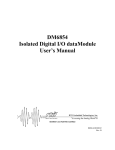
1
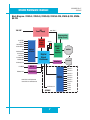
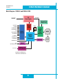
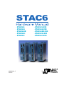
STAC6
• STAC6-S
• STAC6-Q • STAC6-QE
• STAC6-Si
• STAC6-C
920-0029 Rev. C
5/2/2012
• STAC6-S-220
• STAC6-Q-220
• STAC6-QE-220
• STAC6-Si-220
• STAC6-C-220
920-0029 Rev. C
5/2/2012
STAC6 Hardware manual
Contents
Safety Instructions............................................................................................................................4
Over-Current Protection....................................................................................................................5
Block Diagrams ................................................................................................................................6
Motion Control Options....................................................................................................................9
Getting Started................................................................................................................................10
Connecting to the PC using RS-232...............................................................................................11
Connecting to the PC using RS-485...............................................................................................12
Connecting to the CANopen Network..............................................................................................15
Connecting AC Power.....................................................................................................................17
Connecting the Motor.....................................................................................................................18
Connecting Other Motors................................................................................................................20
Connecting an Encoder ..................................................................................................................22
Wiring Inputs and Outputs..............................................................................................................24
Connecting Digital Inputs on the IN/OUT1 connector.....................................................................25
Connecting Digital Outputs on the IN/OUT1 connector...................................................................33
Connecting Analog Inputs on the IN/OUT1 connector.....................................................................35
Connecting Inputs and Outputs to IN/OUT2....................................................................................37
Connecting Digital Inputs on the IN/OUT2 connector.....................................................................37
Connecting Digital Outputs on the IN/OUT2 connector...................................................................42
Connecting Analog Inputs on the IN/OUT2 connector.....................................................................44
Recommended Motors....................................................................................................................45
Motor Dimensions..........................................................................................................................46
Torque-Speed Curves.....................................................................................................................49
Mounting the Drive.........................................................................................................................52
Mechanical Outline.........................................................................................................................53
Technical Specifications..................................................................................................................54
Mating Connectors and Accessories...............................................................................................56
Alarm Codes...................................................................................................................................57
2
920-0029 Rev. C
5/2/2012
STAC6 Hardware manual
(This page intentionally left blank)
3
920-0029 Rev. C
5/2/2012
STAC6 Hardware manual
Safety Instructions
Only qualified personnel are permitted to transport, assemble, commission, and maintain
this equipment. Properly qualified personnel are persons who are familiar with the transport, assembly, installation, commissioning and operation of motors, and who have the
appropriate qualifications for their jobs. The qualified personnel must know and observe the
following standards and regulations:
IEC 364 resp. CENELEC HD 384 or DIN VDE 0100
IEC report 664 or DIN VDE 0110
National regulations for safety and accident prevention or VBG 4
To minimize the risk of potential safety problems, you should follow all applicable local and national codes
that regulate the installation and operation of your equipment. These codes vary from area to area and it is
your responsibility to determine which codes should be followed, and to verify that the equipment, installation, and operation are in compliance with the latest revision of these codes.
Equipment damage or serious injury to personnel can result from the failure to follow all applicable codes
and standards. We do not guarantee the products described in this publication are suitable for your particular application, nor do we assume any responsibility for your product design, installation, or operation.
• Read all available documentation before assembly and commissioning. Incorrect handling of products
in this manual can result in injury and damage to persons and machinery. Strictly adhere to the technical
information on the installation requirements.
• It is vital to ensure that all system components are connected to earth ground. Electrical safety is impossible without a low-resistance earth connection.
• The STAC6 contains electrostatically sensitive components that can be damaged by incorrect handling.
Discharge yourself before touching the product. Avoid contact with high insulating materials (artificial
fabrics, plastic film, etc.). Place the product on a conductive surface.
• During operation keep all covers and cabinet doors shut. Otherwise, there are deadly hazards that could
possibility cause severe damage to health or the product.
• In operation, depending on the degree of enclosure protection, the product can have bare components that
are live or have hot surfaces. Control and power cables can carry a high voltage even when the motor is not
rotating.
4
920-0029 Rev. C
5/2/2012
STAC6 Hardware manual
• Never pull out or plug in the product while the system is live. There is a danger of electric arcing and
danger to persons and contacts.
• After powering down the product, wait at least ten minutes before touching live sections of the equipment
or undoing connections (e.g., contacts, screwed connections). Capacitors can store dangerous voltages for
long periods of time after power has been switched off. To be safe, measure the contact points with a meter
before touching.
Be alert to the potential for personal injury. Follow the recommended precautions and safe operating
practices. Safety notices in this manual provide important information. Read and be familiar with these
instructions before attempting installation, operation, or maintenance. The purpose of this section is to alert
users to possible safety hazards associated with this equipment and the precautions that need to be taken to
reduce the risk of personal injury and damage to the equipment.
Failure to observe these precautions could result in serious bodily injury, damage to the equipment ,or
operational difficulty.
Over-Current Protection
The STAC6 has hardware over-current detection circuits that protect the drive against “phase to ground”
and “phase to phase” motor shorts. These circuits directly disable the amplifier in a rapid fashion to prevent
damage to the driver circuitry.
Typically, the over-current circuitry will react to an over-current condition in 3 to 5 micro-seconds. For a
short occurring in a motor, the motor leads provide enough resistance and inductance to keep the peak
current from exceeding the peak rating of the power transistors during this time period. The recommended
motors for the STAC6 all include 10 foot cables.
In essence the motor/cable system is a part of the over-current circuitry. If the drive is
directly shorted with a very short wire, this condition may cause current conditions that
exceed the peak current rating of our power transistors and therefore could weaken or
cause failure in the drive power devices.
Repetitive short circuits also risk damage to the drive. If a short circuit fault occurs,
please power off the drive and investigate carefully before restoring power.
5
920-0029 Rev. C
5/2/2012
STAC6 Hardware manual
Block Diagrams
Block Diagram - STAC6-Si, STAC6-Si-220
DC
Power Supply
120 VAC*
160 VDC**
Regeneration
Clamp Circuit
X1/STEP
X2/DIR
X3/ENABLE
X4/ALMRST
X5
X6/CCWLIM
X7/CWLIM
Y1/FAULT
Y2/MOTION
Y3/BRAKE
Internal
Logic
Supply
Status
MOSFET
PWM
Power
Amplifier
Optical
Isolation
Digital
Signal
Processor
Interface
ANALOG IN
PC/MMI
RS485/422
RS232
RS485/422
Si™
Programmable
Controller
*220 VAC for STAC6-220
**320 VDC for STAC6-220
eeprom
ANALOG IN
6
Optical
Isolation
motor
encoder
INPUT1
INPUT2
INPUT3
INPUT4
INPUT5
INPUT6
INPUT7
INPUT8
OUT1
OUT2
OUT3
OUT4
920-0029 Rev. C
5/2/2012
STAC6 Hardware manual
Block Diagram - STAC6-S, STAC6-Q, STAC6-QE, STAC6-S-220, STAC6-Q-220, STAC6QE-220
DC
Power Supply
120 VAC*
160 VDC**
Regeneration
Clamp Circuit
X1/STEP
X2/DIR
X3/ENABLE
X4/ALMRST
X5
X6/CCWLIM
X7/CWLIM
Y1/FAULT
Y2/MOTION
Y3/BRAKE
Internal
Logic
Supply
Status
MOSFET
PWM
Power
Amplifier
Optical
Isolation
Digital
Signal
Processor
Interface
ANALOG IN
PC/MMI
RS485/422
RS232
RS485/422
Optical
Isolation
*220 VAC for STAC6-220
**320 VDC for STAC6-220
ANALOG IN
-QE ONLY
7
motor
encoder
INPUT1
INPUT2
INPUT3
INPUT4
INPUT5
INPUT6
INPUT7
INPUT8
OUT1
OUT2
OUT3
OUT4
920-0029 Rev. C
5/2/2012
STAC6 Hardware manual
Block Diagram - STAC6-C and STAC6-C-220
DC
Power Supply
120 VAC*
160 VDC**
Regeneration
Clamp Circuit
X1/STEP
X2/DIR
X3/ENABLE
X4/ALMRST
X5
X6/CCWLIM
X7/CWLIM
Y1/FAULT
Y2/MOTION
Y3/BRAKE
Internal
Logic
Supply
Optical
Isolation
Digital
Signal
Processor
ANALOG IN
PC
(for Setup Only)
CAN2.0b
RS232
CANopen
*220 VAC for STAC6-220
**320 VDC for STAC6-220
8
Status
MOSFET
PWM
Power
Amplifier
Interface
motor
encoder
920-0029 Rev. C
5/2/2012
STAC6 Hardware manual
Motion Control Options
STAC6-S Control Options
Basic drive: Analog, digital and host command input.
• Pulse & Direction, A/B Quadrature, CW/CCW Pulse.
• Velocity (Oscillator) Mode.
• Host command execution of SCL commands for control from a host PC or PLC using RS-232 or RS485 serial communication.
• Compatible with SiNet Hub 8 and SiNet Hub 444 for multi-axis Si programming.
STAC6-Q, STAC6-QE Control Options
Programmable drive: Built-in Q controller.
• Comprehensive single-axis programming language.
• Powerful feature set.
• Complex motion and machine control.
• Math functions.
• Register manipulation.
• Multi-tasking.
• Host interrogation/interface while executing internal programs.
• STAC6-QE comes with expanded I/O.
STAC6-Si Control Options
Programmable Drive: Built-in Si indexer.
• Easy-to-use Si Programmer™ software.
• Graphical point-and-click format combines motion, I/O, and operator interface.
• Stand-alone operation.
• Integrated Configurator for motor setup, encoder setup, and alarm history.
• Easily integrates with other devices such as sensors, PLCs, etc.
• Software and programming cable included.
STAC6-C Control Options
CANopen Node.
• Compliant to CANopen standards DS301
• Supports the following DSP402 operating modes:
• Profile Position Mode
• Profile Velocity Mode
• Homing Mode
• Additionally, supports stand-alone Q Programming with CANopen execution
9
920-0029 Rev. C
5/2/2012
STAC6 Hardware manual
Getting Started
This manual describes the use of STAC6 series of step motor drives. What you need to know and what you
must have depends on the drive model. For all models, you’ll need the following:
•
•
•
•
•
120VAC or 220VAC single phase power.
A compatible step motor (see recommended motors section)
A small flat blade screwdriver for tightening the connectors (included).
A personal computer running Microsoft Windows 98, 2000, NT, Me, XP or Vista or 7.
The Applied Motion CD (included)
If you’ve never used a STAC6 drive before you’ll need to get familiar with the drive and the set up software
before you try to deploy the system in your application. We strongly recommend the following:
1. For -S drives, install the STAC Configurator™ software application from the CD.
For -Q and QE drives, install the STAC Configurator™ and Q Programmer™ software applications from the CD.
For -Si drives, install and use the Si Programmer™ software for configuration and programming.
For -C drives, install the STAC Configurator™ and the CANopen Example Program software
applications from the CD. Q Programmer™ software may also be installed, if needed.
2. Launch the software by clicking Start...Programs...Applied Motion...
3. Connect the drive to your PC with the programming cable.
4. Connect the drive to the motor.
5. Connect the drive to the AC power.
6. Apply power to the drive.
10
STAC6 Hardware manual
920-0029 Rev. C
5/2/2012
Connecting to the PC using RS-232
• Locate your computer within 8 feet of the drive.
• Your drive was shipped with a communication cable. Plug the large end into the serial port of your PC
and the small end into the PC/MMI jack on your drive. Secure the cable to the PC with the screws on the
sides.
CAUTION
1. Never connect a drive to a telephone circuit. It uses the same connectors and cords as
telephones and modems, but the voltages are not compatible.
2. Drive ground and PC ground should be at the same potential. Different ground potentials
for the drive and PC can result in excessive current through the ground pin of the RS-232
port, resulting in failure of the port.
If your PC does not have a serial port, you should purchase a USB-serial converter to convert one of your
PC’s USB ports into an RS-232 (COM) port.
For 32-bit Windows operating systems, we have had good results with the Port Authority “USB Serial DB9”
Adapter from CablesToGo.com and with the SW1301 from SewellDirect.com. Some laptops also have a
PCMCIA slot, in which case the SSP-100 from Sewell Direct is a good choice.
For 64-bit Windows operating systems, namely Windows Vista 64 and Windows 7 64, the Prolific-based
adapters listed above do not work. For these PCs we suggest the USB-COMi-M or USB-CBL from Byterunner.com. These adapters also work the 32-bit operating systems.
For USB choices, refer to page 52.
ground (to PC ground)
TX (to PC RX)
RX (to PC TX)
No connection
Pin Assignments of the PC/MMI Port (RJ11 connector)
11
920-0029 Rev. C
5/2/2012
STAC6 Hardware manual
Connecting to the PC using RS-485
Pin diagram is shown to the right. Wiring diagrams can be found on this and the next
page. We recommend the use of Category 5 cable. It is widely used for computer networks, it is inexpensive, easy to get and certified for quality and data integrity.
RS-485/422
RS-485 allows you to connect more than one drive to a single host PC, PLC, HMI or other computer. It
also allows the communication cable to be long (more than 1000 feet). But the device to which you connect
must have an RS-422 or RS-485 port.
GND
TX–
TX+
RX–
RX+
The STAC6 drives can be used with either two wire or four wire RS-485 implementations. The connection
can be point to point (i.e. one drive and one host) or a multi-drop network (one host and up to 32 drives).
Four wire systems utilize separate transmit and receive wires. One pair of wires must connect the host
computer’s transmit signals to each drive’s RX+ and RX- terminals. Another pair connects the TX+ and TXdrive terminals to the host computer’s receive signals. A logic ground terminal is provided on each drive
and can be used to keep all drives at the same ground potential. This terminal connects internally to the DC
power supply return (V-), so if all the drives on the RS-485 network are powered from the same supply it is
not necessary to connect the logic grounds. You should still connect one drive’s GND terminal to
the host computer ground.
Four wire systems are better than two wire types because the host can send and receive data at the same
time, increasing system throughput. Furthermore, the host never needs to disable its transmitter, which
simplifies your software. We recommend that a 120 ohm terminating resistor be connected between RX+
and RX- at the farthest drive from the host.
to PC GND
to PC RXto PC RX+
to PC TX120
to PC TX+
+RX- +TX- GND
Drive #1
+RX- +TX- GND
Drive #2
+RX- +TX- GND
Drive #3
Two wire systems transmit and receive on the same pair of wires. The host must not only disable its
transmitter before it can receive data, it must do so quickly, before a drive begins to answer a query. The
12
920-0029 Rev. C
5/2/2012
STAC6 Hardware manual
STAC6 drives include a “transmit delay” parameter that can be adjusted to compensate for a host that is slow
to disable its transmitter. This adjustment can be made over the network using the TD command, or it can
be set using the STAC Configurator™ software. It is not necessary to set the transmit delay in a four wire
system. We recommend a 120 ohm terminating resistor be connected between the two transmit / receive
wires at the farthest drive from the host.
to PC GND
to PC TX- (A)
120
to PC TX+ (B)
+RX- +TX- GND
Drive #1
+RX- +TX- GND
Drive #2
+RX- +TX- GND
Drive #3
RS-232 to RS-485 2-wire Converter
Model 485-25E from Integrity Instruments (800-450-2001) works well for converting your PC’s RS-232 port
to RS-485. It comes with everything you need. Connect the adaptor’s “B” pin to the drive’s TX+
and RX+ terminals. Connect “A” to the drive’s TX- and RX- terminals.
Converting USB to RS-485
The USB-COMi-M from www.byterunner.com is an excellent choice for USB to RS-485 conversion. It can be
used with 2 wire or 4 wire systems.
For two wire RS-485, set SW1 to ON and SW2-4 to OFF. On the USB-COMi-M screw terminal connector:
Pin1 goes to RX- and TX-.
Connect pin 2 to RX+ and TX+.
Pin 6 is ground.
The DB-9 is not used.
For four wire RS-485, set SW1,3,4 to ON and SW2 to OFF. On the USB-COMi-M screw terminal connector: USB-COMi-MSTAC6 Drive
pin 1 RX-
pin 2
RX+
pin 3 TX+
pin 4 TXpin 6 GND
13
920-0029 Rev. C
5/2/2012
STAC6 Hardware manual
USB-COMi-M Switch Settings
4 Wire
RS-485
RS-232
ON
1 2 3 4
ON
1 2 3 4
2 Wire
RS-485
ON
1 2 3 4
Note: Prolific-based USB serial adapters do not work with Vista 64 or Windows 7 64 bit operating systems.
Suggested adapters are Byterunner USB-COMi-M or Byterunner USB-COM-CBL.
Assigning Addresses in Multi-axis Systems
Before wiring the entire system, you’ll need to connect each drive individually to the host computer so that
a unique address can be assigned to each drive. Use the programming cable and the STAC Configurator™
software that came with your drive for this purpose.
Connect the drive to your PC, then launch STAC Configurator™. Finally, apply power to your drive. If you
have already configured your drive, then you should click the Upload button so that the STAC Configurator™ settings match those of your drive. Click on the Motion button, then select the “SCL” operating mode.
If you have a Q drive, you may want to select “Q Programming”. Either way, you’ll see the RS-485 Address
panel appear. Just click on the address character of your choice. You can use the numerals 0..9 or the
special characters ! “ # $ % & ‘ ( ) * + , - . / : ; < = > ? @ . Just make sure that each drive on your network
has a unique address. If you are using a 2 wire network, you may need to set the Transmit Delay, too. 10
milliseconds works on the adapters we’ve tried. Once you’ve made your choices, click Download to save the
settings to your drive.
14
STAC6 Hardware manual
920-0029 Rev. C
5/2/2012
Connecting to the CANopen Network
GND
CAN_L
SHLD
CAN_H
CANopen Connector
The CANopen connector is a 4-pin spring lock type connector. The CANopen network should be connected
in a daisy-chain fashion, with a 120 ohm terminating resistor at each end of the network. Please see the
CANopen manual for more information.
Node ID Switch
Each node on a CANopen network must have a unique Node ID. On the STAC6, this is set using both the
Configurator software (above, left), as well as the sixteen position hardware switch on the front of the drive
(above, right). CANopen Node IDs are seven bits long, with a range of 1 - 127, or 0x01 - 0x7F in hexadecimal notation. The lower four bits, 0x0-0xF are set using the hardware switch, and the upper three bits, 0x0
- 0x7, are set using Configurator.
A Node ID of 0x39, for example, may be set by turning the switch on the drive to 9, and setting the Configurator software to a range of 0x30 - 0x3F.
15
920-0029 Rev. C
5/2/2012
STAC6 Hardware manual
Bit Rate Switch
The CANopen network bitrate is set by the rotary switch on the front of the drive. The bitrate must be the
same for all nodes on the CANopen network. The table below shows the various bitrates supported by
Applied Motion Products, and their corresponding switch settings. Please note, any changes to the bitrate
require either a powercycle or a CANopen reset command to take effect.
Octal Switch Setting
Resultant Bit Rate
0
1 Mbps
1
800 kbps
2
500 kbps
3
250 kbps
4
125 kbps
5
50 kbps
6
20 kbps
7
12.5 kbps
16
920-0029 Rev. C
5/2/2012
STAC6 Hardware manual
Connecting AC Power
Using the connector supplied connect to the AC supply per the diagram below. Use 16 AWG wire for Line
(L) and Neutral (N). Use 14 AWG for Earth Ground (G).
Care should always be taken when working with high voltages.
In regions where the single-phase supply is higher, an auto transformer can be used to drop the voltage to
the correct level.
Fusing
The STAC6 contains an internal 8A fast acting fuse. The STAC6-220 contains an internal 3.5A slo-blo (time
delay) fuse. If an external fuse is desired, we recommend a 6A fast acting fuse for the 120V STAC6 and a 5
amp fast acting fuse for the 220V version.
Line Filter
For applications requiring CE EMC compliance, a Corcom 6ET1 line filter is required in series with the AC
input.
green
eo
whit r blue
or
black brow
AC Power Plug
17
To Earth Ground
n
To Neutral
To Line (Hot)
920-0029 Rev. C
5/2/2012
STAC6 Hardware manual
Connecting the Motor
Never connect or disconnect the motor while the power is on.
Note: it is highly recommended that you use a motor with a shielded cable with the STAC6.
The recommended Applied Motion motors for the STAC6 include shielded cables. See the Recommended
Motors section for a list of part numbers. Note: If you need a rear shaft on the motor, for an encoder or
otherwise, make sure to add a “D” to the part number. Example: HT23-550D.
If your motor does not already have a connector attached or if you need to change the length of the cable,
please follow the illustrations below. Be sure to connect the cable shield for safety and to minimize electrical
interference.
Motors recommended for the STAC6-220 drives can also be used with 120V drives if they are wired in a
parallel configuration. See the diagram for parallel winding.
Series connection
• Use with all STAC6-220 drives and the following motors:
• HT23-552, HT23-553, HT23-554
• HT34-495, HT34-496, HT34-497
• Use with STAC6 (120) drives and the following motors:
• HT23-548, HT23-549, HT23-550
• HT34-488, HT34-489, HT34-490
YELLOW
BLUE
ORANGE
BROWN
WHITE
GREEN
RED
BLACK
SHIELD
A+
White
A+
Brown
A+
A
B+
B
SHLD
A–
Brown
8
lead
motor
Orange
SHLD
Orange
A–
Green
Red
Yellow
B+
Blue
White
Gree
Black
B–
Series Connected
8L
18
920-0029 Rev. C
5/2/2012
STAC6 Hardware manual
Parallel connection
• Do not use parallel connection with STAC6-220 drives.
• Use with STAC6 (120) drives and the following motors:
• HT23-552, HT23-553, HT23-554
• HT34-495, HT34-496, HT34-497
A+
A–
White
A+
YELLOW
Orange
BLUE
Brown
ORANGE
BROWN
Brown
Green
8
lead
motor
White
8
lead
motor
SHLD
WHITE
Black
Red
GREEN
Yellow
Blue
RED
B+
B–
BLACK
Series Connected
SHIELD
19
Orange
A–
A+
A
B+
B
SHLD
SHLD
Green
Red
Blue
B+
Yellow
Black
B–
8 Leads Parallel Connected
920-0029 Rev. C
5/2/2012
STAC6 Hardware manual
Connecting Other Motors
We can’t stress enough the wisdom in using one of the recommended motors. We’re not just trying to make
money here, we want your application to be successful and the odds of that are highest when you have a
high quality motor whose torque, rotor inertia and harmonic waveform content are precisely known. Furthermore, our motors include shielded cables to reduce electrical emissions and enhance safety and come with
pre wired mating connectors which further reduces the risk of error. If you do want to connect other motors ,
here is some information that will help
Four lead motors can only be connected one way. Please follow the sketch below.
A+
A–
Red
4
lead
motor
Blue
White
Yellow
B+
B–
4 Leads
Six lead motors can be connected in series or center tap. In series mode, motors produce more torque at
low speeds, but cannot run as fast as in the center tap configuration. In series operation, the motor should
be operated at 30% less than the rated current to prevent overheating. Winding diagrams for both connection methods are shown below. NC means not connected.
A–
NC
A+
Grn/Wht
Grn/Wht
A–
6
lead
motor
White
Green
A+
NC
Red
Black
B–
NC
Red/
Wht
Green
Red
B–
B+
6 Leads Series Connected
6
lead
motor
White
Black
B+
Red/
Wht
NC
6 Leads Center Tap Connected
20
920-0029 Rev. C
5/2/2012
STAC6 Hardware manual
Eight lead motors can also be connected in two ways: series and parallel. As with six lead motors, series
operation gives you less torque at high speeds, but may result in lower motor losses and less heating. In
series operation, the motor should be operated at 30% less than the unipolar rated current. The wiring
diagrams for eight lead motors are shown below.
A+
Orange
8
lead
motor
Org/Wht
Blk/Wht
A–
A+
Black
Red
B+
Red/
Wht
Yellow
Yel/
Wht B–
8 Leads Series Connected
Orange
Blk/Wht
Org/
Wht
A–
8
lead
motor
Black
Red
Yel/
B+ Wht
Yel
low
Red/Wht
8 Leads Parallel Connected
21
B–
920-0029 Rev. C
5/2/2012
STAC6 Hardware manual
Connecting an Encoder
The motors recommended for use with STAC6 drives are available with rear-shaft mounted encoders. Note:
remember to always order a double-shaft motor if you need an encoder option. The mating cables available
for these encoders come with an HD-15 connector on one end that connects directly to the Encoder connector on the STAC6, and a mating connector on the other end that connects directly to the encoder. Simply
connect the cable between the encoder and the drive and you’re done. For applications where you might use
your own encoder, you’ll need to connect to the STAC6 drive’s encoder connector using the pin assignments
below.
encoder B+ (3)
NC (9)
encoder B- (4)
NC (10)
encoder Z+ (5)
NC (15)
NC (14)
NC (13)
(8) GND
(2) encoder A(7) +5VDC 200mA
(1) encoder A+
(6) encoder Z-
(11) NC
(12) NC
If you are using an encoder with single ended outputs, shame on you. Differential connections are far less
sensitve to electrical interference and life is too short to waste time deciphering the bizarre problems that
can occur with a poor quality encoder. That said, single ended encoders should be connected to the A+ and
B+ terminals. Leave A- and B- unconnected. They are internally biased to the proper voltage for best results.
You’ll also need to select the “single ended” box in the Encoder button of STAC Configurator™ or the drive
will think you have a broken encoder wire. That’s another good reason to use a differential encoder, the
STAC6 can detect a broken wire or bad signal and alert you to the problem.
22
STAC6 Hardware manual
920-0029 Rev. C
5/2/2012
Encoder Feedback Options
The following encoder feedback options are configured and enabled using the STAC Configurator™ software.
Stall Detection continuously compares the actual motor position, as reported by the encoder, against the
theoretical motor position. If the motor lag reaches 7.2 mechanical degrees behind the target position, a
position fault occurs. This includes a motor at rest being driven out of position by an external force.
Stall Prevention can prevent many stalls before they occur. The STAC6 achieves this by using the encoder to
monitor the lead angle of the motor, a measure of torque utilization. If the motion profile begins to demand
more torque than the motor can produce, the velocity is automatically reduced before the motor stalls. To
engage stall prevention, simply check the Stall Prevention box in the STAC Configurator™ software and
enter the maximum torque utilization you want to allow.
In the event that the motor cannot move at all, such as hitting a hard stop, you may want to fault the drive
after a given amount of time by checking the Hard Stop box and entering a time limit.
23
920-0029 Rev. C
5/2/2012
STAC6 Hardware manual
Wiring Inputs and Outputs
The STAC6 drives come with a number of inputs and outputs for interfacing to external control hardware:
•
High speed digital inputs for step & direction commands or encoder following, 5V logic. These inputs, X1/STEP and X2/DIR, are available on all models. They can also be used to connect sensors and other types of devices. Connections to these inputs can be sourcing, sinking or differential.
•
Lower speed digital inputs for other signals, 12 - 24 volt logic, accepting sourcing, sinking or differential signals. All STAC6 models have 5 of these inputs on the IN/OUT1 connector. STAC6-QE and Si models only have a total of 13 of these inputs, 5 on the IN/OUT 1 connector and 8 on the IN/OUT 2 connector.
•
Analog inputs for analog speed and positioning modes, included on all drives. Can be configured for 0-10V, 0-5V, ±10V or ±5V, with or without offset. The STAC6-QE and Si models have an extra analog input rated at 0-5VDC - for use in SCL and Q applications only.
•
Digital Outputs rated at 30V, 100mA. There are three outputs on IN/OUT1, which is present on all models. STAC6-QE and Si models only have an additional 4 digital outputs on the IN/OUT2 connector.
Connector Pin Diagrams
IN/OUT 1
Analog IN+
Analog INX7 / CW Limit
X6 / CCW Limit
X5
X4 / Alarm Reset
X3 / Enable
X COMMON
X2 / DIRX2 / DIR+
X1 / STEP X1 / STEP +
GND
�
�
�
�
�
�
�
�
�
��
��
��
��
��
��
��
��
��
��
��
��
��
��
��
��
IN/OUT 2
Front View
Y1 / BRAKE
Y2 / MOTION
Y3 / FAULT
Y COMMON
+5V OUT
GND
GND
GND
+5V OUT
+12V OUT
IN 8IN 8+
IN 7IN 7+
IN 6
COM
IN 5
IN 4
COM
IN 3
IN 2
COM
IN 1
13
12
11
10
9
8
7
6
5
4
3
2
1
25
24
23
22
21
20
19
18
17
16
15
14
Out 4Out 4+
Out 3Out 3+
Out 2Out 2+
Out 1Out 1+
Ain Com
N/C
Ain 1
+5V
IN/OUT2 connector, this connector
is present on Si and QE models
IN/OUT1 connector, this connector
is present on all models
24
920-0029 Rev. C
5/2/2012
STAC6 Hardware manual
Connecting Digital Inputs on the IN/OUT1 connector
All STAC6 drives include two high speed inputs called STEP and
DIR. They accept 5 volt single-ended or differential signals, up to
2 MHz. Normally these inputs connect to an external controller
that provides step & direction command signals. You can also
connect a master encoder to the high speed inputs for following applications. Or you can use these inputs with Wait Input, If
Input, Feed to Sensor, Seek Home and other such commands.
Connection diagrams follow.
Indexer
with
Sourcing
Outputs
COM
DIR-
DIR
DIR+
STEP-
STEP
STEP+
IN/OUT1 Connector
High Speed Digital Inputs
12
X1/STEP+
11
X1/STEP10
X2/DIR+
9
X2/DIR-
STAC6
Stepper
Drive
IN/OUT 1
Connecting to indexer with Sourcing Outputs
Indexer
with
Sinking
Outputs
+5V OUT
DIR+
DIR
DIRSTEP+
STEP
STEP-
Connecting to Indexer with Sinking Outputs
25
STAC6
Stepper
Drive
IN/OUT 1
inside drive
920-0029 Rev. C
5/2/2012
Indexer
with
Differential
Outputs
STAC6 Hardware manual
DIR+
DIR+
DIR-
DIR-
STEP+
STEP+
STEP-
STEP-
STAC 6
IN/OUT 1
Master
Encoder
A+
STEP+
A-
STEP-
B+
DIR+
B-
DIR-
GND
GND
STAC 6
Connecting to Indexer with Differential Outputs
(Many high speed indexers have differential outputs)
Wiring for Encoder Following
(Encoder power can be supplied from the +5V OUT terminal on IN/OUT 1 if the encoder
requires no more than 100mA)
26
920-0029 Rev. C
5/2/2012
STAC6 Hardware manual
Using High Speed Inputs with 12-24 Volt Signals
Most PLCs don’t use 5 volt logic. You can connect signal levels as high as 24 volts to the STEP and DIR
inputs if you add external dropping resistors, as shown below.
For 12 volt logic, add 820 ohm, 1/4 watt resistors
For 24 volt logic, use 2200 ohm, 1/4 watt resistors
WARNING: The maximum voltage that can be applied directly to a high speed input terminal
is 24 volts. Never apply high voltage AC to an input terminal.
PLC
with
Sourcing
Outputs
+12-24V
OUT1
OUT2
R
R
GND
DIR+
STEP-
STAC 6
Drive
STEP+
DIR-
Connecting to PLC with Sourcing (PNP) Outputs (Most PLC’s use 24 volt logic)
PLC
with
Sinking
Outputs
+12-24V
DIR
STEP
DIR+
R
R
DIRSTEP+
STAC6
Drive
STEP-
Connecting to PLC with Sinking (NPN) Outputs (Most PLC’s use 24 volt logic)
27
920-0029 Rev. C
5/2/2012
STAC6 Hardware manual
+
DIR+
direction switch
+24VDC
Power
Supply
run/stop switch
(closed=run)
-
DIR-
2200
STEP+
2200
STAC6
Drive
STEP-
Using Mechanical Switches at 24 Volts.
Standard Digital Inputs
As we mentioned above, the high speed STEP and DIR inputs are configured for five volt logic. All other
digital inputs are designed for operation between 12 and 24 volts DC. This includes five inputs on the IN/
OUT 1 connector of all drives (X3-X7) and the eight digital inputs on the IN/OUT 2 connector of -Si and -QE
drives only (inputs IN1-IN8).
Single Ended Inputs
The STAC6 drives include single ended, optically isolated input circuits that can be used with sourcing or
sinking signals, 12 to 24 volts. This includes inputs X3-X7 on the IN/OUT 1 connector and inputs IN1 - IN6
on the IN/OUT 2 connector. This allows connection to PLCs, sensors, relays and mechanical switches.
Because the input circuits are isolated, they require a source of power. If you are connecting to a PLC, you
should be able to get power from the PLC power supply. If you are using relays or mechanical switches, you
will need a 12-24 V power supply. This also applies if you are connecting the inputs to the programmable
outputs of another Si product from Applied Motion.
inside IN/OUT1
2200
6
X4/ALRM RST
2200
5
X5
2200
3
X7/CW LMT
2200
4
X6/CCW LMT
2200
STAC-6
8
COM
7
X3/ENABLE
28
920-0029 Rev. C
5/2/2012
STAC6 Hardware manual
What is COM?
“Common” is an electronics term for an electrical connection to a common voltage. Sometimes “common”
means the same thing as “ground”, but not always. In the case of the STAC6, if you are using sourcing
(PNP) input signals, then you will want to connect COM to ground (power supply -). If you are using sinking
(NPN) signals, then COM must connect to power supply +.
Note: If current is flowing into or out of an input, the logic state of that input is low or closed. If no current is
flowing, or the input is not connected, the logic state is high or open.
Digital Input Connection Examples
12-24
VDC
Power
Supply
X COM
+
switch or relay
IN/OUT1
(closed=logic low)
-
X3..X7
Connecting an Input to a Switch or Relay
29
920-0029 Rev. C
5/2/2012
12-24
VDC
Power
Supply
STAC6 Hardware manual
+
-
+
NPN
Proximity
Sensor
–
XCOM
COM
output
STAC6
X3...X7
IN
IN/OUT1
Connecting an NPN Type Proximity Sensor to an input
(When prox sensor activates, input goes low).
12-24
VDC
Power
Supply
+
-
+
PNP
Proximity
Sensor
–
output
X3..X7
IN/OUT1
XCOM
COM
Connecting a PNP Type Proximity Sensor to an input
30
STAC6 Hardware manual
920-0029 Rev. C
5/2/2012
Connecting Limit switches to the STAC6 Drive
The X7/CW LIMIT and X6/CCW LIMIT inputs are used for connecting end of travel sensors. These inputs
are differential, which allows you to use signals that are sinking (NPN), sourcing (PNP) or differential (line
driver). By connecting switches or sensors that are triggered by the motion of the motor or load, you can
force the motor to operate within certain limits. This is useful if a program or operator error could cause
damage to your system by traveling too far.
The limit inputs are optically isolated. This allows you to choose a voltage for your limit circuits of 12 to 24
volts DC. This also allows you to have long wires on limit sensors that may be far from the drive with less
risk of introducing noise to the drive electronics. The schematic diagram of the limit switch input circuit is
shown below.
inside STAC6
8
X COM
X7/CW LMT
3
4
X6/CCW LMT
IN/OUT 1 Connector
2200
2200
Wiring a Mechanical Limit Switch
You can use normally open or normally closed limit switches. Either way, wire them as shown here.
+
12-24
VDC
SUPPLY
-
X COM
X7/CW LMT
STAC6
Stepper
X6/CCW LMT
31
920-0029 Rev. C
5/2/2012
STAC6 Hardware manual
Wiring a Limit Sensor
Some systems use active limit sensors that produce a voltage output rather than a switch or relay closure.
These devices must be wired differently than switches.
If your sensor has an open collector output or a sinking output, wire it like this:
X COM
+
DC
Power
Supply
–
+
Limit
Sensor
–
output
STAC6
Stepper
X6..X7
If the sensor output goes low at the limit, select the option “closed” (in the software). If the output is open,
or high voltage, choose “open”.
Other sensors have sourcing outputs. That means that current can flow out of the sensor output, but not into
it. In that case, wire the sensor this way:
+
DC
Power
Supply
–
+
Proximity
Sensor
–
output
X6..X7
STAC6
Stepper
X COM
32
STAC6 Hardware manual
920-0029 Rev. C
5/2/2012
Connecting Digital Outputs on the IN/OUT1 connector
IN/OUT 1
Analog IN+
Analog INX7 / CW Limit
X6 / CCW Limit
X5
X4 / Alarm Reset
X3 / Enable
X COMMON
X2 / DIRX2 / DIR+
X1 / STEP X1 / STEP +
GND
�
�
�
�
�
�
�
�
�
��
��
��
��
��
��
��
��
��
��
��
��
��
��
��
��
Front View
Y1 / BRAKE
Y2 / MOTION
Y3 / FAULT
Y COMMON
+5V OUT
GND
GND
GND
+5V OUT
+12V OUT
All STAC6 drives feature three digital outputs on the IN/OUT 1 connector:
Y1/Brake: controls an electric brake relay, automatically releasing and engaging as the drive requires
Y2/Motion: indicates that the drive has achieved a desired goal, such as a target position
Y3/Fault: closes when a drive fault occurs. The red and green LEDs will flash an error code.
14
Y1/BRAKE
17
Y COM
inside STAC-6
Y3/FAULT
16
15
Y2/MOTION
These outputs can be used to drive LEDs, relays and the inputs of other electronic devices like PLCs and
counters. These outputs can only sink current.
The COM terminal must be tied to power supply (-).
33
920-0029 Rev. C
5/2/2012
STAC6 Hardware manual
Diagrams of different connections follow.
Do not connect the outputs to more than 30VDC.
The current through each output terminal must not exceed 100 mA.
5-24 VDC
Power Supply
+
Y1..Y3
–
Load
STAC6
YCOM
relay
5-24 VDC
Power Supply
+
Y1..Y3
STAC6
1N4935 suppression diode
YCOM
34
–
STAC6 Hardware manual
920-0029 Rev. C
5/2/2012
Connecting Analog Inputs on the IN/OUT1 connector
IN/OUT 1
Analog IN+
Analog INX7 / CW Limit
X6 / CCW Limit
X5
X4 / Alarm Reset
X3 / Enable
X COMMON
X2 / DIRX2 / DIR+
X1 / STEP X1 / STEP +
GND
�
�
�
�
�
�
�
�
�
��
��
��
��
��
��
��
��
��
��
��
��
��
��
��
��
Front View
Y1 / BRAKE
Y2 / MOTION
Y3 / FAULT
Y COMMON
+5V OUT
GND
GND
GND
+5V OUT
+12V OUT
All STAC6 drives have two analog input pins that can be used separately as two, single-ended analog inputs
or together as one, differential analog input. Whether separate or together, the maximum range that can be
applied to these pins is +/- 10V. The analog input(s) can be used by the drive for a number of dedicated
purposes for controlling the motor or can be used for general purpose analog input signals.
+10V to -10V
Signal
signal return
1
AIN+
13
GND
STAC-6
The analog input can be used for:
• Analog Velocity Mode
• Analog Positioning Mode.
Both of these modes use the analog input for commanding the stepper drive.
Other uses include using an analog signal to stop a move when using any of the “Feed to Sensor” type
moves and waiting on an analog signal using the “Wait on Input”.
35
920-0029 Rev. C
5/2/2012
STAC6 Hardware manual
Basic Specifications:
• The analog input can accept ±10 Volts.
• The input has an impedance of 20K ohms.
• Because of the nature of the design, the input will exhibit a 1.4V offset when not driven by an analog
source.
• Low source impedance is important for minimizing analog errors, 100 ohms or lower is recommended.
WARNING - The analog input must be used with care. It is not optically isolated and may
operate improperly or could be damaged when system grounds are not compatible.
Connecting an Analog Input to a Potentiometer or Joystick
24
1k-10k
pot
+5V
��
1
���
13
2
AIN+
GND
AIN-
36
STAC6 Hardware manual
920-0029 Rev. C
5/2/2012
Connecting Inputs and Outputs to IN/OUT2
The IN/OUT2 connector is present as standard on the Si version of the drive. It is also standard on the QE
version.
Connecting Digital Inputs on the IN/OUT2 connector
IN/OUT 2
IN 8IN 8+
IN 7IN 7+
IN 6
COM
IN 5
IN 4
COM
IN 3
IN 2
COM
IN 1
13
12
11
10
9
8
7
6
5
4
3
2
1
25
24
23
22
21
20
19
18
17
16
15
14
Out 4Out 4+
Out 3Out 3+
Out 2Out 2+
Out 1Out 1+
Ain Com
N/C
Ain 1
+5V
Digital Inputs
Single Ended Inputs
The STAC6-Si and STAC6-QE include single ended, optically isolated input circuits that can be used with
sourcing or sinking signals, 12 to 24 volts. The IN/OUT 2 connector has 6 of these inputs (IN1 - IN6). These
inputs allow connection to PLCs, sensors, relays and mechanical switches. Because the input circuits are
isolated, they require a source of power. If you are connecting to a PLC, you should be able to get power
from the PLC power supply. If you are using relays or mechanical switches, you will need a 12-24 V power
supply. This also applies if you are connecting the inputs to the programmable outputs of another Si product
from Applied Motion.
What is COM?
“Common” is an electronics term for an electrical connection to a common voltage. Sometimes “common”
means the same thing as “ground”, but not always. In the case of the STAC6, if you are using sourcing
(PNP) input signals, then you will want to connect COM to ground (power supply -). If you are using sinking
(NPN) signals, then COM must connect to power supply +.
37
920-0029 Rev. C
5/2/2012
STAC6 Hardware manual
inside IN/OUT2
IN1
COM
IN2
IN3
COM
IN4
CWJOG
COM
CCWJOG
2200
2200
2200
2200
2200
2200
Connecting an Input to a Switch or Relay
12-24
VDC
Power
Supply
COM
+
STAC6
switch or relay
(closed=logic low)
-
IN
Use normally open momentary switch to trigger drive using Wait Input instruction.
Use single throw switch for parameter selection using If Input instruction.
Use normally open momentary switch for jogging.
38
920-0029 Rev. C
5/2/2012
STAC6 Hardware manual
+
COM
OUT+
IN
12-24
VDC
Power
Supply
IN/OUT2
Si354, 7080i etc
Connecting another Si Drive
OUT–
-
(When output closes, drive input goes low).
Connecting an NPN Type Proximity Sensor to an input
12-24
VDC
Power
Supply
COM
+
-
+
output
NPN
Proximity
Sensor
–
IN
IN/OUT2
(When prox sensor activates, drive input goes low).
Connecting a PNP Type Proximity Sensor to an input
12-24
VDC
Power
Supply
+
-
+
output
PNP
Proximity
Sensor
–
IN
IN/OUT2
COM
(When prox sensor activates, drive input goes low).
39
920-0029 Rev. C
5/2/2012
STAC6 Hardware manual
Differential Inputs
The IN/OUT2 connector also includes two differential, optically isolated input circuits that can be used with
sourcing or sinking signals, 12 to 24 volts. They are labeled IN7 and IN8. These inputs allow connection
to PLCs, sensors, realys and mechanical switches. Because the input circuits are isolated, they require a
source of power. If you are connecting to a PLC, you should be able to get power from the PLC power supply. If you are using relays or mechanical switches, you will need a 12-24 V power supply. This also applies
if you are connecting the inputs to the programmable outputs of another Si product from Applied Motion.
inside drive
IN7+
IN7IN8+
IN8-
+
5-24
VDC
SUPPLY
-
IN+
STAC6
IN-
Connecting a Mechanical Switch to a Differential Input
40
920-0029 Rev. C
5/2/2012
STAC6 Hardware manual
IN+
+
DC
Power
Supply
–
+
output
NPN
Proximity
Sensor
–
STAC6
IN-
Connecting an NPN Proximilty Sensor to a Differential Input
+
DC
Power
Supply
–
+
output
PNP
Proximity
Sensor
–
IN+
STAC6
IN-
Connecting a PNP Proximilty Sensor to a Differential Input
41
920-0029 Rev. C
5/2/2012
STAC6 Hardware manual
Connecting Digital Outputs on the IN/OUT2 connector
IN/OUT 2
IN 8IN 8+
IN 7IN 7+
IN 6
COM
IN 5
IN 4
COM
IN 3
IN 2
COM
IN 1
13
12
11
10
9
8
7
6
5
4
3
2
1
25
24
23
22
21
20
19
18
17
16
15
14
Out 4Out 4+
Out 3Out 3+
Out 2Out 2+
Out 1Out 1+
Ain Com
N/C
Ain 1
+5V
Digital Outputs
The expanded I/O board adds four additional programmable outputs. The outputs can be used to drive
LEDs, relays and the inputs of other electronic devices like PLCs and counters. On the IN/OUT 2 connector
outputs, both the “+” (collector) and “-” (emitter) terminals of each transistor are available on the connector
pins. This allows you to configure each output for current sourcing or sinking.
IN/OUT 2
OUT1+
OUT1OUT2+
OUT2OUT3+
OUT3OUT4+
OUT4-
Diagrams of each type of connection follow.
42
920-0029 Rev. C
5/2/2012
STAC6 Hardware manual
Do not connect the outputs to more than 30VDC. The current through each output terminal
must not exceed 100 mA.
12-24 VDC
Power Supply
STAC6-Si
STAC6-QE
+
–
OUT+
COM
OUT-
IN
PLC
Connecting output as a sourcing output.
5-24 VDC
Power Supply
+
STAC6-Si
STAC6-QE
–
Load
OUT+
OUT-
Connecting outputs as a sinking output.
relay
5-24 VDC
Power Supply
+
STAC6-Si
STAC6-QE
–
OUT+
1N4935 suppression diode
OUT-
Using output to control a relay.
43
920-0029 Rev. C
5/2/2012
STAC6 Hardware manual
Connecting Analog Inputs on the IN/OUT2 connector
IN/OUT 2
IN 8IN 8+
IN 7IN 7+
IN 6
COM
IN 5
IN 4
COM
IN 3
IN 2
COM
IN 1
13
12
11
10
9
8
7
6
5
4
3
2
1
25
24
23
22
21
20
19
18
17
16
15
14
Out 4Out 4+
Out 3Out 3+
Out 2Out 2+
Out 1Out 1+
Ain Com
N/C
Ain 1
+5V
Connecting to the Aux Analog Input (Ain 1)
The auxiliary analog input on the STAC6 IN/OUT 2 connector can be read back to the “Host” using the “IA”
immediate type and “RA” buffered type Host commands.
See “Host Command Reference” for more information.
+5 volt DC is provided for powering potentiometers. A 1000 to 10000 ohm potentiometer is recommended.
A 0 to 5 volt analog signal may also be used. Usually this signal comes from a PLC, a PC with data acquisition card or a motion controller. Connections are shown below.
The +5V terminal is an output. Do not connect it to a power supply.
0 - 5V
speed signal
AIN
signal return
GND
Connecting an Analog Input to an Active Signal
44
920-0029 Rev. C
5/2/2012
STAC6 Hardware manual
Recommended Motors
Applied Motion offers 12 recommended motors for use with the STAC6 drives. All 12 of these motors
are recommended for use with the STAC6 (120) drives, but the connection to the drive should be series
or parallel depending on the motor. See the Connecting the Motor section for details. 6 of these motors
are recommended for the STAC6-220 drives. These motors have their characteristics stored in the STAC
Configurator™ software making it easy to setup and configure them. For reference below is additional
information about these motors.
All recommended STAC6 motors have 10ft shielded cables which act as part of the over-current protection
circuit. See Over-Current Protection section earlier in this manual for details.
Recommended Motors - NEMA 23
STAC6 (120)
Motor Part No.
STAC6-220
Rotor Inertia
oz-in-sec^2
Motor Length
inch (mm)
Connection
HT23-548
series
1.50
do not use
84.4
1.70E-03
1.71 (43.5)
HT23-549
series
1.50
do not use
167
4.25E-03
2.17 (55)
HT23-550
series
1.80
do not use
255
6.80E-03
3.05 (77.5)
HT23-552
parallel
1.50
series
0.75
84.4
1.70E-03
1.71 (43.5)
HT23-553
parallel
1.50
series
0.75
167
4.25E-03
2.17 (55)
HT23-554
parallel
1.80
series
0.90
255
6.80E-03
3.05 (77.5)
Connection
Drive Current Setting
amps/phase
Holding Torque
oz-in
Drive Current Setting
amps/phase
Recommended Motors - NEMA 34
STAC6 (120)
STAC6-220
Motor Part No.
Rotor Inertia
oz-in-sec^2
Motor
Length
inch (mm)
Front Shaft
Diameter
inch (mm)
555
2.27E-02
3.11 (79)
0.5 (12.7)
1110
4.53E-02
4.63 (117.5)
0.5 (12.7)
1694
6.80E-02
6.14 (156)
0.625
(15.875)
Connection
Drive Current Setting
amps/phase
HT34-488
series
5.10
HT34-489
series
5.10
HT34-490
series
5.80
HT34-495
parallel
5.10
series
2.55
555
2.27E-02
3.11 (79)
0.5 (12.7)
HT34-496
parallel
5.10
series
2.55
1110
4.53E-02
4.63 (117.5)
0.5 (12.7)
HT34-497
parallel
5.80
series
3.20
1694
6.80E-02
6.14 (156)
0.625
(15.875)
Connection
Drive Current Setting
amps/phase
Holding Torque
oz-in
do not use
do not use
do not use
Note: The “Drive Current Setting” shown here differs from the rated current of each motor because the rated
current is RMS and the drive current setting is peak sine. If you are using a motor not listed here, for best
results set the drive current at the motor’s rated current x 1.2.
45
920-0029 Rev. C
5/2/2012
STAC6 Hardware manual
Motor Dimensions
HT23 Motors
220V MOTORS DO NOT HAVE A CONNECTOR AND BOOT
"L"
.197
.063
120” MIN
Ø.250
.591
.59
Ø1.50
4 x Ø.205
Ø.250
2 x 1.856
1.11
2 x 2.22
.228
FLAT
.630
.787
2 x #4-40 UNC ON Ø1.82 BCD
2X 2-56 UNC TAP THRU 180°
APART ON A Ø19.05 B.C.
46
.928
920-0029 Rev. C
5/2/2012
STAC6 Hardware manual
Motor Dimensions
HT34 Motors
220V MOTORS DO NOT HAVE A CONNECTOR AND BOOT
1.12
“L”
.330
.062
120" MIN
4x
Ø.218THRU
Ø 2.875
See shaft
detail
2X 2-56 UNC 5(.2)
DEEP ON A
Ø1.28(32.5) B.C.
Ø .3750
1.25
2X #4-40 UNC TAP 5(.2) DEEP 180°
APART ON A Ø46.02(1.812) B.C.
47
2X 2.74
3.38
920-0029 Rev. C
5/2/2012
STAC6 Hardware manual
HT34 Motors (cont)
Shaft Detail 1 - motor with 0.5” shaft
1.25±.02
Ø.500+.0000
.125
.555
.875±.010
Shaft Detail 2 - motors with 0.625” shaft
1.25±.02
0
Ø.6250+.0000
.1875
.875±.010
.705
48
920-0029 Rev. C
5/2/2012
STAC6 Hardware manual
Torque-Speed Curves
HT23‐552/553/554, STAC6 (120)
Connection: parallel
Step resolution: 1/100 (20,000 s/r)
HT23‐552
HT23‐553
HT23‐554
250
(oz‐in)
200
150
100
50
0
0
10
20
30
40
50
(rps)
HT23‐552/553/554, STAC6‐220
Connection: series
Step resolution: 1/100 (20,000 s/r)
HT23‐552
HT23‐553
HT23‐554
250
(oz‐in)
200
150
100
50
0
0
10
20
30
40
(rps)
49
50
920-0029 Rev. C
5/2/2012
STAC6 Hardware manual
Torque-Speed Curves
HT34‐495/496/497, STAC6 (120)
Connection: parallel
Step resolution: 1/100 (20,000 s/r)
HT34‐495
HT34‐496
HT34‐497
1600
1400
1200
(oz‐in)
1000
800
600
400
200
0
0
10
20
30
40
50
(rps)
HT34‐495/496/497, STAC6‐220
Connection: series
Step resolution: 1/100 (20,000 s/r)
HT34‐495
HT34‐496
HT34‐497
1600
1400
1200
(oz‐in)
1000
800
600
400
200
0
0
10
20
30
(rps)
50
40
50
920-0029 Rev. C
5/2/2012
STAC6 Hardware manual
Torque-Speed Curves
HT23‐548/549/550, STAC6 (120)
Connection: series
Step resolution: 1/100 (20,000 s/r)
HT23‐548
HT23‐549
HT23‐550
250
(oz‐in)
200
150
100
50
0
0
10
20
30
40
50
(rps)
HT34‐488/489/490, STAC6 (120)
Connection: series
Step resolution: 1/100 (20,000 s/r)
HT34‐488
HT34‐489
HT34‐490
1600
1400
1200
(oz‐in)
1000
800
600
400
200
0
0
10
20
30
40
(rps)
51
50
920-0029 Rev. C
5/2/2012
STAC6 Hardware manual
Mounting the Drive
You can mount your drive on the wide or the narrow side of the chassis using #6 screws. If possible, the
drive should be securely fastened to a smooth, flat metal surface that will help conduct heat away from the
chassis. If this is not possible, then forced airflow from a fan may be required to prevent the drive from
overheating.
• Never use your drive in a space where there is no air flow or where other devices cause
the surrounding air to be more than 55°C.
• Never put the drive where it can get wet or where metal or other electrically conductive
particles can get on the circuitry.
• Always provide air flow around the drive. When mounting multiple STAC6 drives near
each other, maintain at least one half inch of space between drives.
52
920-0029 Rev. C
5/2/2012
STAC6 Hardware manual
Mechanical Outline
.120
.150
.300
.300
.76 TYP
.50 TYP
6.345 6.925 7.345
.300
.68
4.66
.20
.180
2.31
1.76
53
920-0029 Rev. C
5/2/2012
STAC6 Hardware manual
Technical Specifications
POWER AMPLIFIER SECTION
AMPLIFIER TYPE
MOSFET , Dual H-Bridge, 4 Quadrant
CURRENT CONTROL
4 state PWM at 20 Khz
OUTPUT CURRENT
STAC6
STAC6-220
0.5— 6.0 amps in 0.01 amp increments (6A peak of sine)
0.5— 3.2 amps in 0.01 amp increments (3.2A peak of sine)
POWER SUPPLY
STAC6
STAC6-220
Line Operated Nominal 120 VAC, 50/60 Hz
Line Operated Nominal 220 VAC, 50/60 Hz
AC INPUT VOLTAGE
STAC6
STAC6-220
94—135VAC, 50/60Hz
94—265VAC, 50/60Hz
PROTECTION
Over-voltage, under-voltage, over-temp, external output shorts (phase to-phase, phase-toground), internal amplifier shorts
IDLE CURRENT REDUCTION
Reduction to any integer percent of full-current after delay selectable in milliseconds.
MOTOR REGENERATION
Built in regeneration circuit - 25watts max.
CONTROLLER SECTION
NON-VOLATILE STORAGE
STEP AND DIRECTION INPUTS
RESOLUTION
ANTI RESONANCE
(Electronic Damping)
TORQUE RIPPLE SMOOTHING
SELF TEST AND AUTO SETUP
MICROSTEP EMULATION
COMMAND SIGNAL SMOOTHING
ENCODER OPTION
INTERFACE
AMBIENT TEMPERATURE
HUMIDITY
Configurations are saved in FLASH memory on board the DSP.
Optically Isolated: 5 Volt. Minimum pulse width = 200 ns. Maximum pulse frequency
= 2 MHz
Software selectable from 200 to 51200 steps/rev in increments of 2 steps/rev
Raises the system damping ratio to eliminate midrange instability and allow stable
operation throughout the speed range and improves settling time.
Allows for fine adjustment of phase current waveform harmonic content to reduce lowspeed torque ripple in the range 0.25 — 1.5 rps.
Checks internal & external power supply voltages, diagnoses open motor phases.
Measures motor parameters and configures motor current control and anti-resonance
gain settings.
Performs low resolution stepping by synthesizing fine microsteps from coarse steps.
Software configurable filtering reduces jerk and excitation of extraneous system
resonances (step & direction mode only)
Employs encoder (hi or low resolution) to provide failsafe stall detect and perform stall prevention and position maintenance. Differential line receivers suitable for 500 kHz
or greater. Minimum encoder resolution is 1000 lines.
RS-232 and RS-485 , CANopen standard on STAC6-C models.
0 to 55 oC (32- 158 oF)
90% non-condensing
54
STAC6 Hardware manual
920-0029 Rev. C
5/2/2012
INPUTS AND OUTPUTS
IN / OUT 1 connector - All Drives
7 Inputs
X1, X2
X3
Optically Isolated, Differential, 5 Volt. Minimum pulse width = 250ns. Maximum pulse,
frequency = 2 MHz
Function: Step & Direction, Encoder Following, Sensor, Home or Branch Select
Optically isolated, 12 - 24V, sourcing or sinking. Function: Motor Enable, Sensor, Home
or Branch Select. X3 - X7 have shared common.
X4
Optically isolated, 12 - 24V, sourcing or sinking. Function: Alarm Reset, Sensor, Home or
Branch Select. X3 - X7 have shared common.
X5
Optically isolated, 12 - 24V. Function. Function; general Purpose Input. X3 - X7 have
shared common.
X6,X7
Optically isolated, 12 - 24V. Function: CW & CCW Limits, Sensor, Home or Branch Select.
X3 - X7 have shared common.
3 Outputs
Y1
Optical darlington, 30V, 100mA max, NPN/sinking, shared common with Y2 & Y3.
Function: Brake or general purpose programmable
Y2
Optical darlington, 30V, 100mA max, NPN/sinking, shared common with Y1 & Y3.
Function: Motion, tach or general purpose programmable
Y3
Optical darlington, 30V, 100mA max, NPN/sinking, shared common with Y1 & Y2.
Function: Fault or general purpose programmable
Analog Inputs
Software selectable:
0-5V, ±5V, 0-10V, ±10V,
RESOLUTION
12 bits (with ±10V signal range)
11 bits (with 0-10V or ±5V signal range)
10 bits (with 0-5V signal range)
IN / OUT 2 connector - QE and Si
8 Digital Inputs
IN1-IN6
Optically isolated, 12 - 24V. Function. Function; general Purpose Input. Shared common.
IN7,IN8
Optically isolated, differential. 12 - 24V. Function; general Purpose Input.
4 Digital Outputs
OUT 1-4
Optical darlington, 30V, 100mA max, sinking or sourcing. Function: general purpose
programmable
1 Analog Input
0-5VDC analog input - for use with Q or SCL applications only
55
920-0029 Rev. C
5/2/2012
STAC6 Hardware manual
Mating Connectors and Accessories
Mating Connector
(Type)
Included with Drive
Additional/Recommended
Motor (5-position, screw terminal)
-
Phoenix Contact 1757048,
1792786
AC Power (3-position, screw
terminal)
Phoenix Contact 1767012
Phoenix Contact 1832426,
1832536
RS485 Logic (3-position, screw
terminal)
Phoenix Contact 1827622
-
IN/OUT1 (DB-25 male)
Norcomp 171-025-103L001 connector,
Mouser 40-9725HS shell kit
-
IN/OUT2 (DB-25 female)
Norcomp 171-025-203L011 connector,
Mouser 40-9725HS shell kit
-
-
Norcomp 180-015-102-001 connector, AMP 5-748678-1 shell kit
Encoder (HD-15 male)
Accessories
Breakout Box for DB-25 Connectors
BOB-1, includes cable, connects to IN/OUT 1
BOB-2, includes cable, connects to IN/OUT 2
Screw Terminal Connectors that mate directly to the DB-25 connector on the front panel of the drive:
Phoenix Contact P/N 2761622
This connector is not available from Applied Motion. You must purchase it from a
Phoenix distributor.
Mating Cable for IN/OUT2 connector with “flying leads”
Black Box P/N: BC00702
This cable is not available from Applied Motion. You must purchase it from Black Box.
Useful for custom wired applications. This shielded cable has a DB-25 connector on each
end. You can cut off the female end to create a 6 foot “DB-25 to flying lead cable”.
It’ll be easier to wire if you get the cable color chart from Black Box’s web site.
Recommended CANopen USB Adapter (-C drives only)
Kvaser LeafLight HS This adapter is not available from Applied Motion Products
Note: Prolific-based USB serial adapters do not work with Vista 64 or Windows 7 64 bit operating systems.
Suggested adapters are Byterunner USB-COMi-M or Byterunner USB-COM-CBL or USB-COMi. (USB)
Serial Adapters:
For 32-bit Windows operating systems:
Port Authority “USB Serial DB9” Adapter from CablesToGo.com (USB).
SW1301 from SewellDirect.com (USB).
SSP-100 from Sewell Direct (PCMCIA)
For 64-bit and 32-bit Windows operating systems:
Byterunner USB-COM-CBL or USB-COMi. (USB)
56
STAC6 Hardware manual
920-0029 Rev. C
5/2/2012
Alarm Codes
In the event of an error, the green LED on the main board will flash one or two times, followed by a series of
red flashes. The pattern repeats until the alarm is cleared.
Code
solid green
flashing green
1 red, 1 green
1 red, 2 green
1 red, 3 green
2 red, 1 green
2 red, 2 green
2 red, 3 green
3 red, 1 green
3 red, 2 green
3 red, 3 green
4 red, 1 green
4 red, 2 green
4 red, 3 green
5 red, 1 green
5 red, 2 green
6 red, 1 green
6 red, 2 green
7 red, 1 green
7 red, 2 green
8 red, 1 green
Error
no alarm, motor disabled
no alarm, motor enabled
motor stall (optional encoder only)
move attempted while drive disabled
subroutine stack overflow (Si only)
ccw limit
cw limit
subroutine stack underflow (Si only)
drive overheating
internal voltage out of range
blank Q segment
power supply overvoltage
power supply undervoltage
bad instruction in Si program
over current / short circuit
motor resistance out of range
open motor winding
bad encoder signal (optional encoder only)
serial communication error
flash memory error
internal voltage out of range
Applied Motion Products, Inc.
404 Westridge Drive Watsonville, CA 95076
Tel (831) 761-6555
(800) 525-1609
Fax (831) 761-6544
www.appliedmotionproducts.com
57