1
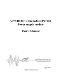
DM5852HR/DM6852HR
Isolated Digital I/O-module
User’ Manual
AS9100 and ISO 9001 Certified
BDM-610010026
Rev. C
RTD Embedded Technologies, INC.
103 Innovation Blvd.
State College, PA 16803-0906
Phone: +1-814-234-8087
FAX: +1-814-234-5218
E-mail
[email protected]
[email protected]
Web site
http://www.rtd.com
DM5852HR/DM6852HR Isolated Digital I/O Module User’s Manual
i
Revision History
Rev A
Initial Release
Rev B
Fix up Typos.
Add in diagram of isolated input section.
Rev C
Fixed block diagram and added schematic of FET output.
Corrected the specifications for PPI drive, 5V output current, FET
current, FET driver voltage input, and FET on resistance.
Published by:
RTD Embedded Technologies, Inc.
103 Innovation Boulevard
State College, PA 16803
Copyright 2005-2011 by RTD Embedded Technologies, Inc.
All rights reserved.
The RTD Logo is a registered trademark of RTD Embedded Technologies. cpuModule and utilityModule
are trademarks of RTD Embedded Technologies. PhoenixPICO and PheonixPICO BIOS are trademarks of
Phoenix Technologies Ltd. PS/2, PC/XT, PC/AT and IBM are trademarks of International Business Machines Inc. MS-DOS, Windows, Windows 95, Windows 98 and Windows NT are trademarks of Microsoft
Corp. PC/104 is a registered trademark of PC/104 Consortium. All other trademarks appearing in this document are the property of their respective owners.
DM5852HR/DM6852HR Isolated Digital I/O Module User’s Manual
ii
DM5852HR/DM6852HR Isolated Digital I/O Module User’s Manual
iii
Table of Contents
INTRODUCTION
1
General purpose digital I/O
1
Isolated power outputs
1
Isolated Optocouplers inputs
1
Mechanical description
1
Connector description
2
What comes with your board
2
Board accessories
2
Using this manual
2
When you need help
2
CHAPTER 1 - BOARD SETTINGS
3
Factory-configured jumper settings
3
Base Address jumpers
4
(Factory setting: 300h)
Pull-up or Pull-down resistor selection for digital I/O PA, PB, PC
5
IN1-IN4 Optocoupler isolated inputs (Factory setting: +5V range)
5
CHAPTER 2 - BOARD INSTALLATION
6
Installing the Hardware
Static Precautions
Steps for Installing
6
6
6
External I/O connections
Isolated Output Connector
Isolated Input Connector
50-pin RTD Expansion Connector
7
7
8
9
CHAPTER 3 - HARDWARE DESCRIPTION
10
Digital I/O, Programmable Peripheral Interface (PPI)
10
Isolated outputs
1. Data storage latch
2. Output latch
3. Optocouplers
4. N-channel MOSFET’s
11
11
11
12
12
Isolated inputs
1. Level selection jumpers
2. Optocouplers
3. Schmidt triggers
12
12
12
12
Interrupts
12
DM5852HR/DM6852HR Isolated Digital I/O Module User’s Manual
iv
CHAPTER 4 - BOARD OPERATION AND PROGRAMMING
13
Device I/O Map
BA+0 Data Storage latch (Write only) 0x00H after reset
BA+0 Digital Inputs (Read )
BA+1 Data Output latch
(Write) 0x00H after reset
BA+1 Data output latch (Read)
BA+2 Setup register (Read/Write) 0x00H after reset
BA+3 Clear interrupt (Write) 0x00H after reset
BA+4 PPI Port A (Read/Write)
Base+5 PPI Port B (Read/Write)
Base+6 PPI Port C (Read/Write low byte Read/Write high byte)
BA+7 PPI Control byte (Write only)
BA+8 IRQ mask bits
(Read/Write) 0x00H after reset
BA+9 IRQ mask bits
(Read/Write) 0x00H after reset
13
13
13
13
14
14
14
14
14
15
15
17
17
Programming the DM6852HR
18
Clearing and setting bits in an I/O port
18
Initializing the 8255 PPI
19
Isolated output programming
19
Triggering of isolated digital outputs
19
Interrupts
Writing an Interrupt Service Routine (ISR)
20
20
APPENDIX A
DM5852HR/DM6852HR Isolated Digital I/O Module User’s Manual
21
v
Introduction
===============================================================
This user's manual describes the operation of the DM5852HR/DM6852HR Isolated digital board.
The name DM6852 will be used throughout this manual, except in those cases specific to the
DM5852.
Some of the key properties of the DM5852HR/DM6852HR include:
• 8 MOSFET buffered channel-by-channel isolated digital outputs
• 4 Optocoupled digital inputs with jumper selectable ranges
• Simple I/O or externally triggered output control
• Double buffered outputs with data storage register
• 24 non isolated TTL/CMOS compatible 8255-based digital I/O lines
o Optional Pull-up or Pull-down resistors
• Software selected interrupts
• Support for direct PC/104 interface with RTD dataModules
• Single +5V operation
• DM5852HR is XT bus and DM6852HR is an AT bus version
• PC/104 form factor
The following paragraphs briefly describe the major features of the DM6852HR. A more detailed
discussion is included in Chapter 3 (Hardware description) and in Chapter 4 (Board operation and
programming. The board setup is described in Chapter 1 (Board settings).
General purpose digital I/O
The DM6852HR board has 24 8255-based TTL/CMOS compatible digital I/O lines which can be
directly interfaced with external devices or signals to sense switch closures, trigger digital events,
or activate solid-state relays. These lines may be pulled down or pulled up with 10Kohm resistor
networks using jumpers.
Isolated power outputs
8 high current MOSFET buffered outputs may be used to directly drive heavy loads such as
solenoids, relays, motors, actuators, heaters etc. The output transistors are driven with an
advanced FET-driver that protects the output transistor. Optocouplers are used to isolate the high
current output channels from the computer. The high power outputs are controlled with a double
buffered latch structure. An external trigger may be used to transfer the preloaded data from the
first storage latch to the second output latch without the attention of the host computer. An
interrupt may be asserted after the trigger condition has occurred.
Isolated Optocouplers inputs
Four optocoupler inputs may be used to connect high voltage signals to your system.
Four channel-by-channel jumper configurable input ranges are available: +5V, +12V and+24V.
The optocoupler inputs have a reverse voltage protection diode across the input. This allows ACsignals to be connected to the inputs. The input diode will act as a rectifier.
Mechanical description
The DM6852HR is designed on a PC/104 form factor. Stack your PC/104 compatible computer
directly on the DM6852HR using the onboard mounting holes. The DM5852HR is an 8-bit bus
DM5852HR/DM6852HR Isolated Digital I/O Module User’s Manual
1
version of the DM6852 which does not have the extended 16 bit bus connector attached nor is it
capable of using higher IRQ’s. You may use the DM6852HR board in an IDAN system in a single
high or alternatively a double high frame.
Connector description
There is a 50 pin digital interface connectors on the DM6852HR to directly interface to the nonisolated 8255-based digital I/O signals. The signal definition of this connector is compatible with
the digital PC/104 dataModules manufactured by RTD.
Isolated outputs and inputs are connected to the DM6852HR by either a terminal block discrete
wire connector or with a 50-pin flat ribbon cable header connector. Use this type of interface
connector with a TB50 screw terminal block. Please consult the factory for more details on
different connector options.
What comes with your board
You receive the following items in your DM6852HR package:
• DM6852HR Isolated digital interface module
• User's manual
Note: Software and drivers are available on our website.
If any item is missing or damaged, please call RTD Embedded Technologies, Inc. (814) 2348087.
Board accessories
In addition to the items included in your DM6852HR delivery several software and hardware
accessories are available. Call your distributor for more information on these accessories and for
help in choosing the best items to support your instrumentation system.
The DM6852HR module is available in the ultra-compact robust Aluminum enclosure system
IDAN. For more information please visit our website at www.rtd.com.
RTD Embedded Technologies, Inc. can supply a complete set of accessories for your
DM6852HR card. These include PC/104 power supplies, Terminal boards (TB50) and other
interconnection systems.
Using this manual
This manual is intended to help you install your new DM6852HR/DM6852 card and get it running
quickly, while also providing enough detail about the board and its functions so that you can enjoy
maximum use of its features even in all applications.
When you need help
This manual and all the example programs will provide you with enough information to fully utilize
all the features on this board. If you have any problems installing or using this board, contact our
Technical Support Department (814) 234-8087, or send a FAX to (814) 234-5218 or Email to
[email protected]. When sending a FAX or Email request, please include your company's
name and address, your name, your telephone number, and a brief description of the problem.
DM5852HR/DM6852HR Isolated Digital I/O Module User’s Manual
2
CHAPTER 1 - BOARD SETTINGS
===============================================================
The DM6852HR Isolated digital I/O board has jumper settings you can change to suit your
application and sensor input configuration.
Factory-configured jumper settings
Table 1 illustrates the factory jumper setting for the DM6852HR. Figure 1 shows the board layout
of the DM6852HR and the locations of the jumpers. The following paragraphs explain how to
change the factory jumper settings to suit your specific application.
Table 1
Jumper Function
BASE ADDRESS
PA,PB, PC
IN1,IN2,IN3,IN4
- Factory jumper settings (see Figure 1 for detailed locations)
Description of
Number of Jumper
Factory setting
Jumper
Positions
jumpers installed
Base I/O address
5, 2 position
300h installed
jumpers.
Pull Up/Pull Down
3- 3 position
Pull Down
for PPI Ports
jumpers
Input range for
3 -2 position
+5V Input Range
Isolated Inputs 1 -4 jumpers per input.
J7/J10 MOSFET OUTPUT
TERMINALS
JP8/JP9 Isolated
J11 PPI Interface
Input Connectors
Base Address
Jumpers (A4-A8)
X13-X24
Isolated Input
Range Selection
Jumper Blocks
PA, PB, PC PullUp / Pull-Down
Jumper Selections
Figure 1 DM6825HR Connector Layout
DM5852HR/DM6852HR Isolated Digital I/O Module User’s Manual
3
Base Address jumpers
(Factory setting: 300h)
The most common cause of failure when you are first setting up your module is address
contention. Some of your computers I/O space is already occupied by other internal I/O devices
and expansion boards: When the DM6852HR attempts to use its reserved I/O addresses already
in use by another peripheral device, erratic performance may occur and data read from the board
may be corrupted.
To avoid this problem make sure you set up the base address first using the five jumpers marked
"BASE ADDRESS" which let you choose from 32 different I/O addresses in your computers I/O
map. Should the factory installed setting of 300h be incompatible to your system configuration, it
may be changed to another using the options as illustrated in Table 1-2. This table shows the
switch settings and their corresponding values in hexadecimal values. Make sure that you verify
the correct location of the base address jumpers. When the jumper is removed it corresponds to a
logical "0", connecting the jumper to a "1". When you set the base address of the module, record
the setting in the back cover of this manual after the Appendices.
The following table shows the address jumper setting (base address 0x300 shown in the inset
image).
Base Address
Hex/(Decimal)
Base Address jumper settings DM6652HR
Jumper Settings
Base Address
Jumper Settings
Address
Hex / (Decimal)
A4 A5 A6 A7 A8
0 0 0 0 0
200 / (512)
300 / (768)
1
0
0
0
0
210 / (528)
310 / (784)
0 1 0 0 0
220 / (544)
320 / (800)
1 1 0 0 0
230 / (560)
330 / (816)
0
0
1
0
0
240 / (576)
340 / (832)
1
0
1
0
0
250 / (592)
350 / (848)
0
1
1
0
0
260 / (608)
360 / (864)
1
1
1
0
0
270 / (624)
370 / (880)
0 0 0 1 0
280 / (640)
380 / (896)
1 0 0 1 0
290 / (656)
390 / (912)
0
1
0
1
0
2A0 / (672)
3A0 / (928)
1
1
0
1
0
2B0 / (688)
3B0 / (944)
0
0
1
1
0
2C0 / (704)
3C0 / (960)
1 0 1 1 0
2D0 / (720)
3D0 / (976)
0 1 1 1 0
2E0 / (736)
3E0 / (992)
1 1 1 1 0
2F0 / (752)
3F0 / (1008)
0 = NOT JUMPERED, 1 = JUMPER INSTALLED
DM5852HR/DM6852HR Isolated Digital I/O Module User’s Manual
A4 A5 A6 A7 A8
0
0
0
0
1
1
0
0
0
1
0
1
0
0
1
1
1
0
0
1
0
0
1
0
1
1
0
1
0
1
0
1
1
0
1
1
1
1
0
1
0
0
0
1
1
1
0
0
1
1
0
1
0
1
1
1
1
0
1
1
0
0
1
1
1
1
0
1
1
1
0
1
1
1
1
1
1
1
1
1
4
Pull-up or Pull-down resistor selection for digital I/O PA, PB, PC
(Factory setting: PA, PB and PC pulled down)
The 8255 programmable digital I/O interface provides 24 TTL/CMOS compatible lines which can
be interfaced with external devices. These lines are divided into three groups: eight Port A lines,
eight Port B lines and eight Port C lines. You can connect pull-up or pull-down resistor networks
for ports A, B and C. You may want to pull lines up for connection with switches. This will pull the
lines high if the switch is disconnected. Or you may want to pull lines down for connection to
relays which control turning motors on or off. The port A, B and C lines of the 8255 programmable
digital I/O interface are set as inputs after reset. This can cause the external devices connected to
these lines to operate erratically. Pulling these lines down, when the board is powered up the
lines will not be active before the 8255 is initialized.
Figure 2 shows both Ports A, B and C set in the Pull-down configuration.
Figure 2 Pull-Up and Pull-Down jumpers for Ports A, B and C
IN1-IN4 Optocoupler isolated inputs (Factory setting: +5V range)
The optocoupler inputs can be jumper configured for different input ranges. Each channel can be
set for a different range. The different ranges use different current limiting resistors at the
optocoupler diode input. Make sure you set the range correctly since overloading the optocoupler
may cause permanent damage to the device. All the channels are set in a similar manner. Figure
3 illustrates one channel set for a TTL-level input signal.
Figure 3 Optocoupler Input Range Set to +5V
The following depicts a schematic representation of a single isolated input section.
Figure 4 Schematic of Isolated Input
DM5852HR/DM6852HR Isolated Digital I/O Module User’s Manual
5
CHAPTER 2 - BOARD INSTALLATION
===============================================================
Installing the Hardware
The DM6852HR can be installed into a PC/104 or PC/104-Plus stack. It can be located almost
anywhere in the stack, above or below the CPU.
Note: If the DM6852HR is installed in a PC/104-Plus system, be sure to not break the chain of
PCI devices (such as stacking the DM6852HR between two PC/104-Plus boards).
Static Precautions
Keep your board in its antistatic bag until you are ready to install it into your system! When
removing it from the bag, hold the board at the edges and do not touch the components or
connectors. Handle the board in an antistatic environment and use a grounded workbench for
testing and handling of your hardware.
Steps for Installing
1. Shut down the PC/104 system and unplug the power cord.
2. Ground yourself with an anti-static strap.
3. Set the Base Address and IRQ jumpers as described in the previous chapter.
4. Line up the pins of the DM6852HR PC/104 connector with the PC/104 bus of the stack
and gently press the board onto the stack. The board should side into the matching
PC/104 connector easily. Do not attempt to force the board, as this can lead to
bent/broken pins. Secure the four PC/104 installation holes with standoffs.
5. If any boards are to be stacked above the DM6852HR, install them.
6. Attach any necessary cables to the PC/104 stack.
7. Re-connect the power cord and apply power to the stack.
8. If the system has a PCI bus, enter the BIOS setup and reserve the DM6852HR IRQ as a
1
Legacy ISA resource.
9. Boot the system and verify that all of the hardware is working properly.
1
If your CPU has a PCI bus, one or more IRQ’s may be reserved for PCI devices. ISA devices such as the DM6852HR
can not share IRQ’s with PCI devices. If a PCI device is assigned to the same IRQ as the BT110, interrupts will not
function properly.
PCI interrupt allocation is done dynamically by the BIOS (or operating system) at boot time and can be difficult to predict.
However, most BIOS’s provide a configuration option for reserving IRQ’s as “Legacy ISA”. To prevent PCI-ISA conflicts, it
is recommended that you reserve the DM6852HR IRQ for the ISA bus. For instructions on how to do this, refer to the
documentation provided with your CPU.
DM5852HR/DM6852HR Isolated Digital I/O Module User’s Manual
6
External I/O connections
Figure 2-3 shows the sensor interface connector layout of the DM6852HR. This connector is
located toward the top of the board. Refer to this diagram when making isolated signal output
connections. Figure 2-4 shows the optoisolated input connector pin out. These connectors are
galvanically isolated from the rest of the system.
Isolated Output Connector
Figure 5 shows the output screw terminal discrete wire connector pin out and figure, Figure 6
shows the 48-pin flat cable header connector option pin out. Pins are paired on the header layout,
so Pin 1 and Pin 2 are S1, Pin 3 and Pin 4 are D1, etc. The table following these Figures
indicates what the S, D and P designations mean.
P8 D8 S8 P7 D7 S7 P6 D6 S6 P5 D5 S5 P4 D4 S4 P3 D3 S3 P2 D2 S2 P1 D1 S1
Figure 5 Power Output Interface Screw Terminal Pin Out (Edge View)
S1 D1 P1 S2 D2 P2 S3 D3 P3 S4 D4 P4 S5 D5 P5 S6 D6 P6 S7 D7 P7 S8 D8 P8
Figure 6 Power Output Interface 48 Pin Header Layout (Signals are Paired)
Pin Designation
Sx
Dx
Px
Signal Name
Source for MOSFET x (ground)
Drain for MOSFET x
+VS supply for MOSFET switch x (required)
Figure 7 MosFET Output Schematic
DM5852HR/DM6852HR Isolated Digital I/O Module User’s Manual
7
Isolated Input Connector
Figure 8 and Figure 9 show the optoisolated input connector pin outs. These connectors are
galvanically isolated from the rest of the system. Figure 8 illustrates the discrete screw terminal
connector pin outs; Figure 9 illustrates the pin outs for a header connector option.
- +
IN4
- +
IN3
- +
IN2
- +
IN1
Figure 8 Isolated Input Screw Terminal Pin Out (Edge View)
- +
IN4
- +
IN3
- +
IN2
- +
IN1
Figure 9 Isolated Input Interface 16 Pin Header Layout (Signals are Paired)
DM5852HR/DM6852HR Isolated Digital I/O Module User’s Manual
8
50-pin RTD Expansion Connector
Figure 10 shows the pin designations for the 50 pin header at J11. The EXT_TRIG is an input only
signal.
Connection
Pin
Pin
Connection
PC0
1
2
EXT_TRIG
PC1
3
4
DGND
PC2
5
6
DGND
PC3
7
8
DGND
PC4
9
10
DGND
PC5
11
12
DGND
PC6
13
14
DGND
PC7
15
16
DGND
PB0
17
18
DGND
PB1
19
20
DGND
PB2
21
22
DGND
PB3
23
24
DGND
PB4
25
26
DGND
PB5
27
28
DGND
PB6
29
30
DGND
PB7
31
32
DGND
PA0
33
34
DGND
PA1
35
36
DGND
PA2
37
38
DGND
PA3
39
40
DGND
PA4
41
42
DGND
PA5
43
44
DGND
PA6
45
46
DGND
PA7
47
48
DGND
+5V (fused)
49
50
DGND
Figure 10 J11 Pin 50 Pin Expansion Interface
DM5852HR/DM6852HR Isolated Digital I/O Module User’s Manual
9
CHAPTER 3 - HARDWARE DESCRIPTION
===============================================================
This chapter describes the major features of the DM6852HR: the 8255 based digital I/O, Isolated
power transistor outputs, isolated optocoupler inputs, interrupts and triggering.
Figure 3-1 shows the general block diagram of the DM6852HR. This chapter describes the major
features of the DM6852HR: the 8255 based digital I/O, isolated power transistor outputs, isolated
optocoupler inputs, interrupts and triggering.
Fig. 3-1 DM6852HR Block diagram
Digital I/O, Programmable Peripheral Interface (PPI)
The programmable peripheral interface (PPI) is used for digital I/O functions. This high
performance TTL/CMOS compatible chip has 24 digital I/O lines divided into two groups of 12
lines each.
•
•
Group A: Port A (8) lines and Port C upper (4) lines
Group B: Port B (8) lines and Port C lower (4) lines
Port A, Port B and Port C are available at the 50 pin expansion connector. You can use Ports A ,
B and C in one of these three operating modes:
DM5852HR/DM6852HR Isolated Digital I/O Module User’s Manual
10
•
Mode 0: Basic I/O. Lets you use simple input output functions for a port. Data is written to
or read from the specified port
•
Mode 1: Strobed Input/Output. Lets you transfer data I/O from Port A in conjunction with
strobe or handshake signals.
•
Mode 2: Strobed bi-directional input/output. Lets you communicate with an external
device through Port A. Handshaking is similar to mode 1.
Available Port direction definitions:
•
•
•
Port A may be Inputs or Outputs
Port C lower bits may be Inputs or Outputs
Port C higher bits may be Inputs or Outputs
All these modes are discussed in detail in the 8255 datasheet available from Intel.
Isolated outputs
The Isolated output stage of the DM6852HR consists of 5 major parts:
1.
2.
3.
4.
Data storage latch
Output latch
Optocouplers
N-channel MOSFET’s
1. Data storage latch
The "data storage latch" is cleared after reset. The purpose of the data storage latch is to store
the next output control pattern to the output power MOSFET's. The storage latch is loaded by
performing an 8-bit write to the address of the "data storage latch". A software write to the "output
latch" or an external trigger transfers the stored pattern to the output FET's. The "data storage
latch" is located in address BASE+0. Data cannot be read back from this register. It is possible to
prevent the system reset from clearing this register by setting a bit in the board status register.
This will prevent accidental state change of the outputs if a system reset occurs due to a
watchdog timer reset.
2. Output latch
The "output latch" is also cleared after reset. This ensures that the power output transistors are
"OFF" or "non-conductive" after reset and in a predictable state. The purpose of the "output latch"
is to store the control output data to the output power MOSFET's. Data can be written to the
"storage latch" without affecting the outputs. A write to the address of the "output latch" (BASE+1)
will transfer the contents of the "storage latch" to the "output latch" and consequently the power
outputs.
It is also possible to do this transfer with an external trigger. When using an external trigger you
can change to the next output pattern without involving the host CPU. After such an event an
interrupt to the host can be asserted to signal to the host that the “data storage latch” must be
updated for the next state. This provides deterministic control to the outputs. The interrupt latency
time uncertainty will not affect the response time of the outputs. Data can be read back from this
register from address BASE+1. It is possible to prevent the system reset from clearing this
register by setting a bit in the board status register. This will prevent accidental state change of
the outputs if a system reset occurs.
DM5852HR/DM6852HR Isolated Digital I/O Module User’s Manual
11
3. Optocouplers
Small SMD-optocouplers are used to isolate each output channel from the computer. The
optocouplers are directly connected to the "output latch". The optocouplers are connected in a
non-inverting configuration.
4. N-channel MOSFET’s
The output drive device is an N-channel MOSFET. It is connected in a configuration that sinks
current. This means that current will flow through the drain to the source when turned "on". The
output transistor can be used as an inverting level shifter if you connect a resistor to the supply
input voltage of the channel.
Isolated inputs
The Isolated input stage of the DM6852HR consists of 3 major parts:
1. Level Selection jumpers
2. Optocouplers
3. Schmidt-trigger buffers.
1. Level selection jumpers
Three preset voltage input levels can be selected using onboard jumpers. These include: +5V
(TTL), +12V (Automotive) and +24V (Automotive /Industrial). Four groups of three jumpers are
used for the range selection for all channels. The top-most is used for input channel 1, the
bottom-most (next to the PC/104 bus connector) for input channel 4. Each channel has three
jumper locations. The topmost is +24V, the middle one +12V and the bottom one selects +5V. A
reverse voltage protection diode at each input protects the optocoupler from reverse voltages.
2. Optocouplers
Small SMD-optocouplers are used to isolate each channel from the computer. Individual
optocouplers are used for each channel. The optocouplers are directly connected to the "output
latch". The optocouplers are connected in a non-inverting configuration.
3. Schmidt triggers
The output of the optocoupler is connected to a buffer to condition the output of the optocouplers;
this will prevent any false triggering of the isolated input signals.
Interrupts
The DM6852HR can generate to indicate that an external trigger has occurred. This interrupt can
be used to inform the host computer that the "data storage latch" has been transferred to the
outputs by an external trigger event. Alternatively it can be used just as an external interrupt
input. Chapter 4 will provide more programming information on how to use the interrupt features
of the board.
The interrupt request line is software selectable by programming the MASK register of the
interrupt request lines on the DM6852HR. Available interrupts include:
•
DM5852HR
IRQ 5, 6 and 7.
•
DM6852HR
IRQ 5, 6, 7,10, 11 and 12
DM5852HR/DM6852HR Isolated Digital I/O Module User’s Manual
12
CHAPTER 4 - BOARD OPERATION AND PROGRAMMING
===============================================================
This chapter shows you how to program and use your DM6852HR. It provides a complete
detailed description of the I/O-map and a detailed discussion of programming operations to aid
you in integrating this board into your system.
Device I/O Map
The I/O map of the DM6852HR is shown in Table 4-1 below. As shown the module occupies 8
addresses. The Base Address (designated as BA) can be set using the jumpers as described in
Chapter 1, Module Settings. The following sections describe the register contents of each
address used in the I/O map.
Register
Description
Data Storage Latch
Table 4-1 DM6852HR/DM6852 I/O Map
Read Function
Write Function
Output Latch
Setup register
Clear Interrupt
PPI Port A
PPI Port B
PPI Port C
PPI Control Byte
IRQ_SEL_REG1
IRQ_SEL_REG1
Digital Inputs 0-3
Writes to Storage
Latch
Output Latch Data Writes to Output
Latch
Read Setup
Writes to Setup
Register
Register
Reserved
Clear HW interrupt
Reads Port A data Writes Port A data
Reads Port B data Writes Port B data
Reads Port C data Writes Port C data
Reserved
Writes to Control
byte
Read IRQ mask
Write IRQ mask bits
bits
Read IRQ mask
Write IRQ mask bits
bits
Address in
Hex
BA+0
BA+1
BA+2
BA+3
BA+4
BA+5
BA+6
BA+7
BA+8
BA+9
* BA = Base Address
BA+0 Data Storage latch (Write only) 0x00H after reset
The "data storage latch" stores the next output data to be sent to the "output latch". This data is
latched by performing an 8-bit write to BA+0.
BA+0 Digital Inputs (Read )
The optoisolated digital input bits available in connector J8 can be read from address BA+0. Only
bits 0-3 are defined.
BA+1 Data Output latch (Write) 0x00H after reset
The "data output latch" controls the output MOSFETS. Data is transferred from the "data storage
latch" to the outputs by performing an 8-bit write to BA+1. Direct transfer of data to the output
latch can be performed by executing a 16-bit write to BA+0. The address decoder of the board
will automatically write consecutive addresses BA+0 and BA+1 with correct data.
DM5852HR/DM6852HR Isolated Digital I/O Module User’s Manual
13
BA+1 Data output latch (Read)
Performing a read to the "data output latch" address will return the status of the "data output
latch" reflecting the current state of the outputs of the MOSFETS.
BA+2 Setup register (Read/Write) 0x00H after reset
Bit 7
Bit 3
Bit 2
Bit 1
Bit 0
Mask
External External Interrupt
System Trigger
Trigger
Enable
Reset
Polarity
The setup register stores the hardware dependent control bits for selecting different modes of
operation for the DM6852HR. The contents of the setup register can be read back from the same
address BA+2.
•
•
•
•
Bit 6
Bit 5
(RESERVED)
Bit 4
BIT 0
o D0 = 1 -> Interrupts are enabled. A rising or falling edge (Depending on
the trigger polarity bit) will cause an interrupt and the interrupt status bit is
set.
o D0 = 0 -> Interrupts are disabled.
BIT 1
o D1 = 1 -> “External trigger" is enabled. A rising or falling edge,
depending on the trigger polarity bit, will clock the "output data latch".
This trigger will transfer the contents of the "storage latch" to the "output
latch ".
Note: Software triggering is now disabled!
o D1 = 0 -> "External trigger" is disabled. The "output latch" is updated by
software
BIT 2
o D2 = 1 -> External Trigger signal is non-inverted; rising edge will trigger.
o D2 = 0 -> External Trigger signal is inverted; falling edge will trigger.
BIT 3
o D3 = 1 ->System reset clear Data and Output Latch disabled
o D3 = 0 ->System reset clear Data and Output Latch enabled
BA+3 Clear interrupt
(Write)
0x00H after reset
Writing to this address will clear the hardware interrupt line from the DM6852HR to the host.
BA+4 PPI Port A
(Read/Write)
Transfers the 8-bit Port A digital input and output data between the module and an external
device. A read transfers data from the external device, through connector J11, and into port A; a
write transfers the written data from port A through J11 to the external devices.
Base+5 PPI Port B (Read/Write)
Transfers the 8-bit Port B digital input and output data between the module and an external
device. A read will transfer data from the external device, through connector J11, and into port B;
a write will transfer the written data from port B through J11 to the external devices.
DM5852HR/DM6852HR Isolated Digital I/O Module User’s Manual
14
Base+6 PPI Port C (Read/Write low byte Read/Write high byte)
This port transfers the 4-bit low nibble of the Port C digital input and output data between the
module and an external device. A read transfers data from the external device, through connector
J11, and into bits 0-7 of port C; a write transfers the written data bits 0-7 from port C through J11
to the external devices.
BA+7 PPI Control byte
(Write only)
When bit 7 is set to 1, a write programs the PPI configuration.
D7
1 = Active
D6
0
0
1
D5
0
1
1
Mode Set Flag
Mode select for group #1
Mode 0
Mode 1
Mode 2
Group #1
D4
0 = A Output
1 = A Input
D3
0 = C upper Output
1 = C upper Input
D2
0
1
Direction of Port A
Direction of Port C Upper (bits 4-7)
Mode select for group #2
Mode 0
Mode 1
Group #2
D1
0 = B Output
1 = B Input
D0
0 = C lower Output
1 = C lower Input.
Direction of Port B
Direction of Port C Lower (bits 0-3)
When bit 7 is set to 0, a write can program individual lines of port C. The table shows the method
of selecting the individual bit. D0 controls the state to set the bit to.
D7
0 = Active
D3
0
0
0
0
1
1
1
1
D0
D2
0
0
1
1
0
0
1
1
1 = Set bit to 1
0 = Set bit to 0
D1
0
1
0
1
0
1
0
1
Set Reset Function bit
Bit Select
PC0
PC1
PC2
PC3
PC4
PC5
PC6
PC7
DM5852HR/DM6852HR Isolated Digital I/O Module User’s Manual
15
DM5852HR/DM6852HR Isolated Digital I/O Module User’s Manual
16
BA+8 IRQ mask bits
(Read/Write) 0x00H after reset
This register holds the mask bits for the hardware interrupt selection. To enable an interrupt
request line you should write a "1" to the specific interrupt mask bit. For example to enable IRQ5
you should write 0x01 to this address
BIT 0 BIT 1 BIT 2 BIT 3 -
IRQ5 selection bit
IRQ6 selection bit
IRQ7 selection bit
IRQ10 selection bit (Only available on DM6852)
BA+9 IRQ mask bits
(Read/Write) 0x00H after reset
BIT 0 IRQ11 selection bit (Only available on DM6852)
BIT 1 IRQ12 selection bit (Only available on DM6852)
All other bits are reserved for future use.
DM5852HR/DM6852HR Isolated Digital I/O Module User’s Manual
17
Programming the DM6852HR
This section gives you some general information about programming the DM6852HR board, and
then walks you through the major programming functions of the DM6852HR. These descriptions
will help you as you use the example programs and function libraries included with this board. All
of the program descriptions use decimal values unless otherwise specified.
The DM6852HR is programmed by writing to and reading from the correct I/O-port addresses of
the board. These I/O ports were described in the previous section of this chapter. The following
example shows how to perform a 8-bit read and write I/O port addresses using "C"-syntax and
assembly code:
Read:
Write:
"C"-syntax
var = inp(address);
outp(address,data);
Assembly
mov dx,address
in ax,dx
mov dx,address
mov ax,data
out dx,ax
Clearing and setting bits in an I/O port
When you clear or set bits in an I/O port you must be careful not to alter the status of other bits.
You can preserve the status of all the bits you do not wish to change by proper use of the bitwise
AND- and OR-operators. Using the AND- / OR- operators, single or multiple bits can easily be set
or cleared in one line operations.
1) To clear a single bit in a port , AND the current value of the port with the
value "B" , where B = 255-2(exp) bit.
2) To set a single bit in a port, OR the current value of the port with the value
"B", where B = 2(exp) bit.
Bits are numbered from 0-7 for the low byte of a word and from 8-15 for
the high byte of a word. Setting and clearing of multiple bits in a byte or
word is more complex.
3) To clear multiple bits in a port, AND the current value of the port with the
value "B", where B = 255-(the sum of the values of the bits to be cleared).
Note that the bits do not have to be consecutive.
4) To set multiple bits in a port, OR the current value of the port with the
value "B",
where B = (sum of the individual bits to be set).
DM5852HR/DM6852HR Isolated Digital I/O Module User’s Manual
18
Initializing the 8255 PPI
Before you can operate the non-isolated general purpose digital I/O through the 8255 PPI it must
be initialized. This step must be performed every time you start up, reset or reboot your computer.
The 8255 PPI is initialized by writing the appropriate control byte to the I/O Port BA+7 The
contents of your control word will vary, depending on how you want to configure your I/O lines.
Use the control word description in the previous I/O map section to help you program the right
value.
Example:
Port A -> Output
Port B -> Output
Port C Upper -> Input
Port C Lower -> Output
Control Byte: 88h
Isolated output programming
The optoisolated MOSFET outputs are controlled with a double register structure.
The first register holds the next output state to be transferred to the outputs either from a software
command of an external trigger. External triggering is discussed in the next passages.
The outputs can be commanded in the following ways, examples are in "C" syntax:
Software controlled byte write
1.
outp(BA, data);
// Loads storage latch
// User code or operations may be located here
outp(BA+1, anything) // Transfers storage latch contents to outputs
Software controlled direct word write
2.
outpw(BA, data);
// Loads storage latch and transfers storage latch contents to outputs
Externally triggered output
3.
// Program external trigger and interrupt conditions here
outp(BA, data);
// External trigger will transfer data to output latch
Triggering of isolated digital outputs
As described in the previous section an external trigger pulse may be used to latch the data into
the output register. Before you can use an external trigger you must first program your board to
enable correct operation. The following steps must be taken.
1.
Connect the external trigger signal to pin #2 on the 50-pin
expansion connector.
2.
Determine which transition should cause the triggering, 0->1 or
1->0 change.
3.
Program the Setup Register of your DM6852HR, in address
BA+2
• If you wish to assert a host interrupt on triggering set bit# 0 to 1
DM5852HR/DM6852HR Isolated Digital I/O Module User’s Manual
19
•
•
Set the trigger polarity by bit# 1, rising edge triggering set to 1
falling edge triggering set to 0
Enable external triggering with bit# 2, to enable set this bit to 1
Example in "C" syntax:
#define enable_interrupt
#define enable_trigger
#define trigger_polarity
1
2
4
//
//
//
0
0
1
0
1
0
1
0
0
int read_back;
read_back = inp(BA+2);
outp(BA+2,read_back || enable_interrupt || trigger_polarity || enable_trigger);
// this enables interrupting, sets the edge for rising and enables triggering);
outp(BA+8,0x01);
// Enable hardware interrupt line IRQ5
Interrupts
Interrupts are used to notify the host CPU that an event happened on a particular device. In
general, interrupts are more efficient than a polling technique, where the CPU must query the
device status at regular intervals. Devices that use interrupts have a special connection to the
CPU, called an interrupt request line (IRQ). When the device needs the CPUs attention, it
asserts the IRQ line. Once the interrupt has been processed, the IRQ line is de-asserted.
Your DM6852HR can interrupt the main processor when an external trigger event occurs if
interrupts are enabled on the DM6852HR board. By using interrupts you can write powerful code
to deal with real world events.
Writing an Interrupt Service Routine (ISR)
The first step in adding interrupts to your software is to write an interrupt service routine (ISR).
This is the routine that will be executed automatically each time an interrupt request occurs for
the specified IRQ. An ISR is different from other subroutines or procedures. First, on entrance the
processor registers must be pushed onto the stack before anything else! Second, just before
exiting the routine, you must clear the interrupt on the DM6852HR by writing to address BA+3,
and write the EOI command to the interrupt controller
DM5852HR/DM6852HR Isolated Digital I/O Module User’s Manual
20
APPENDIX A
DM5852HR/DM6852HR Specifications
Host Interface
Jumper-selectable base address, I/O mapped
Software selectable interrupts
5, 6, 7 and DM6852 adds 10, 11, 12
Digital MosFET Outputs (isolated)
Number of lines
Isolation Voltage
Output stage
8
1500V RMS
N-Channel MOSFET with 60V Vds,
4A Id, 45mΩ typ. Rds(on)
7.5 to 30 VDC @ 5mA supply required for drivers
Digital Inputs (isolated)
Number of lines
Input ranges (jumper selectable)
Triggering Voltages
Isolation Voltage
4
3
+5V range:
+12V range:
+24V range:
1500 V RMS
+3.5 volts
+8.5 volts
+20 volts
Digital I/O (non-isolated)
Number of lines
Logic compatibility
Output Drive Current
Pull-up/Pull-down Jumpers
+5 volt output fuse
24
TTL/CMOS
±2.5mA
Port A, B, C
2A
Connectors
Isolated Outputs
Isolated Inputs
Non Isolated I/O
Screw type 24 terminal connector
(Optional header connector 48-Pin)
Screw type 8 terminal connector
(Optional header connector 16-Pin)
Header connector 50-Pin
Electrical
Operating voltage
+5V+-8% , 125mA
DM5852HR/DM6852HR Isolated Digital I/O Module User’s Manual
21
Limited Warranty
RTD Embedded Technologies, Inc. warrants the hardware and software products it manufactures
and produces to be free from defects in materials and workmanship for one year following the
date of shipment from RTD EMBEDDED TECHNOLOGIES, INC. This warranty is limited to the
original purchaser of product and is not transferable.
During the one year warranty period, RTD EMBEDDED TECHNOLOGIES will repair or replace,
at its option, any defective products or parts at no additional charge, provided that the product is
returned, shipping prepaid, to RTD EMBEDDED TECHNOLOGIES. All replaced parts and
products become the property of RTD EMBEDDED TECHNOLOGIES. Before returning any
product for repair, customers are required to contact the factory for an RMA number.
THIS LIMITED WARRANTY DOES NOT EXTEND TO ANY PRODUCTS WHICH HAVE BEEN
DAMAGED AS A RESULT OF ACCIDENT, MISUSE, ABUSE (such as: use of incorrect input
voltages, improper or insufficient ventilation, failure to follow the operating instructions that are
provided by RTD EMBEDDED TECHNOLOGIES, "acts of God" or other contingencies beyond
the control of RTD EMBEDDED TECHNOLOGIES), OR AS A RESULT OF SERVICE OR
MODIFICATION BY ANYONE OTHER THAN RTD EMBEDDED TECHNOLOGIES. EXCEPT AS
EXPRESSLY SET FORTH ABOVE, NO OTHER WARRANTIES ARE EXPRESSED OR
IMPLIED, INCLUDING, BUT NOT LIMITED TO, ANY IMPLIED WARRANTIES OF
MERCHANTABILITY AND FITNESS FOR A PARTICULAR PURPOSE, AND RTD EMBEDDED
TECHNOLOGIES EXPRESSLY DISCLAIMS ALL WARRANTIES NOT STATED HEREIN. ALL
IMPLIED WARRANTIES, INCLUDING IMPLIED WARRANTIES FOR MECHANTABILITY AND
FITNESS FOR A PARTICULAR PURPOSE, ARE LIMITED TO THE DURATION OF THIS
WARRANTY. IN THE EVENT THE PRODUCT IS NOT FREE FROM DEFECTS AS
WARRANTED ABOVE, THE PURCHASER'S SOLE REMEDY SHALL BE REPAIR OR
REPLACEMENT AS PROVIDED ABOVE. UNDER NO CIRCUMSTANCES WILL RTD
EMBEDDED TECHNOLOGIES BE LIABLE TO THE PURCHASER OR ANY USER FOR ANY
DAMAGES,
INCLUDING
ANY
INCIDENTAL
OR
CONSEQUENTIAL
DAMAGES,
EXPENSES,LOST PROFITS, LOST SAVINGS, OR OTHER DAMAGES ARISING OUT OF THE
USE ORINABILITY TO USE THE PRODUCT.
SOME STATES DO NOT ALLOW THE EXCLUSION OR LIMITATION OF INCIDENTAL OR
CONSEQUENTIAL DAMAGES FOR CONSUMER PRODUCTS AND SOME STATES DO NOT
ALLOW LIMITATIONS ON HOW LONG AN IMPLIED WARRANTY LASTS, SO THE ABOVE
LIMITATIONS OR EXCLUSIONS MAY NOT APPLY TO YOU.
THIS WARRANTY GIVES YOU SPECIFIC LEGAL RIGHTS, AND YOU MAY ALSO HAVE
OTHER RIGHTS WHICH VARY FROM STATE TO STATE.
RTD Embedded Technologies, Inc.
103 Innovation Blvd.
State College PA 16803-0906
USA
Our website: www.rtd.com
DM5852HR/DM6852HR Isolated Digital I/O Module User’s Manual
22