1
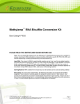
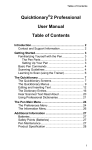
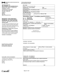
Audio Management System
User Manual
Version 1.1 (Build 9)
Digital Alert Systems
A division of Monroe Electronics
585-765-1155 | fax 585-765-9330
100 Housel Ave. | Lyndonville | NY | 14098
www.digitalalertsystems.com
Revision: 1.1 Publication: DASAMSMAN-0930
Copyright © 2011-2015 Digital Alert Systems, a division of Monroe Electronics Inc.
Information herein is considered accurate at the time of publication. We constantly strive to
improve our products and services therefore some specifications are subject to change
without notice. MultiPlayer and EAS-Net are trademarks of Digital Alert Systems and
Monroe Electronics. All other trademarks are property of their respective owners.
Digital Alert Systems
AMS Installation / Operation & Integration Guide
TABLE OF CONTENTS AUDIO MANAGEMENT SYSTEM INSTALLATION / OPERATION & INTEGRATION Introduction
How it works
Installation
3 3
3
4
CONFIGURATION STEPS 4 STEP 1. MULTIPLAYER — INSTALLATION AND INITIAL CONFIGURATION 5 MultiPlayer - Mounting
MultiPlayer – AMS Configuration Examples
MultiPlayer - Wiring
MultiPlayer - Audio Connections
MultiPlayer - GPI’s & GPO’s
MultiPlayer - Setting/Modifying IP Address
MultiPlayer - Resetting Default IP
MultiPlayer - Audio Port Configuration STEP 2. AMC — INSTALLATION AND INITIAL CONFIGURATION Mounting
Wiring
Configuring
AMC Menus Log In Screen
· AMC Configure > MultiPlayer
· AMC Configure > User
· AMC Configure > Playout
· AMC Configure > Sources
· AMC Configure > Channels
· AMC Configure > Network
· AMC Configure > TTS
· AMC Configure > Date/Time
· AMC Configure > System
· AMC Configure > GPIO
STEP 3 – DATA SOURCE CONFIGURATION WSI – Live:Wire™
WSI – TruAlert™
Newsroom Solutions – NewsTicker™
Business Technology Inc. - BTI
APPENDIX Changing PC Network Settings Specifications
Revision 1.1
5
5
6
6
6
7
7
8
9 9
9
9
9
9
11
11
12
13
14
15
16
18
19
20
23 23
24
24
25
29 29
30
Page 2 of 30
Digital Alert Systems
AMS Installation / Operation & Integration Guide
Digital Alert Systems Audio Management System
Installation / Operation & Integration
Introduction
The Digital Alert Systems (DAS) - Audio Management System (AMS) –
is designed as a simple solution for the “Twenty-First Century
1
Communications and Video Accessibility Act of 2010” (or simply
21CVAA) compliance, which requires television stations to provide audio
description in their Secondary Audio Program (SAP) channel to aurally
represent any “emergency information” appearing on the main channel.
This means any crawl or text displays on the main channel such as
weather alerts, emergency conditions, etc. – separate of actual
newscasts or EAS alerts – must be “voiced” on the SAP channel. In
!"#$%&'()*$+"*
,"-+)*
./"+&01#%-2)23
6%$<=$#>&?*577)*
!"#$"%&
"'()*$
%+,,-.+$
&*/01*22+1$
!"#$%3
%'2432-5+1$
4$51&6*"7*$8&9-25"
.:+)*)"&91$%"7&"*&9;:3
:)#"12$*<&9-25"&6*"7*$8
.:+)*)"&91$%"7&"*&9;:3
01#"8517&A$+$
.:)*5$%B&C4!B&)+#D3
4$51&@6'
4$51&6*"7*$8&9-25"&
.:+)*)"&91$%"7&"*&9;:3
:96&@6'
:)#"12$*<&9-25"&6*"7*$8
.:+)*)"&91$%"7&"*&9;:3
addition an “attention” signal or tone must be inserted on the main
channel to alert or indicate to viewers emergency audio is available on
the secondary channel.
Figure 1 Simplified AMS block diagram – incoming data is
converted to audio and played back on Main or SAP channels
The AMS is a two-part system consisting of a DAS Audio Message Controller (AMC) and its companion MultiPlayer™ whose
front panels are shown in Figure 2 and Figure 3 respectively; together provide proper message audio for both Main and SAP
audio streams. The DAS AMS is designed to aggregate information from a variety of sources, convert the text information to
audio using a high-quality Text-To-Speech (TTS) convertor, prepare it for playback on the different audio channels, then provide
audio and triggering signals on all configured channels under a single user interface.
Figure 2 Digital Alert Systems Audio Message Controller - Part 1 of the Audio Management System
Figure 3 Digital Alert Systems MultiPlayer™ - Part 2 of the Audio Management System
How it works
Both the Audio Message Controller and MultiPlayer are linked via a standard Ethernet (TCP/IP) network, which provides a
properly credentialed operator system configuration and control using any standard web-browser. Once configured the AMC
gathers emergency information from a variety of sources by monitoring network file locations or by other systems transferring
files to it then applying input filters to retrieve the appropriate information for text-to-speech conversion and subsequent queuing
and playout.
Besides actively monitoring data sources, an operator may load a pre-produced audio file, enter message text directly, or cut
and paste message text for automatic Text-To-Speech conversion. The AMC then handoffs the .WAV file, or the TTS audio file,
to the MultiPlayer readying it for playback.
1
http://www.gpo.gov/fdsys/pkg/BILLS-111s3304enr/pdf/BILLS-111s3304enr.pdf
Revision 1.1
Page 3 of 30
Digital Alert Systems
AMS Installation / Operation & Integration Guide
Once an audio message is loaded (queued) in the AMS the playback can be triggered in one of three ways;
1. Automatically - immediately after the audio message is loaded
2. By GPI trigger
3. By the operator clicking the "Play" button on the user interface.
There are three Audio Types defined by the AMC and managed by the MultiPlayer
Audio Type
Action
Main
Plays attention tone only
SAP (Secondary
Plays attention tone immediately followed by the alert text audio repeated the
Audio Program)
number of times defined in AMC. The attention tone is not repeated.
Preview
Provides an audio output for an operator to listen to the queued event without
attention tone, or interrupting either audio program streams. Very useful for
evaluating word pronunciations while modifying the TTS lexicon
Table 1 AMS Audio Type definitions
When activated, Main audio plays the preset attention tone then quickly returns to normal programming. The user can upload a
.WAV file of their liking perhaps a two-tone burst or a pre-recorded announcer indicating, “Additional audio information is
available on your secondary audio channel”, or use the default three tone alert programed with the unit.
Simultaneously the SAP (Secondary Audio Program) port is switched in and plays it’s audio message the two times as the rules
require, or a user defined number of iterations, after which it returns to normal SAP audio.
Installation
Each piece of the AMS it designed to be rack mounted in a standard EIA 19” rack assembly. The location of each unit is best
determined depending on the easiest location for wiring the various audio and video connections.
Configuration Steps
The installation and configuration will cover three major steps;
Step 1. MultiPlayer — Installation and initial configuration
Step 2. AMC — Installation and initial configuration
Step 3. Data Source Configuration
Each of these steps is covered in detail within the following pages. Additional information is also available in the Appendix and
on-line at www.digitalalertsystems.com
Revision 1.1
Page 4 of 30
Digital Alert Systems
AMS Installation / Operation & Integration Guide
Step 1. MultiPlayer — Installation and initial configuration
The Digital Alert Systems MultiPlayer (model DASMP) is uniquely designed four-channel (designated as Ports 1 thru 4) audio
player and program switcher. The MultiPlayer works in conjunction with the AMC to provide independent audio playout for up to
four discrete channels whose particular operating attributes are defined in the AMC. The four independent ports can be
configured for mono-analog or stereo AES and ports can be “bonded” or grouped together to create multi-channel audio
configurations described below. The MultiPlayer’s flexible design allows it to be configured to use its internal switching or
originate the audio signal(s) for switching or embedding by downstream devices, including independent GPO’s to trigger these
devices. The MultiPlayer features automatic program bypass in the event of power fail thus assuring the program input for any
port is automatically routed to the program output of the same port if there is loss of power or power supply failure.
For clarity the term Audio Signal refers to the physical nature of the signal i.e. (AES) digital audio or analog, while Audio Type
denotes the action that will be applied to the signal during playback.
MultiPlayer - Mounting
The MultiPlayer manages the audio and contact closure wiring; therefore to facilitate ease of wiring it should be placed in close
proximity to audio signal sources and control points. The unit is attached to a 19” EIA equipment rack using the standard
mounting holes on the front panel. Mounting screws are included in the shipping box.
MultiPlayer – AMS Configuration Examples
The Multiplayer features four Ports, each having an independent audio switch, four (4) GPI’s, and two (2) GPO’s. Based on the
required number of audio channels for the application each port may be used and configured in a different manner. Playback
control PLAY/PAUSE/STOP can be independently managed per port, however in the AMS application the incoming data is the
same for all ports and therefore creates the same audio file which is loaded into each channel.
For simplicity, it may be a good idea to wire the station’s Main program audio through Port 1 and the associated SAP channel on
Port 2. This is by no means the only configuration as there are a variety of ways the MultiPlayer and AMC can be configured to
manage different signal and source scenarios.
Local&Operator
Data$Layer$
Router
(Not&Included)
Signal$Layer$
Playback&Triggers&(OpConal)
Main&Program&Audio
(Stereo&Analog&or&AES)
DAS&AMC
Audio&
Message&
Controller&
DAS&MP
MulCPlayer&
Data$Layer$
MulCPlayer&used&for&signal&switching
Main&GPO
Main&Program&Audio&
(Stereo&Analog&or&AES)
SAP&GPO
Secondary&Audio&Program
(Stereo&Analog&or&AES)
Secondary&Audio&Program
(Stereo&Analog&or&AES)
Figure 5 AMS wired for program audio switching
Revision 1.1
Local&Operator
Incoming&Data
(Serial,&XML,&etc.)
Router
(Not&Included)
Signal$Layer$
DAS&AMC
Audio&
Message&
Controller&
DAS&MP
MulCPlayer&
Incoming&Data
(Serial,&XML,&etc.)
MulCPlayer&used&as&source
Main&GPO
Playback&Triggers&(OpConal)
Main&Program&Audio&
(Stereo&Analog&or&AES)
SAP&GPO
To&downstream&devices,
e.g.&embedders,&etc.
Secondary&Audio&Program
(Stereo&Analog&or&AES)
Figure 4 AMS wired for audio origination, triggering downstream
devices
Page 5 of 30
Digital Alert Systems
AMS Installation / Operation & Integration Guide
MultiPlayer - Wiring
MultiPlayer - Audio Connections
Audio connections are made to and from the MultiPlayer for each audio signal through the XLR connections on the ports labeled
1, 2, 3 & 4 as shown Figure 6. The AMS application does not require the Master Port and this port should remain unused.
Figure 6 MultiPlayer rear panel showing connections on Ports 1 -4. Master Port is not used
MultiPlayer ports are configured by selecting one of the standard audio signals then, under the AMC interface, selecting the
audio type. In this manner any port may be used for any audio signal as each port is configured for the audio type; Main, SAP,
or Preview in the AMC configuration. This allows mixing and matching any audio type across the four ports, which is especially
useful for stations with multiple Main and SAP channels.
Each of the MultiPlayer’s audio input/output ports can be configured to handle any one of these audio signals:
MultiPlayer Audio Signals (per port)
Designation
Description
AES3
AES digital with input (stereo pair) – locks to incoming AES signal for clock reference (Factory default)
ORIG
AES digital without input (stereo pair) – uses internal reference clock, generates AES silence when not playing
ANALOG
SLAVE
Analog mono – balanced audio input and output
Analog stereo – combination – ties playout with prior port ANALOG channel, creating an analog stereo pair.
Table 2 MultiPlayer supported audio signals and designations
From the factory each port is preset for AES audio signal pass-thru. This may be changed to reflect AES origination or analog
mono as explained in Audio Port Configuration section below.
MultiPlayer - GPI’s & GPO’s
The MultiPlayer features four (4) General Purpose Inputs and two (2) General Purpose outputs per each port. The table and
picture below define the wiring locations and the corresponding labeling in the AMC. These ports match the AMC configuration
settings in the Configure > GPIO menu.
Notes:
1. GPO’s are not grounded, having two connections (Pins 1 and 2).
2. The terminal strip is removable to facilitate ease of wiring.
Port 1- 4
Connection
Applies to all ports 1, 2, 3 and 4
Pin 1
GPO 1
Relay 1 Pin 1
Pin 2
Pin 3
Pin 4
Pin 5
Pin 6
Pin 7
Pin 8
Pin 9
Pin 10
GPO 2
GPI 1
GPI 2
GND
GPO 1
GPI 3
GND
GPO 2
GPI 4
Relay 2 Pin 1
Input 1
Input 2
Ground
Relay 1 Pin 2
Input 3
Ground
Relay 2 Pin 2
Input 4
Port Connection Example (Port 1 shown)
Table 3 MultiPlayer GPI & GPO connections. Port 1 shown as example - other ports follow same configuration.
Revision 1.1
Page 6 of 30
Digital Alert Systems
AMS Installation / Operation & Integration Guide
MultiPlayer - Setting/Modifying IP Address
The MultiPlayer ships with a factory default static IP Address: 192.168.0.220. To match a
station’s network configuration the IP address will most likely need changing which requires
initially logging in to the MultiPlayer at the 192.168.0.220 address to modify IP configuration.
(Additional information on configuring a PC network connection can be found in the Appendix.)
A CAT-5 network crossover cable is shipped with the MultiPlayer to allow direct connection from
a PC network interface to the MultiPlayer network port.
CAUTION: Before directly connecting a PC to the MultiPlayer always verify the cable is a
crossover by referencing the picture in Figure 7. Failure to use a crossover cable may either
Figure 7 Ethernet crossover cable
wiring diagram
cause the interface to not work, and one or both network ports may be damaged.
To assure a stable and steady connection with the AMC, the MultiPlayer should be configured with a static IP address. Consult
the IT department to determine the following information:
Static IP Address
Gateway
Subnet Mask
___.___.___.___
___.___.___.___
___.___.___.___
Use the following steps to modify MultiPlayer IP Address:
1.
2.
3.
4.
5.
6.
7.
8.
9.
Power up the MultiPlayer by inserting the AC cord and attaching to 100
– 240 VAC power source
While the MultiPlayer is booting (approximately 10 sec) open a web
browser on the PC
In the address line type 192.168.0.220 and press <Enter>. You should
be greeted with the MultiPlayer Home page as shown in Figure 8.
On the left side of the page click the TCP/IP Configuration link. The
screen should now display the TCP/IP configuration page as shown in
Figure 9.
Enter the previously obtained information for IP Address, Gateway
Address and Subnet Mask in the associated fields.
Click Save Changes to store the values
Figure 8 MultiPlayer Home page
Click Restart System with New Values will restart the MultiPlayer with the
new values.
Disconnect the network connection from the PC and plug into the network
switch/router
In a networked browser enter the new IP address to confirm connection.
The MultiPlayer’s home screen should appear.
MultiPlayer - Resetting Default IP
Figure 9 MultiPlayer TCP/IP Configuration screen
If necessary to reset the MultiPlayer to the default IP Address (192.168.0.220), press and hold the RESET button (located in a
recess on the back panel) for 10 seconds.
Reset button
(recessed)
Figure 10 MultiPlayer RESET button
Revision 1.1
Page 7 of 30
Digital Alert Systems
AMS Installation /Operation & Integration Guide
MultiPlayer - Audio Port Configuration
Once the MultiPlayer’s network configuration is complete the next step is to configure the audio signals to match the wiring
descibed above. The MultiPlayer can support different audio signals per port.
MultiPlayer Audio Signals (per port)
Designation
Description
AES3
AES digital with input (stereo pair) – locks to incoming AES signal for clock reference (Factory default)
ORIG
AES digital without input (stereo pair) – uses internal reference clock, generates AES silence when not playing
ANALOG
SLAVE
Analog mono – balanced audio input and output
Analog stereo – combination – ties playout with prior port ANALOG channel, creating an analog stereo pair.
Table 4 MultiPlayer supported audio signals and designations
Type the IP address of the MultiPlayer’s IP address into a
network connected web browser to display the MultiPlayer
home page.
Click Audio Port Configuration text link on the left to
navigate to the Audio Port Configuration page.
In the factory configuration, all channels are set as AES
digital channels. Each port operates independently and is
not bonded to another port.
The current signal type for each port is shown in the text
below Chan x: (where “x” is the associated port number).
To change audio signals use the pull down menus as
shown under Port 1 to the right. Refer to Table 4
MultiPlayer supported audio signals and designations for
more information about each selection.
In the analog mode each port is a single audio channel. to
create a stereo pair, select, Port 1 as “ANALOG” and Port
2 as “SLAVE”. This forms a bonded pair for Left and Right
audio. Similarly setting ports 3 & 4 in the same way
creates a second stereo analog pairing forming a second
bonded pair.
NOTE: The “SLAVE” option in only selectable for
Ports 2 and 4
IMPORTANT NOTE: Selections must be made for each Port regardless if they differ with the current settings.
Once a selection has been made for all of the ports, click on Save Changes. To ensure all settings have saved, click the
Refresh button. If the configuration remains as desired the settings have been properly stored. If not repeat the selection of
each port as outlined above.
Revision 1.1
Page 8 of 30
Digital Alert Systems
AMS Installation /Operation & Integration Guide
Step 2. AMC — Installation and Initial Configuration
Figure 11 AMC - Audio Message Controller - Front Panel
Figure 12 AMC - Audio Message Controller - Rear Panel
Mounting
The AMC can be easily mounted in any standard 19” equipment rack. Device location is very flexible as it usually only requires
AC Power and a network connection able to reach the same network as the associated MultiPlayer. If the USB serial ports are
used (rarely) the distance to the serial data source should be taken in account making placement more distance critical.
Wiring
Connect the AMC to the same network as the MultiPlayer. Provide AC power.
Configuring
The AMC is initially configured with both factory default static IP Address at 192.168.0.210 and DHCP client for network
administrators wishing to manage DHCP access to these devices. The media access control address (MAC address) is printed
on the rear panel of the device, so network administrators may assign a specific IP address to the unit through the network
DHCP server. Please contact your network administrator if you have questions regarding your network connections.
AMC Menus
Log In Screen
From a web browser type the IP address of the AMC (default is 192.168.0.210) and press Enter. The log in screen as shown in
Figure 13 should appear.
If the page does not appear it may require entering the full path http://xxx.xxx.xxx.xxx or the secure version
https://xxx.xxx.xxx.xxx where xxx.xxx.xxx.xxx is the AMC’s IP address in order to gain access.
When using https:// a prompt may ask about the security certificate to allow access. Simply respond in the affirmative.
Default
(Case sensitive)
Username
admin
Password
password
Figure 13 AMC Log In screen
Revision 1.1
Page 9 of 30
Digital Alert Systems
AMS Installation /Operation & Integration Guide
AMC Home Screen
The AMC provides a very simple screen layout with three primary menus; Home, Logs, and Configure in the top menu bar.
Other areas of the Home screen are highlighted below.
1.
Top Menu Bar
2.
Name of logged in user
3.
Log Out link
4.
Channel Expand/Collapse
5.
Master controls
6.
Individual channel status and controls (when
expanded)
7.
TTS Data field shows any text currently in the
queue for playout. User text is also entered here.
8.
System Summary indicating playout in Manual
operating mode. Clicking > expands the selection
providing more details
9.
Alert Queue with number of audio messages
currently in the queue. Clicking > expands the
selection providing more details
10. MultiPlayer status indicator indicating the AMC is
properly communicating with the device. Clicking
> expands the section providing individual GPI
and GPO status.
Expanded Home Screen
The Home screen can be expanded to provide more details and controls as explained below.
1.
Expanded channel controls for access to
individual channel controls. Clicking the
icon
will expand or collapse the individual channel
controls. Clicking the
image expands and
collapses all channel controls.
2.
Expanded Alert Queue showing the number of
items in the queue. Clicking the
button
removes all items from the queue.
The TTS Data field displays the current text
during playout and can be used to enter usergenerated text by clicking in the field then typing
or cut and paste the desired text for conversion.
When editing the field will highlight and two
buttons
and
appear.
Clicking Update will return to display whatever is
active while it converts the text to audio. When
the TTS is completed the Alert Queue will update
and the text will appear during playout. Cancel
will ignore any input and return.
3.
Expanded System Summary features
information on several system parameters.
Clicking the
button allows Admin users
access to the Configure menus.
4.
Revision 1.1
Expanded MultiPlayer GPI/O status screen. Each
GPI and GPO is displayed with a red or green
status indicator. Green indicates active - input is
closed, output relay is closed). Red indicates
inactive - no input and output relay is open. Each
indicator can be labeled and it’s operation
defined in the Configure > GPIO menu.
Page 10 of 30
Digital Alert Systems
AMS Installation /Operation & Integration Guide
Setting MultiPlayer Connection
•
AMC Configure > MultiPlayer
1.
Click Configure on the top menu bar, then click
the MultiPlayer tab
2.
In the field MultiPlayer IP Address enter the
proper address of the MultiPlayer
3.
In MultiPlayer Username enter: guest
4.
In MultiPlayer Password enter: guest
5.
Click Save
The indicator dot
to the left of the word “Online”
should turn green indicating the AMC and MultiPlayer
are now paired.
If the indicator remains red assure the IP address is
correct and the spelling of either the Username or
Password is correct (no spaces before or after)
Clicking the blue text MultiPlayer Audio Port
Configuration will open another window to the
MultiPlayer configuration menu.
Adding/Deleting Users
•
AMC Configure > User
The AMC allows multiple simultaneous access for review or operational control. Users are afforded one of two levels of
Privileges. Users with Admin privileges have complete access with permission to make modifications and configuration
changes. User level privileges provide complete playback control, text entry and log access, but are not allowed in the Configure
menu. An admin can easily grant or deny users access by simply checking or unchecking the Enabled box in their respective
row.
1.
Click Configure on the top menu bar, then the
User tab. (The user admin is preloaded into the
system)
2.
To add a new user click the + button in the left
margin - a new sub page will appear.
3.
Enter the appropriate information in each of the
fields; Username, First Name, Last Name. Enter
a password recognizing it must be at least 6
characters in length. Select the user’s Privilege
via the pull-down menu– either Admin or User.
(Note: Once created a username cannot be
changed. To modify a username, create a new user
with the desired username then delete the old
account.)
4.
Click Save to store the information
5.
To remove a user, click the - button in their
respective row. A popup box can either confirm or
cancel the deletion.
(Note: The admin account cannot be deleted.
Users can be activated or deactivated by
checking or clearing the box next to their name.
Revision 1.1
Page 11 of 30
Digital Alert Systems
AMS Installation /Operation & Integration Guide
Setting Playback Controls
•
AMC Configure > Playout
The System menu set three operational parameters, the Play Mode, the number of Play Loops and the Attention audio.
The Play Mode defines how the system will respond to data inputs. In the Manual mode audio message will be queued in the
order receive, but will not play unless a user specifically clicks the Play or Play All buttons on the Home screen. When set for
GPI mode playback response is governed by a GPI to trigger playback. Under Auto the system will play a message immediately
upon conversion without waiting for an operator or GPI trigger. Regardless of the selected mode an operator always has
override permissions over playback, pause, or stop.
The Play Loops parameter sets the number of iterations the message audio will play on a SAP configured channel. Note: as of
this writing the 21CVAA rules require message audio be played at least twice after the attention message.
The Attention area shows the audio file currently set and in use. The attention file will play on all Main and SAP configured
channels. For a Main channel only this file will interrupt the programming, on a SAP channel the attention file will play first
followed by the audio message for the number of times set in Play Loops. The Attention file can be changed by clicking the
Choose File button and select a new attention file.
To accept any changes to this menu click the Save button.
2
1.
Assign the Play Mode using the pull down menu
for Manual, GPI, or Auto (see text for more
information)
2.
The value in Play Loops field indicates the
number of times the audio message will play on
a SAP configured channel.
3.
Just right of Attention is the audio file name set
as the attention tone. To change click
2
Choose File and select a new file . The new file
name will now appear.
4.
To accept any changes to this menu click the
Save button.
For proper playback the attention tone must be a 16KHz sampled 16-bit.WAV, mono format file.
Revision 1.1
Page 12 of 30
Digital Alert Systems
•
AMS Installation /Operation & Integration Guide
AMC Configure > Sources
The AMS interfaces with a number of different data sources (see STEP 3 – Data Source Configuration below). Some sources
communicate to watch folders in the AMC, while others rely on external watch folders. The Sources tab provides configuration
adjustment for external watch folders.
The AMC establishes a File Transfer Protocol (FTP) link with
the external folder and then periodically checks the
designated files in the folder for changes. If the file contents
have changed the AMC will then process the new information.
(Presently this is only available for setting NewsTicker values.
Future versions are intended to support other interfaces)
Initially or, if no external watch folder sources are configured
the display starts as shown in Figure 14.
Figure 14 AMS Source configuration initial screen
Clicking + Add Source will open additional window for
editing/modifying the links to the external watch folders.
1.
In the Type field the pull-down selects an
available interface type automatically filling the
other fields with standard presets.
2.
The Name field is used to create a unique
designation for the interface and will appear in a
list in the left most columns.
3.
Just right of Attention is the audio file name set
IP Address - the network reachable IP
address of the watch folder.
b. Username - the watch folder ‘s login name
c. Password - the watch folder’s login password
d. Source Directory - the watch folder’s file
path, where source XML files are
stored/updated. Be sure the pathname is
complete including any “/” characters.
a.
4.
File Names – The AMC is able to monitor
multiple files in a watch folder. Simply list all
monitored filenames separated by a space. e.g.
“breaking.xml” or “breaking.xml closings.xml”
5.
To accept any changes to this menu click the
Save button.
Sources may be enabled or disabled using the check box alongside the name in the leftmost column. In this way an operator
can control access or the specific files/folders the AMC will monitor for source data.
Revision 1.1
Page 13 of 30
Digital Alert Systems
AMS Installation /Operation & Integration Guide
Setting Channels
•
AMC Configure > Channels
The Channels menu links the MultiPlayer Port with the Audio Type or action
desired for that port. Together with MultiPlayer’s Audio Port Configuration, which
sets the audio signal, the Channels menu defines the playback manner of each
port.
Selecting/de-selecting the box in the Enabled column will turn on or of the
respective channel. When updated these changes are reflected on the Home
screen.
The Name field allows a channel to be labeled with the information entered here
being displayed on the Home screen, therefore it is a good idea to use a station’s
ID along with the type of channel to better understand the action a user should
expect on that channel. For example entering WQRR-Main for the Main channel,
or WQRR-SAP for the secondary audio channel would let a user on the Home
screen
1.
Click Configure on the top menu bar, then the
Channels tab. (the default values are preloaded)
When updated changes are reflected on the
Home screen as indicated in by the boxes.
2.
Selecting/de-selecting the box in the Enabled
column will turn on or off the respective channel.
3.
Enter any descriptive text in the Name text box.
Best practice is to enter a station’s call letters.
4.
Using the pull-down menu select the Audio Type
– either Main or SAP. (defined in Table
above.)
5.
Revision 1.1
1
Click the Save button to save any changes.
Page 14 of 30
Digital Alert Systems
AMS Installation /Operation & Integration Guide
Setting Network
•
AMC Configure > Network
As previously mentioned, the AMC is factory configured with both a default IP Address at 192.168.0.210 and DHCP client. For
network administrators wishing to manage DHCP access the media access control address (MAC address) is printed on the
rear panel of the device. With this information a network administrator may assign a specific IP address to the unit from the
network DHCP server.
The current network settings will be displayed in the individual fields when this menu is opened. Modifying the IP address and
other network parameters will over-ride the current settings.
CAUTION: Improper or incorrect settings may result in no access and restoring the default settings may be the only way to
regain access to the unit.
Setting a Static IP Address
1.
Using the Configure IPv4 pull-down menu select,
Manual. The other fields are now editable
(Values shown at right are examples only and
may not reflect the required network values)
2.
Enter the IP Address, the Subnet Mask, the
Gateway (Router) and any DNS Servers.
Multiple entries should be separated with a
space. Note: Several features require Internet
access making these entries important to overall
operation.
3.
(Optional): Enter any Search Domains the AMC
should look for simple or directed resolution.
Not required for standard AMC operation.
4.
To accept changes click the Save button. The
system will immediately use the new settings,
this may require changing the web address or
refreshing the page.
Using DHCP for IP Addressing
If the AMC found a DHCP server at start up those values would be shown in their respective fields. If there was no server or the
unit is switched to Manual the DHCP client shuts off. To use a DHCP server to assign networking values:
1.
Select DHCP from the Configure IPv4 pull-down
menu.
(Values shown at right are examples only and
may not reflect the required network, moreover
any information displayed without an input box
were received from the DHCP server and are
non-editable)
2.
Click the Save button.
The system will immediately use the new
settings. This may require changing the web
address or refreshing the page..
3.
4.
(Optional):
Enter any additional DNS Severs or Search
Domains in their respective fields. Multiple
entries should be separated with a space.
Click the Save button
Not required for standard AMC operation.
Resetting to default IP
If necessary please contact the factory for information on resetting the default IP ([email protected])
Revision 1.1
Page 15 of 30
Digital Alert Systems
AMS Installation /Operation & Integration Guide
Setting Text-To-Speech Options
•
AMC Configure > TTS
This menu is used to select the TTS voices used for text conversions, in addition to adding, deleting or modifying a particular
voice’s lexicon. The AMS features the standard “Callie” voice Text-To-Speech (TTS) engine and any future voices available for
purchase and inclusion into the system.
The TTS engine uses a lexicon file for special instructions on how to “speak” a word or phrase in a particular way. For example
the word “wind” can be pronounced both as “wīnd“ with a long “I” sound meaning to coil or wrap something, or “w-eh-nd”, as in
a High Wind Warning. Also the text abbreviation “T-Storms” may be used as an abbreviation for the word “Thunderstorms”.
Adjusting the lexicon can greatly improve the way a TTS system understands and voices these types of words. Along with
being able to control individual words, Pitch and Speed parameters allow global adjustments to how the system speaks all text.
There are a number of “test” buttons to sample any additions or modifications thus allowing a user to very closely refine how the
system will speak any text.
Revision 1.1
1.
The standard TTS voice is “Callie” a female US
English voice standard on all AMC’s. Additional
2.
The fields for Voice, Language are preset, as
well as the licensing fields for the standard voice.
These are grayed out and non-editable.
3.
Clicking the Options button near the bottom will
expand the screen to reveal additional settings
for controlling the text-to-speech playback.
1.
The screen displays the lexicon table of uniquely
pronounced words or abbreviations. Each item
consists of two fields: Literal and Pronunciation
where Literal is the exact text of the word or
abbreviation being defined, and Pronunciation is
a list of "phonemes" which represent how to
pronounce (voice) the word. The value in the
upper right corner indicates the number of
entries in the table.
The word “T-Storm” is presented as a commonly
used example. When the AMS “sees” the
abbreviation it will speak it as “thunderstorm”
described by the phoneme list to the right.
2.
The Voice section allows for both Pitch and
Speech Rate controls for fine-tuning the voice.
The default values are “0” for Pitch and “6” for
Speech Rate. Adjusting these sliders acts
globally affecting the entire speech playback.
3.
The Test area lets users create a sample
sentence or words to test the settings of the
speech engine before committing to the
changes. Typing in the text field then clicking
the right-facing triangle at the end of the line will
create a sample audio file that will play on
properly configured browsers. Note: It can take
several seconds to create the example audio
playback so be patient.
Page 16 of 30
Digital Alert Systems
AMS Installation /Operation & Integration Guide
1.
To add a new lexicon entry click the Add
button and the screen will expand with two text
entry boxes for Literal Text and Pronunciation.
2.
Type the word or abbreviation in the Literal Text
entry field. There is no regard for capitalization,
so Wind, WIND, WinD would all be spoken the
same.
3.
In the Pronunciation field enter the phonemes to
create the sounds the TTS engine will use to
speak the word.
There is a great deal of information available as
well as a number of important examples for
creating a proper phonemes list by clicking the
Help button.
Note: It takes time and practice to properly
create the right set of phonemes and incorrect
values will cause the system to simply use the
default pronunciation for that word.
4.
When done click the Add button to save the
entries.
1.
The lexicon table will be updated and the
numeric indication incremented.
2.
To review or preview the sample highlight the
text by hovering over the line then click the
triangle “play” button on the right.
3.
After a few seconds an audio player control will
appear at the bottom and the word or
abbreviation text will be played through the
browsers speakers. The selection can be
repeated by clicking the play button on the audio
control panel.
4.
To edit or modify the lexicon entry simply click
the line and the entry lines will reappear. Make
any changes then click the Update button to
save the entries. This must be done each time a
change is made in order to properly store the
modified values.
5.
Clicking the play arrow on the lexicon line will
create a new audio preview using the changes
6.
The Test area can accept a full string of text
allowing a user to preview how a word or an
entire sentence, or phrase may be voiced,
including any changes in Pitch or Speech Rate.
Note that any changes require clicking the play
triangle at the end of the text line to create an
updated audio preview.
Scroll down for phoneme examples
Revision 1.1
Page 17 of 30
Digital Alert Systems
AMS Installation /Operation & Integration Guide
Setting Date & Time
•
AMC Configure > Date/Time
The Date/Time functions provide proper time/date stamping of files and logs within the AMS. The system can be run on an
internal clock, or synchronized to a Network Time Protocol (NTP) server via the network connection.
Revision 1.1
1.
Selecting the Set Time/Date using Network Time
Protocol (NTP) Server check box will activate
synchronization with the NTP server defined in
the field. The north-america.pool.ntp.org
server is one of many available via the Internet.
2.
To change NTP servers, enter the address in the
associated field. (Note: If the NTP is an Internet
name the network settings must have a DNS
location for proper address resolution)
• A red indicator
is displayed if the NTP
connection is severed or unreachable.
• An orange
indicates the AMC is sync’ing
with the selected NTP server. Recognize it may
take up to 10 minutes to sync.
• Green
means the AMC is connected and
synchronized with the selected NTP server.
3.
Using the Time Zone pull-down select the
location to properly adjust the time offset for all
records and logs. In other words, changing the
Time Zone will reflect in the logged time stamps.
4.
To accept any changes click the Save button.
Page 18 of 30
Digital Alert Systems
AMS Installation /Operation & Integration Guide
Installing Updates
•
AMC Configure > System
The AMC Configure > System page shows several pieces of hardware and software information currently running on the AMC.
The system uses a simple Internet based updating mechanism that requires Internet access to the Digital Alert Systems/Monroe
Electronics update server. Updates are not “pushed” to the AMC, rather they are only available on “demand” by an admin
operator. This means an admin level operator must click the Check for Updates for the system to contact the update server to
see if any updates are available. In addition there is a Remote Support slider switch, which an admin can activate, allowing
linked access to the Digital Alert System customer support network. This feature provides a mechanism for greater detailed
support and evaluation, however should only be enabled when requested by DAS technical support.
1.
Remote Support slider switch activates linked
access to the Digital Alert System customer
support network. This feature provides a
mechanism for greater detailed support and
evaluation, however should only be enabled
when requested by DAS technical support.
2.
Clicking the Check for Updates button instructs
the AMC to check the Digital Alert Systems
server for any updates.
1.
The current status of each element will be
displayed on an Updates pop-up. The current
version and the latest version of each part of the
system is displayed
2.
If any new updates are available the display will
indicate so in the tabular form shown at left.
3.
If all versions are current or to ignore any
updates click Cancel
4.
To update any one or all of the components
select the checkbox under Package on the
associated line, and then click the Update
button.
If the Updates page shows more than one
module available it is generally advised to check
them all to assure the OS and Applications
remain synchronized. Some features or functions
may not operate properly if only a single
package is updated.
IMPORTANT: An App update requires a manual
browser page ‘refresh’ and an OS update
requires a manual reboot after closing the
update dialog for changes to take effect.
Revision 1.1
Page 19 of 30
Digital Alert Systems
AMS Installation /Operation & Integration Guide
1.
The display will expand to show the download
and updating progress as seen in the example
on the left.
2.
Once the download and update is complete the
screen will refresh with the latest information.
3.
In those cases where a reboot is required it will
display the log in screen.
Setting General Purpose Inputs and General Purpose Outputs
•
AMC Configure > GPIO
The AMS provides a number of General Purpose Inputs and General Purpose Outputs using the GPIO connections on the
MultiPlayer (see Table 3 MultiPlayer GPI & GPO connections. Port 1 shown as example - other ports follow same
configuration.) Each GPI and GPO features mnemonic area allowing each input or output to be labeled thereby making it easy
to identify which device is either sending or receiving the intended signal. These labels and the current state are also shown in
the MultiPlayer expanded view on the Home screen.
Revision 1.1
1.
Each of the GPI’s and GPO’s can be labeled by
editing the text box above each of the pull down
menus
(Values shown at right are examples only and
may not reflect the required or desired
configuration)
2.
Using the pull down menu select the desired
action for each of the GPI’s and GPO’s. The
actions for each function are described in the
tables 6, 7 & 8 below.
If there is no action required leave the action in
the default states of Ignore for GPI or Disabled
for GPO.
3.
To accept any changes click the Update GPIO
button, or to ignore /discard any changes click
the Clear / Reset All button.
Page 20 of 30
Digital Alert Systems
AMS Installation /Operation & Integration Guide
GPI/O Prioritization
•
When an alert is ready to play, any GPO’s designated “Cued” will close prior to play.
•
Playout can be started manually (Manual), immediately (Auto), or by GPI according to the Play Mode (which is set
in Configure > Playout).
•
The alert remains active until it has played on all configured channels at which point all the GPO’s will open.
•
Regardless of playout mode, the operator can always manually control playback with the UI buttons.
•
Multichannel GPI control can create ambiguous inputs conditions. For example, if one input has Play All ‘on’ and
another input has Stop All ‘on’, they clearly conflict. In cases where multiple conflicting GPIs are present
simultaneously, the AMC use the following prioritization:
Priority
1
2
3
4
5
6
7
8
9
GPI Input
Disable Channel - channel will ignore GPI inputs.
Play/Pause Channel
Rewind Channel
Stop All
Play/Pause All
Play All
Pause All
Rewind All
Next All
Table 5 GPI Prioritization shown in order
Channel controls take precedence over global controls. In another example, if a Play All is ‘on’ for one input and a
Stop Channel is also ‘on’, the Stop Channel takes precedence over the “All” command and that channel will stop
playout.
•
Other notes
o
o
o
o
o
A channel may be switched off at any point. If anything is playing when it is switched off, that channel will
stop play, pulse any Momentary @ End GPO’s and leave all assigned GPO’s open
While switched off, the channel will display in gray on the UI. If a channel is switch back on while an alert
is ready, the channel will cue any “Cued” GPO’s and remains in a Stopped state.
Any time ‘Stop’ is pressed (either the channel or Stop All), any “Cued” GPO’s for the channel(s) will be
closed. In this manner the “Stop All” function has the effect of resetting to the beginning of alert.
GPO’s now follow each channel independently meaning GPO ‘duration’ will be closed for the specific
channel as long as it’s playing/paused.
Any GPO’s designated “Momentary” will pulse close for roughly 200ms, then open again.
Global Commands –
Controls all channels
Stop All
Play All
Pause All
Play/Pause All
Rewind All
Next All
Stops playback on
all channels, opens
any GPO’s and
returns to program
audio
Active input causes
all channels to Play
audio at top of
queue
Active input high will
pause all playing
channels. Active
GPO’s remain
closed. Audio output
is silent.
Active input causes
all channels to Play
All, Deactivated will
Pause All channels.
Active input will
return playback to
the beginning of
current file, and
Pause All.
Active input will
cause playback to
jump to next item in
queue.
Table 6 AMC GPI Global Commands
Revision 1.1
Channel Commands –
Individual channel controls
Stop Channel
Play/Pause
Channel
Rewind Channel
Disable Channel
Ignore
GPO Settings
(assigned by Port)
Halt playback on
individual channel,
opens any GPO’s
for the assigned
port and returns to
program audio
Active input
causes assigned
channel to Play,
Deactivated will
Pause All
channels.
Active input will
return playback to
the beginning of
current file, and
Pause.
Turns off channel
and inhibits any
playback or
function.
Ignores any GPI
state
Table 7 AMC GPI Channel Commands
Duration
Cued
Momentary
@ Start
Momentary
@ End
Disabled
Closed while the
channel is playing
audio
Channel is loaded with
audio and ready for
playback
Pulses closed for xx
ms at the beginning of
playback for edge
triggered devices
Pulses closed for xx
ms at the end of
playback for edge
triggered devices
GPO remains open
regardless of any
operation
Table 8 AMC GPO Options
Page 21 of 30
Digital Alert Systems
AMS Installation /Operation & Integration Guide
1.
Each of GPI and GPO can be labeled by clicking
and typing in their respective Name box(es)
2.
Using the pull-down menu select the desired
operation or function. The Ignore and Disabled
functions can be used to shut off operation
without having to disconnect any wires.
3.
To accept any changes to this menu click the
Save button, or to
ignore /discard any changes click the Clear / Reset All
button
Revision 1.1
Page 22 of 30
Digital Alert Systems
AMS Installation /Operation & Integration Guide
STEP 3 – Data Source Configuration
This section outlines the configuration steps for several of the most common data sources providing information to the AMS for
processing. If the source is not shown please contact the factory for additional information.
WSI – Live:Wire™
Data Type:
Connection:
Overview:
Configuration Steps:
Customer Support:
XML
Network connection via FTP to AMC
The WSI – Live:Wire system is configured to produce an XML file output of the
crawl text that is directly transferred to the AMC over a network using FTP.
Configuring the Live:Wire system is straightforward is very simple for an
operator to configure.
1. Open the Live:Wire application
2. Locate the output settings area as shown in Figure 15
3. Select the check box “Output Crawl to XML via FTP”
4. Enter the IP address of the AMC in the FTP Site box
5. Enter /incoming/wxxml.xml in the Destination File box. Note
capitalization and forward slash are important. Assure there are no
spaces before or after
6. Enter anonymous in the Username box
7. Enter anonymous in the Password box. You will not be able to see
the letters, so be sure the spelling is correct. Again, assure there are
no spaces before or after.
8. Configuration complete
Tel: +1 (978) 983-6351
IP Address of AMC (Address
shown is example only)
Figure 15 WSI – Live:Wire configuration page.
Revision 1.1
Page 23 of 30
Digital Alert Systems
AMS Installation /Operation & Integration Guide
WSI – TruAlert™
Data Type:
Connection:
Overview:
Configuration Steps:
Customer Support:
ASCII Text
Network connection via FTP to AMC
The WSI – TruAlert system is configured to produce an ASCII file output of the
crawl text, which is directly transferred to the AMC over a network using FTP.
Configuration requires WSI customer support .
1. Contact WSI TruAlert customer support (see number below)
2. Indicate the system needs be configured to FTP the crawl text to the
AMS.
3. They will load and run a script on the local machine to configure the
transfer then add the System settings to complete the link.
System settings
Host: xxx.xxx.xxx.xxx (IP Address of the AMC)
User: anonymous
Pass: anonymous
Dir: /incoming/yyyy where yyyy is the file name
Tel: +1 (978) 983-6351
Newsroom Solutions – NewsTicker™
Data Type:
Connection:
Overview:
Configuration Steps:
Contact Information:
XML
Network connection from NewsTicker to AMC via FTP push
The NewsRoom Solutions NewsTicker product creates one or more XML files
storing them in a specific directory. The files correspond to the subscribed
modules for breaking news, severe weather, or school closings.
The Newsroom Solutions support team must complete initial configuration.
They create the specific directory and file exports on their system necessary for
the AMC to “grab” and process the audio matching the crawl presentation. At
setup conclusion the following information will be completed:
Host: xxx.xxx.xxx.xxx (IP Address is site specific)
User: tts
Pass: muAk7tfP
Dir: home/tmp/out/
File(s): breaking.xml
closings.xml (Optional – dependent on station config.)
severewx.xml (Optional – depends on station config.)
Newsroom Solutions Client Support Center
(704) 665-5300 x2
Business Hours
Mon - Fri, 9:00 AM - 5:00 PM ET
Non-Emergency
[email protected]
Emailing automatically opens a ticket and returns to you a ticket number
used to track your matter through resolution.
Revision 1.1
Page 24 of 30
Digital Alert Systems
AMS Installation /Operation & Integration Guide
Business Technology Inc. - BTI
Data Type:
Connection:
Overview:
Configuration Steps:
ASCII (UTF-8) text file
Network connection - BTI Attendant Solutions to AMC via FTP push
The BTI Attendant Solutions creates an ASCII text output mirroring the text sent
to the various character generators. When information is updated the system
“pushes” the text file into the AMC for subsequent Text-To-Speech conversion
and loading in to the respective MultiPlayer channels for playout.
The system may also be linked with a GPO from the BTI Attendant Solutions
to invoke audio playback in relative synchronization with the text playout.
Initial configuration must be completed by BTI to properly set the system to
transfer file(s) to the AMS (please refer to the contact information below). Once
this is completed the station should proceed with additional setup steps as
outlined below.
BTI Breaking News Alerts
Stations using BTI for breaking news alerts will get the new transmission
NU902 (see the yellow highlight in Figure 16). To produce text this may run
stand alone, or BTI can program it into the current broadcast Breaking news or
Amber alert transmission.
Figure 16. BTI Transmission Status screen showing job NU902.
1.
To configure the NU902 breaking news transmission, from the
Transmission Status screen click the Configure
button shown in
Figure 16.
Figure 17. Configure Job NU902 screen with number of Cycles highlighted
2.
On the Configure Job NU902 screen set the number of cycles to run the
transmission. Typically this has a value of 2 as shown in Figure 17.
3.
Click Save then Close
4.
After returning to the Transmission Status screen click the Content
button.
(continued)
Revision 1.1
Page 25 of 30
Digital Alert Systems
AMS Installation /Operation & Integration Guide
5.
In the Maintain
Transmissions
page click
Customize to
enter the
Advanced
Transmission
parameters.
The Customize section
of the system contains
the additional setup
parameters. The
appropriate Value
Figure 19 Maintain Transmissions screen for
fields in the Advanced
breaking news
Transmission
Parameters screen
should be changed as required.
Figure 18 BTI Advanced
Transmission Screen for setting IP
path to AMC. (Note the address
192.168.0.68 is shown as an
example only. Also note the forward
slash / separating the IP and the
folder name “incoming”)
6.
Full pathname of ftp Site: Enter the full path to the AMC in the form of
xxx.xxx.xxx.xxx/incoming where the x’s represent the AMC’s IP
address.
7. filename (no Extension): Default = Alert. Can be modified if necessary,
otherwise leave as default value.
8. ftp User login: Default = anonymous. Can be modified if necessary,
otherwise leave as default value.
9. ftp User password: Default = anonymous. Can be modified if
necessary, otherwise leave as default value.
10. Contact to close to play alert tones (0-7): User selectable. Stations
using the BTI Contact Closure (GPO) unit may choose an open contact to
wire to the MultiPlayer to control audio playback
Optional GPI/O wiring to the AMC:
A. Wire (2-wires) the selected GPO from BTI Attendant Solutions to
one or more of the GPI’s on the MultiPlayer.
B. In the AMC Configuration > GPIO page assign the input to “Play
All” (Note you can label the input “BTI” making it easy to identify
the input source)
C. Click “Update” to save the configuration
11. number of seconds to keep the contact closed: Default = 60. Can be
modified if necessary, otherwise leave as default value
12. Click Close then Close again.
Revision 1.1
Page 26 of 30
Digital Alert Systems
AMS Installation /Operation & Integration Guide
BTI Weather Alerts
Stations using BTI for weather alerts will get the new Transmission EW903 (see
the yellow highlight in Figure 20). To produce text this may run stand alone, or
BTI can program it into the current broadcast weather alert transmission.
1.
To configure the EW903 weather transmission, from the Transmission
Status screen click the Configure
button
Figure 20. Transmission Status screen showing weather alert job EW903
2.
On the Configure Job EW903 screen set the number of cycles to run the
transmission. Typically this has a value of 2 as shown in Figure 21.
Figure 21. BTI Configure Job EW903 screen with number of Cycles highlighted.
3.
Click Save then Close
4.
After returning to the Transmission Status screen click the Content
button.
Figure 22 BTI Maintain Transmissions screen
5.
In the Maintain Transmissions page click Customize to enter the
Advanced Transmission parameters
(Continued)
Revision 1.1
Page 27 of 30
Digital Alert Systems
AMS Installation /Operation & Integration Guide
The Customize section of the system contains the additional setup
parameters. The appropriate Value fields in the Advanced Transmission
Parameters screen should be changed as required.
Figure 9. BTI Advanced Transmission Screen for setting IP path to AMC. (Note the
address 192.168.0.68 is shown as an example only. Also note the forward slash /
separating the IP and the folder name “incoming”)
6.
Full pathname of ftp Site: Enter the full path to the AMC in the form of
xxx.xxx.xxx.xxx/incoming where the x’s represent the AMC’s IP
address.
7. filename (no Extension): Default = Alert. Can be modified if necessary,
otherwise leave as default value.
8. ftp User login: Default = anonymous. Can be modified if necessary,
otherwise leave as default value.
9. ftp User password: Default = anonymous. Can be modified if
necessary, otherwise leave as default value.
10. Contact to close to play alert tones (0-7): User selectable. Stations
using the BTI Contact Closure (GPO) unit may choose an open contact to
wire to the MultiPlayer to control audio playback
Optional GPI/O wiring to the AMC:
A. Wire (2-wires) the selected GPO from BTI Attendant Solutions to
one or more of the GPI’s on the MultiPlayer.
B. In the AMC Configuration > GPIO page assign the input to “Play
All” (Note you can label the input “BTI” making it easy to identify
the input source)
C. Click “Update” to save the configuration
11. number of seconds to keep the contact closed: Default = 60. Can be
modified if necessary, otherwise leave as default value
12. Click Close then Close again
Contact Information:
Business Technology Inc. BTI
[email protected]
+1 (615) 591-1900 Ext 701
Business Hours
Mon - Fri, 8:00 AM - 5:00 PM CT
[email protected]
Revision 1.1
Page 28 of 30
Digital Alert Systems
AMS Installation /Operation & Integration Guide
Appendix
Changing PC Network Settings
To change the MultiPlayer’s IP address you will need a computer whose IP settings can be modified. The following instructions
3
are for a PC running Windows™ 7 .
1. On the computer open Control Panel, then open
Network and Internet. Right-click on the desired network
connection, then select Properties.
2. From the Local Area Connection Properties screen
highlight by clicking Internet Protocol Version 4 (TCP/IP)
then the “Properties” button.
(Helpful advice: Note the current settings on this page
BEFORE making any further changes to reset the
computer back to the original values.)
3. Next click the radio button for Use the Following IP
Address.
4. In the “IP Address” field enter 192.168.0.200
5. In the “Subnet Mask Field” enter 255.255.0.0
Leave the “Default gateway”, “Preferred DNS server” and
“Alternate DNS server” fields blank.
Click OK.
6. Connect the crossover cable between the MultiPlayer
and/or the AMC and the computer
3
Other versions of Windows have screens with equivalent operation, but different names, additionally a Macintosh computer may also be used by modifying similar
settings in System Preferences > Network
Revision 1.1
Page 29 of 30
Digital Alert Systems
AMS Installation /Operation & Integration Guide
Specifications
AUDIO MESSAGE CONTROLLER
LAN Interface: TCP/IP Ethernet
•
•
•
•
One (1) 10/100BASE-T Ethernet IEEEE 802.3
RJ-45 connectors suited for wiring CAT-5 or above
Port features link & data indicators
Assignable IP addressing (unit ships fixed at 192.168.0.210)
•
• Four (4) USB 2.0 type A sockets
•
Power - Green
•
•
19.0”W x 10.0”D x 1.75”H (1RU EIA rackmount)
•
Input 120VAC @ .25 amps (10 Watts)
•
Balanced AES/EBU digital audio (program in) 110 ohm female XLR
•
•
•
•
One-pair (1) balanced 600 ohm stereo audio (program in) female XLR Audio Outputs: (varies by configuration
settings) Digital Audio
Balanced AES/EBU digital audio (program out) switched 110 ohm male XLR
Auto-set to incoming sample rate, or 48 KHz without reference input Analog Audio
One-pair (1) balanced 600 ohm stereo audio (program out) male XLR
•
•
•
•
One (1) 10/100/1000BASE-T Ethernet IEEEE 802.3
RJ-45 connectors suited for wiring CAT-5 or above
Port features link & data indicators
Assignable IP addressing (unit ships fixed at 192.168.0.220)
•
•
•
Four (4) software defined inputs per channel
Two (2) software defined outputs rated 2A @ 30VDC per channel
10-pin detachable terminal strip per channel
•
•
•
•
Alert Pending one per channel - Amber
On-Air one per channel - Red
Master Audio - Blue
Power - Green
•
• 19.0”W x 10.0”D x 1.75”H (1RU EIA rackmount)
•
8lbs
•
• Input 120VAC @ .25 amps (30 Watts)
USB Interface
Front Panel Indicators:
Physical Attributes:
Weight: 4lbs
Power Requirements:
MULTIPLAYER
Audio Inputs: (varies by configuration settings)
Digital Audio
Analog Audio
LAN Interface: TCP/IP Ethernet
GPI/O’s (General Purpose Inputs/Outputs):
Front Panel Indicators:
Physical Attributes:
Weight:
Power Requirements:
Revision 1.1
Page 30 of 30