1
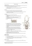
Digital clamp meter Operation Manual 3-1-6. Relative value measurement. Range Accuracy Resolution 3-1-7. Sampling rate:3times/sec. 400Ω ±(0.8%reading+5) 0.1Ω To avoid possible electric shock or personal injury, please read 3-1-8. Low battery display. the Operation Manual before use and follow all safety 3-1-9. Continuity test: If the resistance is instructions. buzzer sounds continuously. 1. General 3-1-10. Auto range or manual range. This meter is a portable digital clamp meter, which is used to 3-1-11. Auto power off. measure ACA, ACV,DCV, resistance, capacitance, temperature, 3-1-12. power consumption:Approx. 3Ma. frequency and other functions. It’s an excellent instrument for 3-1-13. Battery: 2pcs 1.5V battery (“AAA”7# battery. auto checking, repair, maintenance. It can be used in laboratory, 3-1-14. home, as well as large current measurement sites. humidity<70%RH. 2. Safety note 3-1-15. Size: 228mm*75mm*35mm (length*width*height). The meter meets the standards of IEC1010-1 (EN61010-1) 3-1-16. Weight: about 260g (including battery). pollution2, CAT.III600V and UL3111-1. Read the operation 3-1-17 . accessories: operation manual, test leads, temperature manual carefully before operation. probe, 2pcs AAA batteries ,gift box. 2-1. Safety Symbols 3-2.FEATURES Working 4kΩ <(50±10)Ω, the 1Ω 40kΩ 10Ω ±(0.8%reading+3) 400kΩ 100Ω 4MΩ 1kΩ 40MΩ environment: ±(1.2%reading+5) 10kΩ Overload protection: 250V DC /ACRMS. Warning: Please don’t input voltage value at this range. (0 ~ 40)℃, relative 3-2-7. Capacitance Range Accuracy resolution 4nF ±(5.0%rading+20) 1pF 40nF 10pF 400nF “ “ ”THE OPERATOR MUST REFER TO THE MANUAL, ”LOW BATTERY. “ VOLTAGE, “ ”EXISTS DANGEROUS ”DUAL INSULATION. 3-2-1.Accuracy: ± (a% × reading data + digits), environment temperature at (23±5) ℃, relative humidity<75%, One year 2-2. Notes 3-2-2. Temperature coefficient: 0.1* ted accuracy /1℃(<18℃ or 2-2-1. Read the operation manual carefully before operation, in >28℃). order to avoid endangering the personal safety and meter damage, 3-2-3. DC voltage Accuracy Resolution requirements. 400mV ±(1.0%reading+5) 0.1mV 40V 1mV 10mV ±(0.5%reading+5) Water is forbidden to leak into the meter cover inside. 400V 100mV 2-2-3. Do not operate the meter with the cover removed or the 600V 1V case open. 2-2-4. Do not input limit over-ranged. 2-2-5. Do not input voltage value at resistance, capacitance, Continuity, diode and temperature range. 2-2-6. The power switch should set to OFF after finishing measurement. 2-2-7. For storing a long time, remove the battery to avoid ±(5.0%reading+10) 100nF Warning: Please don’t input voltage value at this range. Accuracy Resolution 100Hz 0.1Hz 1kHz 0.1Hz 10kHz 1Hz ±(0.5%reading+5) 100kHz 10Hz 1MHz 100Hz 10MHz 1kHz 3-2-9. Temperature 3-2-4. AC voltage Range Accuracy Resolution 400mV ±(1.5%reading+5) 0.1mV 4V 1mV 40V 10mV ±(1.0%reading+5) Range Accuracy Resolution <400℃±(1.0%+5) (-40~750)℃ 1℃ ≥400℃±(1.5%+15) Sensor:K type banana probe (Ni-Cr - Ni-Si). Warning:Please don’t input voltage value at this range. 400V 100mV 600V 1V 3-2-10. Continuity test RMS, which will pose a shock hazard. will result in electric shock. 200uF Overload protection: 250V RMS. Overload protection: 600V DC /ACRMS 2-2-8. When working with voltages above 60V DC or 30V AC insulated conductor or bud bars, accidental conductor contact 10nF Input sensitive: >0.7V. Input impedance: approx. 10MΩ; battery leakage damage to internal components. 2-2-9. Please be especially careful when the meter clipped not 40uF Range Range test leads and disconnect meter from any circuits being measured. 1nF 3-2-8. Frequency we need to operate in accordance with the specification 4V 4uF Overload protection: 250V DC /ACRMS. guarantee since production date. 2-2-2. Before opening back cover to replace batteries, remove 100pF ±(3.5%reading+10) Range Display Test condition Input impedance: approx. 10MΩ; Forward DCA is Overload protection: 600V DC/AC RMS approx. 0.5mA, the Frequency response: (50~60) Hz at 600V range, other Forward voltage drop of range:(40~400)Hz. diode backward voltage of open circuit is 3. Features 3-2-5.AC current approx 1.5V 3-1. General Features 3-1-1. Displaying: LCD. 3-1-2. Max display: 4000 (3 3/4) digits automatic polarity display. Range Accuracy Resolution Buzzer makes a long 400A <800±(2.0%reading+5) 3-1-5. Hold: Data hold. sound while resistance is circuit is approx less than (50±10)Ω 0.5V. ≥800A±(4.0%reading+10) 1000A 1A 3-1-3. Max. jaw open:35mm. 3-1-4. Over-range display:“OL” displayed in the highest digit. Voltage of open 100mA Over load protection: 250V DC /ACRMS. Over load protection: 600A (input time can’t exceed 1 minute). Warning: Please don’t input voltage value at this range. Frequency response: (50~60)Hz 3-2-6. Resistance 4.Operation 4-1.Panel description (see Figure 1) ① 1) Jaw: A device to test the AC current, ② ③ ④ ⑨ ⑧ ⑤ ⑥ ⑦ which makes the current into voltage. The Measuring values hereafter will automatically deduct the 2) Connect the test leads to the test point, voltage and reference value, unless pressing the REL button again to exit polarity of the point which connect with red test leads will be reference value test function. display on LCD. 5) AUTO OFF: During measurement, if there is no operation 3)The default states is auto range, display AUTO symbol, with the buttons and switch, the unit will automatically turns press “range” switch to select off to save energy. To exit AUTO OFF function (hibernation choose 400mV, 4V, 40V, 400V, 1000V range, if the 2) Hand protection: A safe design to protect users from touching mode), please press HOLD button. Under AUTO OFF mode, amplitude is unknown, start from highest the dangerous area. press any button or turn the switch, the unit will get into 3) Clamp gunlock: Pressing the gunlock releases the clamp; “AUTO ON” (working mode). single conductor must get thought the clamp center range manual range , you can and decrease as necessary (see Figure.5) 4-4. Measurement of AC current NOTE: 1) Turn the function switch to ACA range 1) When only the most significant digit “OL” is voltage, resistance, capacitance, frequency, temperature, etc. 2) Open the clamp to clamp a conducting wire and read the displays, it means over-range, must set the range switch to a 5) LCD display. display directly. To get accurate display, it is suggested to put the higher range. 6) Function key: Chooses basic function. conducting wire in the center of the clamp. 2) The input voltage shall not exceed the voltage limit. 7) Voltage, Resistance, Frequency, Temperature” input COM. 3)The default states is auto range, display AUTO symbol, press Otherwise, the unit may be destroyed. 8) GND COM. “range” switch to select 3) Take extreme care to avoid the contact with high voltage 9) Carrying belt. 600A range, if the amplitude is unknown, start circuits when taking measurements in these circuits 4-2. Displaying symbols from 4-7. Measure of resistance releasing the gunlock closes the clamp. 4) Function choosing switch: Selects AC current, DC, AC highest range manual range , you can choose 400A, and decrease as necessary 1) Turn the function switch to Ω range, press SELECT to select resistance measuring mode. (see Figure.3) No. Symbols Meaning NOTE: 2) Then connect the red test lead into “VΩHz” input terminal 1) When only the most significant digit “OL” is displays, it and black test lead into “COM” terminal. means over-range, must set the range switch to a higher range. 3) Connect the test leads crossly with the resistor under tested. 1 Auto Auto Range 2) The input current shall not exceed the current limit. Otherwise, 3) If measuring the small resistance, should short-circuit at first, 2 - Negative reading the unit maybe destroyed. press “REL” switch, and then measuring the unknown resistance, Low battery indication 4-5.Measurement of AC voltage it actual resistance will be display on the LCD. 3 3)The default states is auto range, display AUTO symbol, press 4 AC AC mode 1) Turn the function switch to 5 DC DC mode to select AC measuring mode, then connect the red test lead into “range” switch to select “VΩHz” input terminal and black test lead into “COM” terminal. can choose 400Ω, 4kΩ, 40kΩ, 400kΩ, 2) Connect the test leads to the test point, voltage and polarity of 4MΩ, 40MΩ range, 6 Diode, Continuity test 7 REL Relative value symbol 8 M-H Maximum reading display 9 D-H,HOLD 10 mV-V 11 Ω/KΩ/MΩ Data hold Voltage unit: mV/ V Resistance unit: Ω/KΩ/MΩ 12 uA/mA/A Current unit: uA/mA/A 13 nF/uF Capacitance unit: nF/uF 14 Hz/kHz/MHz Frequency unit: Hz/kHz/MHz 15 ℃/℉ Temperature unit: ℃/℉ 4-3. Button functions and Auto off 1) SELECT: Under mull-function mode, press SELECT to choose related function. 2) RANGE: Press this button to select suitable range. Press it for more than 2 seconds to get back to AUTO mode. 3) HOLD: Press this button to hold the current measured value range. Press SELECT switch the point which connect with red test leads will be display on manual range , you (see Figure.6) LCD. NOTE: 3) The default states is auto range, display AUTO symbol, press 1) If the measured resistance is unsure beforehand, should set the “range” switch to select range switch to a higher range, then, switch to a proper range manual range , you can choose 400mV, 4V, 40V, 400V, 600V range, if the amplitude is unknown, start according to the displayed value. from highest range 2) If “OL” displays, it means over-range, the range switch should and NOTE: NOTE: be set to a higher range. When the resistance is over 1MΩ, the 1) The 400mV range only has the manual range, if you need to reading should take a few seconds to be stable. It is normal at use 400mV range, press “RANGE” key to select this range. high resistance measurement. 2) When only the most significant digit “OL” is displays, it 3. When input terminal is open circuit, “OL” displays. means over-range, must set the range switch to a higher range. 4. When measuring in-line resistance, be sure the power has been 3) The input voltage shall not exceed the voltage limit. turned off and all capacitors are fully released. Otherwise, the unit may be destroyed. 5. Do not input voltage at this range. 4) Take extreme care to avoid the contact with high voltage 4-8.Measurement of capacitance circuits when taking measurements in these circuits. 1)Turn the function switch to 4-6.Measurement of DC voltage SELECT to select resistance measuring mode. range, press on LCD. Press it again to exit the hold model. Note: after AUTO off, press the HOLD button to cancel the auto off function. 4) REL: Press this button to make the current displayed value as reference value, meanwhile the LCD displays as zero. 1) Turn the function switch to range. Then connect the 2)Connect the red test lead into “VΩHz” red test lead into “VΩHz” input terminal and black test lead input terminal and black test lead into into “COM” terminal. “COM” terminal. (see Figure.7) 3) If the LCD is not display zero, press REL to make display as black test lead into “COM” terminal. (see Figure.10) manufacturer. zero. 3) Press SELECT to select continuity The manufacture dose not take responsibilities for accidents and 4) Use the test leads (the read test lead as “+”)to connect the display the symbol harm caused by wrong operations by the users. capacitance into “COM” and“ VΩ” terminal correctly. The LCD 4) Connect the two test leads on the testing circuit with some The functions described in this manual shall not be considered as will display capacitance value. distance. If the buzzer rings, the testing resistance will be less the reasons to apply the unit to special usages. NOTE: than 50±10Ω. 1) Do not input voltage or current signal under the capacitance 5) Press SELECT to select diode test mode. The LCD will range. If there is display on LCD, press REL to make LCD test mode, the LCD will display the symbol display as zero so as to make sure of accurate measurement. 6) Forward measurement: Connect the red test lead on the testing 2) There is only auto measurement mode under capacitance diode’s positive polarity and black test lead on negative polarity, range. the LCD will display the approximated value of diode voltage 3) To protect the unit, make sure that the testing capacitances drop. completely discharged. 4) 7) Reverse measurement: Connect the red test lead on diode’s Display of 200uFrange is stable for more than 15 seconds. negative polarity and black test lead on positive polarity, the 4-9. Measurement of Frequency LCD will display “OL”. 1. Connect the red test lead into “VΩHz” input terminal and 8) A completer diode test includes forward and reverse tests. If black test lead into “COM” terminal. the testing results are not in compliance with the above, then 2. Turn the function switch to “Hz” range. diode is broken. 3 The range is auto-range. Connect the leads across to the signal NOTE: Do not input voltage under this range! under measured; the value will be displayed on LCD. 5. Maintenance NOTE: The unit is a precise instrument. Random changes to the circuit 1. There is only auto-range at this range. are not allowed. Users shall pay attention to the following: 2. When input is over 10V Ac RMS, reading is possible, but maybe over-range. 1) If the LCD display the symbol , please replace the battery. 3. It’s better to use shield cable when measuring small signals in noisy place. 2) Before replacing the battery, move the test lead from the testing objects and turn off the power. Release the screws on 4. Be careful when measuring high voltage. 5. Do not input voltage over 250V DC/ACRMS. the battery cover and replace the battery. 3) Do not expose the unit under direct sunshine, high 4-10. Measurement of temperature temperature, flammable & explosive environment nor strong Turn the function switch to TEMP range. Then connect the magnetic environment. negative terminal (black) of thermocouple sensor to the “COM” 4) Keep away from humidity and dust. Do not fall it. terminal and the positive (red) to the “VΩHz” terminal. Put the 5) Use cloth with cleanser rather than corrosive solvents to testing terminal of thermocouple sensor on or into wipe and clean the unit regularly. the testing object, then read the temperature 6. Troubleshooting (℃) from the LCD display. (see Figure.9) If the unit dose not work normally, please refer to the following NOTE: solutions. If the problems still cannot be solved, please refer to 1) During test, put the unit away from high repairing service center or contact the local dealers. temperature, and use the testing terminal of thermocouple sensor Problems within testing limits. Connect the unit to 2) To make sure of accurate testing results, do no replace the thermocouple sensor randomly. power. Do display 3) Do not input voltage under this range. “normal temp. 1) Turn the function switch to press Replace battery appears 4-11. Measure of Continuity and diode SELECT to Turn on the ON/FF switch. 4) When the input terminal is in open circuit, will display the range, Solutions Obvious display Replace battery Replace battery error select The specifications are subject to changes without notice. continuity test mode. The operation manual is considered as correct. Should the users 2) Connect the red test lead into “VΩHz” input terminal and find any mistakes or omission, please kindly contact the 706B-V1.0