1
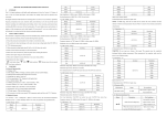
1-7.Storage environment: Temperature (-10℃ to 50℃), humidity<80%RH. OPERATION MANUAL The meter is a high performance, high accuracy, 3 3/4-digit, 32mm digit high by LCD displaying meter. The function includes DCV, ACV, DCA, ACA, 4000uA 1μA 40mA 10μA 400mA 100μA 4A 1mA 1-8.Power: 2pcs 1.5V AAA 7# battery. 1-9.Dimension: 185(L)X93(W)X35(H)mm. 1-10Weight: Approx. 290g(including battery). resistance ,capacitance, frequency, temperature,duty cycle measurement, triode, 1-11.Accessories: manual, gift box ,holster ,TP01 temperature probe, test leads and diode and continuity test. Also with the function of unit signal displaying ,relative 2pcs 1.5V battery. value measuring ,auto range/ manual range switch ,auto power off and warning 2. Technical 20A function etc. ±(2.0%+5) 10mA 2.1 Accuracy: ±(a% × reading + digits) at 23±5℃,<75%RH. SAFETY NOTES Max. measuring volt drop: 400mV under mA range, 200mV under A 2.2 DCV The meter meets with IEC1010standard. Read the notes before operating. ①Before measuring, check the test leads carefully. ②Do not input a value over allowable limited when measuring to avoid electric shock meter damage. Range Accuracy range. Resolution 400mV 0.1mV 4V 1 mV Max. input current: 20A(less than 15sec.) Overload protection: 0.5A/250V fuse, 13A/250V fuse. ±(0.5%+4d) ③Be careful when measuring voltage over DCV60V, ACV40V. ④To select correct function. ⑤The test leads should be taken away from the testing point when changing 40V 10 mV 400V 100 mV 2.5 ACA Range 1000V ±(1.0%+4d) 1V Resolution 400uA 0.1μA 4000uA 1μA Input impedance: 400mv range>40MΩ,other range is 10MΩ. function. ⑥Never take measurement when the test leads are in current terminal. Overload protection: 1000V DC or 700V AC peak value Range ⑧Safety symbols “ “ dangerous voltage 400mV “ “ GND 4V “ “ dual insulation 40V “ “ refer to the operation manual 400V “ “ low battery 750V Accuracy Resolution ±(1.5%+6d) 400mA 100μA 4A 1mA 1 mV ±(0.8%+6d) 10 mV 20A 100 mV ±(1.0%+6) 10μA 0.1mV ±(2.0%+10) 10mA Max. measuring volt drop: 400mV under mA range, 200mV under A 1V range. Input impedance: 400mv range>40MΩ,other range is 10MΩ. Max. input current: 20A(less than 15sec.) SPECIFICATION Overload protection: 1000V DC or 700V AC peak value 1. General Frequency response: 750V range: 40~100Hz, other range: 40~400Hz 1-1,Display: 3 3/4digit LCD with a max readings of 3999, Automatic ±(1.5%+5) 40mA 2.3 ACV ⑦Do not try to modify the circuit. Overload protection: 0.5A/250V fuse, 13A/250V fuse. Displaying: sinewave RMS(average value response) Frequency response: 40~100Hz under 10A range, 40~400Hz at other range. negative polarity indication., 2.6 RESISTANCE 1-2.Measuring method: Dual-slop integrating A/D converter system. 2.4 DCA 1-3.Sampling rate: Approx. 3times/second. Range Range Accuracy 400uA ”is display. 1-6.Operating environment : Temperature (0℃ to 40℃), humidity<80%RH. Accuracy Resolution Resolution 1-4 Over range indication: “ OL” display. 1-5.Low battery: The “ Accuracy ±(1.0%+5) 400Ω ±(0.8%+5) 0.1Ω 4kΩ ±(0.8%+1) 1Ω 0.1μA 40kΩ 10Ω 400kΩ 100Ω 30MHz 1kHz 2-2.Hz/DUTY key:when measuring the AC voltage or AC current, it can INPUT SENSOR:0.7V。 switch frequency/duty cycle/voltage(currect),when measuring the Overload protection: 250V DC/AC peak value 4MΩ sleep or lock states, press this key, the meter will be actived. frequency, it can switch frequency/duty cycle(1-99%). 1kΩ 2-3.REL key: press this key, clear the reading to Zero, enter relative 40MΩ ±(1.2%+5) 10kΩ 2-9. hFE value measuring. Open circuit voltage: 400mV. Overload protection: 250V DC/AC peak value Range Accuracy Test condition hFE NPN or 0~1000 Current is 15uA, Vce is PNP NOTE: approx. 4.5V 2-4:HOLD key: press the key, the present measuring value is held on LCD and display“HOLD”; press it again will exit the function and “HOLD” 2.7 CAPACITANCE Range Accuracy 4nF Resolution ±(2.5%+6) 1pF 40nF 10pF 400nF 100pF Range 40μF 10nF ±(5.0%+8) Resolution Diode forward volt Forward DCV is approx. If the resistance of the 1nF 100nF Overload protection: 250V DC/AC peak value WARNING: do not input any voltage at this range! When measuring, the capacitor should be completely released and the power must be turned off. 10Hz 0.5mA, reversed voltage is approx. 1.5V 4.Temperature jack. Open circuit voltage: 0.5V 5.Voltage,Current,Resistance,Frequency,GND jack 6.Battery Case. less than (70±10)Ω, See the photo buzzer sounds. 4-2. DCV measurement Overload protection: 250V DC/AC peak value 1 Insert the black lead to “COM” socket and the red one to “ VΩHz” WARNING: do not input any voltage at this range. socket; 2.11 TEMP. 2 Set the function switch to “V” range, press DC/AC key to select DC Range Accuracy Resolution Resolution ±(0.5%+4) 0.001Hz -40℃-1000℃ 1℃ ≥400℃±(1.5%+15) Thermocouple: K type WARNING: do not input any voltage at 100Hz 0.01Hz 1000Hz 0.1Hz 10kHz 1Hz this range. measuring mode. 3.the default states is auto range, display”AUTO” symbol,press “range” <400℃ ±(0.8%+4) Accuracy 2-6.DC/AC key,select DC/AC mode. 3.Knobe:change measuring function and range. two tested points is 2.8 FREQUENCY Range 2-5.Range key: select auto range or manual range. Accuracy drop ±(3.5%+8) 4μF 200μF disappear. 2.10 DIODE AND CONTINUITY TEST key to select manual range , you can choose 400mV、4V、40V、400V、 1000V range. 4.connect the test leads to the test point ,voltage and polarity of the point which connect with red test leads will be display on LCD. NOTE: OPERATION 1. to a higher range. 4-1. panel description 100kHz 10Hz 1MHz 100Hz 1. LCD displaying 2. Function keys: 2-1.RST key: when the meter under If “OL” displays, it means over-range, should set the range knob 2. The tested voltage can not be over 1000V DC; when changing function and range, the leads must be away from the testing point. 3. Be careful when measuring high voltage. even damage the meter. 4.When measuring in-line resistance, be sure the power has been turned off and all capacitors are fully released. 4-3. ACV measurement 4-5. ACA measurement 5.Do not input voltage at this range. 1. Insert the black lead to “COM” socket and the red one to “ VΩHz” socket. 1 Insert the black lead to “COM” socket and the red one to “mA” or “20A” socket. 2. Set the function switch to “V” range, press DC/AC key to select AC measuring 4-7. Capacitance measurement 2.Set the function switch to “A” range, press DC/AC key to select AC working mode 1 Set the function switch to “ ” range mode ,connect the test leads across to the circuit under tested, the current value and 2. Insert the black lead to “COM” socket and the red one to “ VΩHz” 3.the default states is auto range, display”AUTO” symbol,press “range” key to polarity of the point which red lead connect will display on LCD. socket. select manual range , you can choose 400mV、4V、40V、400V、750V range. 4.connect the test leads to the test point ,voltage and polarity of the point which 1.If the measured current is unsure beforehand, should set the range knob to a higher range, connect with red test leads will be display on LCD. then, switch to a proper range according to the displayed value. 3.if the LCD isn’t display zero ,press “REL” key to clear zero. 4. Insert the capacitor to “Cx” socket according to the polarity, the value will display on LCD. NOTE: 2.If “OL” displays, it means over-range, should set the range knob to a higher range. 1. the 400mV range only has the manual range,if you need to use 400mV NOTE: 3.When tested current ≥10A under 20A range ,buzzer will be sound. range,press “RANGE” key to select this range. 2.If “OL” displays, it means over-range, should set the range knob to a higher 1. 4.Max. input current is 400mA or 20A(subject to where red lead insert) ,excessive current range. will blow the fuse. Be careful when measuring 20A due to un-fused. Continuously 3.The tested voltage can not be over 750V AC; when changing function and measuring large current may heat the circuit, affect the accuracy, even damage the range, the leads must be away from the testing point. 4.Be careful when measuring high voltage. meter. 4-4. DCA measurement Don’t input voltage and current signal in the “VΩHz” jack when measuring the capacitor. 2. Be sure to press “REL” to clear zero before measuring. 3. Capacitance range only have auto range working mode. 4. Release the capacitors completely to avoid damaging the meter 5. 200uF range input reading steady large than 15 Sec,. 6. Unit: 1uF=1000nF 1nF=1000pF 4-6. Resistance measurement 1 Insert the black lead to “COM” socket and the red one to “mA” or “20A” socket. 4-8. Frequency measurement 1. Insert the black lead to “COM” socket and the red one to “ VΩHz” socket. 2 Set the function switch to “A” range, press DC/AC key to select DC working 1. Insert the black leads to “COM” socket and the red one to “VΩHz” 2. Set the function switch to “Ω” range, if the resistance under measured f unknown, mode,connect the test leads across to the circuit under tested, the current value and socket. should set to a higher range. polarity of the point which red lead connect will display on LCD. 2. Set the range switch to “Hz” range. 3.press “Range ” key to select auto range or manual range mode. 3 The range is auto-range. Connect the leads across to the signal under NOTE: 4.if measuring the small resistance, should short-circuit at first, press “REL” key,and then 1.If the measured current is unsure beforehand, should set the range knob to a measured, the value will be displayed on LCD. measuring the unknown resistane, it actual resistance will be display on the LCD, NOTE: higher range, then, switch to a proper range according to the displayed value. 2.If “OL” displays, it means over-range, should set the range knob to a higher NOTE: 1. range. If the measured resistance is unsure beforehand, should set the range knob to a 1. There is only auto-range at this range. 2. When input is over 10V Ac rms, reading is possible, but maybe over-range. higher range, then, switch to a proper range according to the displayed value. 3.When tested current ≥10A under 20A range ,buzzer will be sound. 3. 2. If “OL” displays, it means over-range, the range knob should be set to a higher place. 4.Max. input current is 400mA or 20A(subject to where red lead insert) ,excessive range.When the resistance is over 1MΩ, the reading should take a few seconds to be current will blow the fuse. Be careful when measuring 20A due to un-fused. stable. It is normal at high resistance measurement. Continuously measuring large current may heat the circuit, affect the accuracy, 3.When input terminal is open circuit, “OL” displays. It’s better to use shield cable when measuring small signals in noisy 4. Be careful when measuring high voltage. 5. Do not input voltage over 250V DC/AC peak value. 4-9. hFE measurement 1. Set the function switch to hFE range. 10. Replace the fuse with same type and rating as the replacements. 2 .Define the transistor is NPN or PNP type, insert the emitter, base and collector 4-13 Auto power off separately to the correct hole, the approx. value will be displayed on LCD. 1.When operating after 15 minutes, the meter will be auto power off and into sleep mode; 4-10. Diode and continuity Test Press “POWER AUTO OFF” key twice can turn the power on 1. Insert the black leads to “COM” socket and the red one to “VΩHz” socket( the 2.press “DC/AC” key before turn on, it can cancel auto power off function. 六. If the meter does not work properly, check the meter as following: CONDITIONS Power is off polarity of the red one is “+”). NO DISPLAYING 2. Set the FUNCTION switch to “ “ DC/AC WAY TO SOLVE ” position. Press ”key to select diode measuring. HOLD key MAINTENANCE Replace battery Do not try to modify the inner circuit. symbol displays 3. Forward measurement: connect the red test leads to the “+” polarity of the diode NOTE: under tested and the black one to “-“, the approx. forward voltage of this diode will 1. Do not input a voltage over 1000V DC/AC peak value. be displayed on LCD. 2. Do not measure voltage at current range, resistance range, diode and buzzer range. 4 Backward measurement: connect the red test lead to the “-“ of the diode and the 3. Do not use the meter if the battery is not replaced well or the battery case is not fixed. black one to “+”, and LCD will displayed OL. The completely measurement 4. Before replacing battery or fuse, release the test leads from the test point and turn power includes forward and backward measurement, if the result can not meet with the off. above, it means the diode is workless. 5.Keep the multimember dry. Keep the multi-meter away from dust and dirt 5.Diode test include forward measurement and backward measurement, if the result 6.Use and store the multi-meter only in normal temperature environments. Temperature is different with above, the diode is bad. extremes can shorten the life of electronic devices, damage batteries, and distort or melt 6.press “DC/AC” key to select continuity test. plastic part. 7.Continuity test: the buzzer sounds when the resistance under measured is less 7.Handle the multiyear gently and carefully. Dropping it can damage the circuit boards and than (70+10)Ω. case and can cause the multi-meter to work improperly although the holster can provide Note: enough protection. Do not input voltage at this range. 8.Wipe the multi-meter with a damp cloth occasionally to keep it looking new. Do not use 2. Turn off the power and release all capacitors when testing in line. harsh chemicals, cleaning solvents, or strong detergents to clean the multi-meter. 9. Take out off the battery if do not use for a long time. When LCD displays “ battery should be replaced. 2.Insert the cold point of thermocouple too “Temp” socket and the working point to 9.1 ref.pic.2 to take the place wanted to take temperature, the value will be displayed on LCD. out the holster. NOTE: 9.2 1. When the input terminal is in open circuit, will display the “ normal temp.” screw on the bottom 2. Do not change the thermocouple, or, the accuracy can not be secured. case 3. Do not input voltage at this range. bottom case. Remove and lift the the 9.3 Remove the spent 4-12.DATA HOLD battery and replace it Press “ HOLD” key once, the current data will be hold on LCD, press it again, data with a battery of the is canceled. same type. The content of this manual is regarded as correct, error We hereby will not be responsible for the accident and damage caused by improper operation. 1. 1. Set the function switch to “℃” range. The specifications are subject to change without notice. or omits Pls. contact with factory. 4-11. Temperature measurement Replace battery BIG ERROR Replace battery ”, the The function stated for this User Manual cannot be the reason of special usage.