1
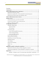
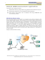
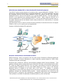
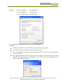
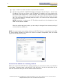
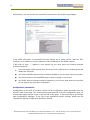
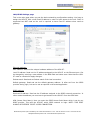
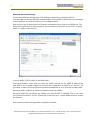
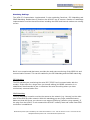
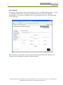
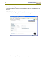
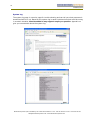
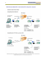
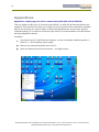
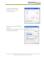
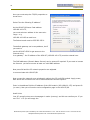
1
UCM-97 Industrial TCP/IP
Communicator with GPRS
(Also valid for UCM-99)
User and Configuration Manual
V. 2.01 / Nov 2010 / Doc 40153
Brodersen Systems A/S ● Islevdalvej 187 ● DK-2610 Roedovre ● Tel: +45 45 35 26 27 ● Fax: +45 45 35 26 29
[email protected] ● www.brodersensystems.com
2
Contents
Introduction ..................................................................................................... 4
UCM-97 GPRS Communicator applications ....................................................... 5
GPRS Wireless Ethernet routing ........................................................................ 5
GPRS Wireless ModbusTCP to Serial ModbusRTU Enabled Equipment ..................... 6
GPRS Wireless Communication with Brodersen RTUs ........................................... 6
UCM-97 GPRS Communicator features ............................................................. 7
Getting started ................................................................................................. 8
Connect directly from your PC to the UCM-97 ..................................................... 8
Connect to the UCM-97 via an existing network ................................................ 10
Setting up UCM-97 for GPRS ........................................................................... 11
Configuration parameters .............................................................................. 12
LAN/GPRS Settings page ................................................................................ 13
Ethernet settings: .................................................................................... 13
GPRS settings: ......................................................................................... 13
Port Settings page ......................................................................................... 14
Serial to Ethernet/GPRS functionality .......................................................... 14
Serial Tunnelling Settings .......................................................................... 14
Serial Port(COM2) settings ........................................................................ 15
Reverse Gateway Settings .............................................................................. 16
Wireless Ethernet Settings.............................................................................. 17
DynDNS.org / Dynamic DNS settings ............................................................... 18
Watchdog Settings ........................................................................................ 19
Time Settings ............................................................................................... 20
Access Control Settings .................................................................................. 21
System Log .................................................................................................. 22
Service ........................................................................................................ 23
Application specific configuration guidelines ................................................. 24
GPRS Wireless Ethernet routing of data configuration examples .......................... 24
GPRS Wireless ModbusTCP to Serial ModbusRTU configuration examples .............. 25
Appendixes .................................................................................................... 26
Appendix 1: Setting up your PC to communicate with UCM-97 and UCM-99 ..... 26
Brodersen Systems A/S ● Islevdalvej 187 ● DK-2610 Roedovre ● Tel: +45 45 35 26 27 ● Fax: +45 45 35 26 29
[email protected] ● www.brodersensystems.com
3
Appendix 2 Assigning an IP address to the UCM-97 module using AutoIP: ....... 29
Appendix 3 Firmware Upload Guide ............................................................ 30
Appendix 4 Notes for users of older firmware releases .................................. 31
Appendix 5 Preliminary Data on Event Reporting feature ............................... 32
Brodersen Systems A/S ● Islevdalvej 187 ● DK-2610 Roedovre ● Tel: +45 45 35 26 27 ● Fax: +45 45 35 26 29
[email protected] ● www.brodersensystems.com
4
1 Introduction
The UCM-97 GPRS Communicator provides you with GPRS wireless online networking
communication with our devices. The UCM-97 GPRS Communicator is designed to handle the
GPRS communication and have integrated facilities for industrial use like extended watchdog
functions, handling of dynamic GPRS IP addresses and communication routing. The setup and
configuration facilities are simplified in order to provide you with easy handling of all the
relative complicated networking configurations parameters required when setting up TCP/IP
based communication applications. It is however recommended having basic knowledge about
networking and TCP/IP.
Your device does not have to support TCP/IP or PPP to work with the UCM-97. We can also
provide tunnel facilities to pass any proprietary or open serial protocols to anywhere on your
network.
Brodersen Systems A/S ● Islevdalvej 187 ● DK-2610 Roedovre ● Tel: +45 45 35 26 27 ● Fax: +45 45 35 26 29
[email protected] ● www.brodersensystems.com
5
UCM-97 GPRS Communicator applications
The UCM-97 offers 3 different functions :
GPRS Wireless Ethernet routing of data to any equipment with an Ethernet coms port.
GPRS Wireless ModbusTCP to Serial ModbusRTU enabled equipment.
GPRS Wireless Communication with all Brodersen RTUs using IOTOOL32Pro and
ReverseGateway software.
GPRS Wireless Ethernet routing
One of the special features of the UCM-97 is its integrated routing function designed to offer
wireless Ethernet data exchange. GPRS networks do not normally support routing facilities,
but the UCM-97 GPRS Communicator can be configured to route communications to a local
network connected to the Ethernet interface of the UCM-97. A Network Address Translation
(NAT) routing table is set up in the UCM-97 which will link the communication to the right
recipient in the network. To cope with firewall restrictions e.g. for FTP (File Transfer
Protocol), the UCM-97 features a special, automatic FTP Natting Function. When using the
UCM-97 GPRS Communicator for wireless Ethernet routing, it can be commissioned to operate
either on the public Internet with its own domain name (www.yourdevice) or, alternatively, in
a private network.
Example of Wireless Ethernet routing
Brodersen Systems A/S ● Islevdalvej 187 ● DK-2610 Roedovre ● Tel: +45 45 35 26 27 ● Fax: +45 45 35 26 29
[email protected] ● www.brodersensystems.com
6
GPRS Wireless ModbusTCP to Serial ModbusRTU Enabled Equipment
The UCM-97 gives wireless access to any device with a serial ModbusRTU interface. This is
achieved by configuring the UCM-97 to Wireless ModbusTCP. The serial ModbusRTU will thus
be converted into the TCP/IP based ModbusTCP and will respond like any other standard
ModbusTCP Server node on the Internet or on a private GPRS Intranet. This also allows the
UCM-97 to be accessed from multiple ModbusTCP clients. When using the UCM-97 as a
Wireless ModbusTCP to Serial ModbusRTU device, it can be commissioned to operate either on
the public Internet with its own domain name (www.yourdevice) or, alternatively, in a private
network environment.
The UCM-97can even be used to provide tunnelling facilities for devices which do not support
TCP/IP or PPP, e.g. for remote com port applications.
Example of Wireless ModbusTCP application
Wireless Communication with Brodersen RTUs
GPRS technology, used in conjunction with the wide range of Brodersen RTUs and Brodersen
drivers, presents a wireless alternative to earlier telemetry systems based on PSTN, GSM,
leased line and radio technology.
Brodersen also produces a network communication gateway called ‟Reverse Gateway‟. This
gateway software allows remote data from a Brodersen RTU to be communicated by the UCM97 using any GPRS enabled SIM card. This is a highly cost-effective concept for applications
involving global installations, as only local GPRS charges will apply, even if the ‟Reverse
Gateway‟ server is located on the other side of the world.
In addition, it operates
independently of any third party internet service as the user controls the communication and
gateways through any standard GPRS provider. Typical applications are monitoring and
alarming used in connection with asset/facility management and supply chain management.
This operates on all GPRS IP addresses; fixed and dynamic, public and private.
Brodersen Systems A/S ● Islevdalvej 187 ● DK-2610 Roedovre ● Tel: +45 45 35 26 27 ● Fax: +45 45 35 26 29
[email protected] ● www.brodersensystems.com
7
Example of application with UCM-97 communication with Brodersen System software and
hardware
UCM-97 GPRS Communicator features
The UCM-97 GPRS Communicator in the basic version offers:
GPRS Class 10.
Extended watchdog function monitoring the GPRS on-line connection and serial line
communication.
Built-in WebServer used for configuring the device with a standard browser like MS
Internet Explorer.
DynamicDNS implementation which allows you to use standard GPRS SIM cards with
dynamic assigned public IP addresses. In other words assign your own domain name
to your device.
Software enhancements giving you real wireless Ethernet like:
Routing facilities to remote small networks of intelligent controllers, RTUs etc.
Special FTP NAT functions that handle routing of FTP through GPRS networks
without getting blocked by firewalls in GPRS Networks.
Brodersen Systems A/S ● Islevdalvej 187 ● DK-2610 Roedovre ● Tel: +45 45 35 26 27 ● Fax: +45 45 35 26 29
[email protected] ● www.brodersensystems.com
8
Conversion options from simple serial communication to Ethernet based network
communication – like:
ModbusRTU to ModbusTCP conversion.
Serial tunnelling of serial data in IP frames on TCP ports of your choice.
Interfaces:
Ethernet 10BASE-T.
RS232 V24 or RS485.
FME GPRS/GSM connector for external antenna.
SIM card holder.
12-48VDC power supply input
Industrial mounting on 35mm DIN rail.
Full remote configuration, remote service and remote software update of the module.
Getting started
IMPORTANT
It will be an advantage to have a basic knowledge of TCP/IP and Ethernet networking before
you start using the UCM-97.
The UCM-97 is assigned an IP address and this can be found on the back of the module. You
will also find the unique MAC address of the unit.
Configuration of the module is done in the module WebServer homepages. You therefore need
to connect the module to a PC with a browser using the Ethernet interface.
There are basically 2 ways of connecting the UCM-97 GPRS Communicator;
Directly from your PC to the UCM-97.
Via an existing network in your workshop or office.
Connect directly from your PC to the UCM-97
Connecting directly from your PC is the most common way of connecting to the UCM-97. This
because the UCM-97 has been pre-assigned a factory default IP address (printed on the back
of the module).
NOTE: When connecting directly to your PC network adapter, be sure to use a crossover
Ethernet patch cable. The procedure is as follows:
In the properties dialog page (if you are running MS Windows) of your Network – Ethernet –
TCP/IP configuration you should assign your PC a valid IP address in the same subnet as
written on the UCM-97 module.
Brodersen Systems A/S ● Islevdalvej 187 ● DK-2610 Roedovre ● Tel: +45 45 35 26 27 ● Fax: +45 45 35 26 29
[email protected] ● www.brodersensystems.com
9
Example:
UCM-97 IP address:
192.168.100.175
Your PC IP address:
192.168.100.1
Your PC Subnet mask:
255.255.255.0
A more detailed guide to set-up your PC is given in appendix 1.
Procedure:
Connect the UCM-97 to your PC Ethernet interface and apply power.
After approximately 30 seconds the module has booted.
From a command promt type: “ping 192.168.100.175”. Be sure you have response
from the UCM-97.
Use a standard Web browser to open the network page: http://192.168.100.175. The
authentication login box will be displayed. If not be sure you have disabled use of
proxy in your browser settings.
Brodersen Systems A/S ● Islevdalvej 187 ● DK-2610 Roedovre ● Tel: +45 45 35 26 27 ● Fax: +45 45 35 26 29
[email protected] ● www.brodersensystems.com
10
Type in “admin” as both username and password to continue.
Now the main UCM-97 LAN/GPRS webpage will appear. See the figure 1. In the "Local
IP address" field you can enter a new IP address. In addition you must always enter
the Subnet mask despite this is NOT changed. After entering new parameters press
the “save” button. Finally, you must click the “boot” button (the boot button will show
up if you have made any changes) and the UCM-97 will reboot and is configured with
the selected IP address.
NOTE: Remember to change your PC IP address according to the changes you have
made on the UCM-97 module.
After the module has been booted, you are ready to change all the necessary settings f
or the serial lines, GPRS, etc.
NOTE: You must expect some delays whilst your PC TCP/IP driver is connecting to your UCM97. After making changes, the driver will search for network components, and you should
expect this to take some minutes.
Connect to the UCM-97 via an existing network
Before you connect the UCM-97 to an existing network you most be sure that your network is
in the same IP subnet range as the UCM-97 (192.168.100.x). As this is most often not the
case we recommend that you use the method mentioned above.
Brodersen Systems A/S ● Islevdalvej 187 ● DK-2610 Roedovre ● Tel: +45 45 35 26 27 ● Fax: +45 45 35 26 29
[email protected] ● www.brodersensystems.com
11
However if you do not have a crossover patch cable or for some reason can‟t establish
communication to the UCM-97 module it is possible to assign an IP address to the module by
using what is called AutoIP. Normally you don‟t need to enter this procedure but if please look
at appendix A.
Setting up UCM-97 for GPRS
The UCM-97 needs the following settings to be entered on the LAN/GPRS page (figure 1) to
work with GPRS:
APN: Access Point Name (must be entered in “….”).
Username: As used when you connect to an external server using dial-in networking.
Password: As used when you connect to an external server using dial-in networking.
Note that username and password are case sensitive. If no username and password are
defined for your GPRS account, leave the fields blank.
After entering the settings, press SAVE and REBOOT. Now the UCM-97 will reboot and try to
connect to the GPRS network.
Disconnect the power and place your GPRS-enabled SIM card in the SIM card slot. See the
figure of direction of the SIM card below. Press gently the SIM card down till you feel a small
“click” and the SIM card is fixed. (The SIM card is removed again by pressing it down till it is
released). Finally fit the antenna and connect the power again.
At power up the UCM-97 Communicator will attempt to connect to the GPRS network. You will
in the „Received IP address‟ field on the main page (LAN/GPRS) see the IP address assigned
the UCM-97 on the GPRS network.
If you get no assigned IP address after reboot, try to refresh the webpages with F5. If no IP
address still appear, check the APN, username, password and even check that the SIM card
used is GPRS enabled.
Brodersen Systems A/S ● Islevdalvej 187 ● DK-2610 Roedovre ● Tel: +45 45 35 26 27 ● Fax: +45 45 35 26 29
[email protected] ● www.brodersensystems.com
12
Alternatively, you can monitor the connection procedure on the System log webpage.
If the GPRS connection is successful the trace should be as shown above. Note the PPP:
interface_up IP address is also the address of the IP address for the GPRS network.
If NO lines of “ppp:…..” appears in the system log you must trace the following possible
problems/solutions;
Your SIM card is either blocked by a PIN code. Put the SIM card on a mobile phone and
disable the PIN code.
Your SIM card GPRS account has not been activated by you provider. Call the provider.
The APN entered on the LAN/GPRS page is either missing or not correct.
Your GPRS account username and/or password is not correct. Note that some provider
do not require any username or password.
Configuration parameters
Configuration of the UCM-97 module is done via the configuration pages accessible from the
UCM-97 main home page. The sections below each describe one such configuration page. To
access these pages use the menu in the left side of the page. In the following we go through
each configuration webpage. If you like to get application specific settings, please use the
“Application Specific Configuration Guideline” section.
Brodersen Systems A/S ● Islevdalvej 187 ● DK-2610 Roedovre ● Tel: +45 45 35 26 27 ● Fax: +45 45 35 26 29
[email protected] ● www.brodersensystems.com
13
LAN/GPRS Settings page
This is the main page where you set the basic networking configurations setting. You have to
assign the UCM-97 with a local fixed IP address in order to have access to the unit. DHCP is
supported but NOT used as the unit is required to have fixed IP address when used as
gateway.
Ethernet settings:
MAC Address: Read out the unique hardware address of the UCM-97.
Local IP address: Read out the IP address assigned to the UCM-97 on the Ethernet port. Can
be changed by entering a new address in the NEW field and select save. Note that the UCM97 must be rebooted to apply changes.
Subnet mask: Read and set Subnet mask of the local connection.
Default gateway: Read and set the default gateway address. Is often set from the GPRS
provider during login, but can be set as required in the actual application.
GPRS settings:
Received IP address: Read out the IP address assigned to the GPRS network connection. In
other words the address you must use to get access to the UCM-97 from the GPRS side.
APN (Access Point Name): Here you enter the GPRS Access Point Name which is set by you
GPRS provider. This tells the UCM-97 which GPRS network to login. NOTE: THIS MUST
ALWAYS BE ENTERED TO GET A GPRS CONNECTION.
Brodersen Systems A/S ● Islevdalvej 187 ● DK-2610 Roedovre ● Tel: +45 45 35 26 27 ● Fax: +45 45 35 26 29
[email protected] ● www.brodersensystems.com
14
PPP Login Username and Password: Often your GPRS account is protected by a username and
a password. Like when you have an ISP account which normally also is protected by
username and password. If your GPRS account require username and password, it shall be
entered here.
Port Settings page
The Port settings page allows you to configure the serial port on the UCM-97 and also to
select what type of communication is used on the serial port. The serial port (COM2) on the
UCM-97 is always used for data communication form or to the network interfaces (GPRS and
Ethernet). The network ports are considered as parallel ports. All traffic, which is available on
the Ethernet port, is also available on the GPRS “port”.
Serial to Ethernet/GPRS functionality
You can here select if you want the data on the serial port put into a TCP/IP serial tunnel or if
you are using the built-in ModbusRTU-to-ModbusTCP converter.
Serial Tunnelling Settings
TCP port: Define the TCP port used for serial data. If ModbusTCP is used the port address is
standard defined as 502.
Brodersen Systems A/S ● Islevdalvej 187 ● DK-2610 Roedovre ● Tel: +45 45 35 26 27 ● Fax: +45 45 35 26 29
[email protected] ● www.brodersensystems.com
15
Down Timeout: If the serial socket connection is initialised from the UCM-97, the Down
timeout define the time to the UCM-97 to connect to a Server – for example the
ReverseGateway Server.
NOTE: If you enable the ReverseGateway function the Down timeout must set to s higher
value higher than 0 – if not, the automatic login to a ReverseGateway Server will NEVER
start.
When the UCM-97 is started with the ReverseGateway function the timer will start. After the
time times out the UCM-97 will make a login procedure. After have logged in to the server
and has a connection the timer will stop. It will not start again before the connection is down
or lost again.
Idle Timeout: If you have a port server connection and there has been no communication for
a specified time (timeout time) the connection will be closed down. When the connection is
closed down the timer will stop and it will not start again until a new port connection is
established.
Serial Port(COM2) settings
In general you here set the serial data format parameters for the serial port on the UCM-97.
If you are using the UCM-97 version with RS485 on COM2, you must select RS485 in the Flow
Control settings.
The serial buffer settings are mainly used when using serial tunnelling. If ModbusTCP is used,
predefined default settings are used. Buffer setting/adjusting details:
Tx Buffer:
port.
Define the Byte size of the buffer of transmitted data via TCP/IP to the serial
Rx Buffer:
Define the Byte size of the buffer of received data from the serial port to be sent
via TCP/IP.
Rx Bundle: Define the number of Bytes from the serial port to await before packing and
sending via TCP/IP.
If a serial data protocol frame is greater than the RX bundle setting, the number of Bytes
defined in the RX bundle is send when received – which means that the data protocol frame is
parted in 2 or more IP packages when transmitted via TCP/IP.
If the Rx Bundle is set to higher value that the number of Bytes in the serial data protocol
frame, the serial data will await approx. 10ms in the buffer after the last received Byte and
then be transmitted via the TCP/IP port.
In general it gives you two options when tunnelling serial data.
Option 1
Set RX Bundle low = Pass data as fast as possible without any preference for having complete
serial protocol data frames in each IP package.
Brodersen Systems A/S ● Islevdalvej 187 ● DK-2610 Roedovre ● Tel: +45 45 35 26 27 ● Fax: +45 45 35 26 29
[email protected] ● www.brodersensystems.com
16
Option 2
Set Rx Bundle > max. protocol frame size = Send every serial protocol data frame in one IP
package. Remember to calculate with about 10ms timeout after last character before
transmitting via TCP/IP.
An example could be with the ModbusRTU serial protocol. Then it is recommended to adjust
the RX Bundle value to 512 bytes.
Note that on GPRS communication links you must have a long timeout on your serial master
driver as the turn-around time GPRS applications in extreme load situations could be up to
20s. If no timeout the driver will timeout before getting the requested reply from the slave.
Reverse Gateway Settings
When you are using the UCM-97 Communicator in an application with Brodersen Reverse
Gateway Server and Brodersen hardware, you can enable the Reverse Gateway automatic
login on this page. When enabled the UCM-97 will automatically login to the
ReverseGatewayServer at power-up. The UCM-97 will then appear in the Gateway monitor list
of attached RTUs with the UCM-97 specific MAC address.
NOTE: The time out settings found on the port setting page must be set to :
Down timeout = 30s
Idce timeout = 45s
If Down timeout is set to 0, the ReverseGateway function will not be initiated at all!
See the Reverse Gateway Server manual for more details. NOTE that you MUST remember to
set the Down timeout under Port Setting to initiate the login procedure.
Brodersen Systems A/S ● Islevdalvej 187 ● DK-2610 Roedovre ● Tel: +45 45 35 26 27 ● Fax: +45 45 35 26 29
[email protected] ● www.brodersensystems.com
17
Wireless Ethernet Settings
The Wireless Ethernet Setting page is for setting parameters for using the UCM-97
Communicator as wireless Ethernet communication. As the GPRS Providers do not yet support
routing facilities, the UCM-97 offer a port re-mapping option.
With this you can re-assign ports on Ethernet connected units to ports on the GPRS link. The
NAT function does work in both directions, but re-mapping of ports do only work on in-going
traffic, ie. traffic to the UCM-97.
In-going traffic (TCP/IP traffic to the GPRS side):
The example above shows how you setup the traffic received on the GPRS IP address and
port 8080 to be re-routed to Ethernet port unit with IP address 192.168.100.177 port 80. Yon
can setup a small LAN on the Ethernet interface and address up to 4 units with the NAT table.
Out-going traffic (traffic from Ethernet interface out on the GPRS):
Out-going traffic do not require any tables, only that the NAT is enabled. This is e.g. when
you connect the UCM-97 to your PC and use it to access your remote GPRS device or browse
the Internet.
See the Wireless Ethernet application examples for details.
Brodersen Systems A/S ● Islevdalvej 187 ● DK-2610 Roedovre ● Tel: +45 45 35 26 27 ● Fax: +45 45 35 26 29
[email protected] ● www.brodersensystems.com
18
DynDNS.org / Dynamic DNS settings
The UCM-97 Communicator has implemented support for using DNS (Domain Name Server)
services from DynDNS.org. This way you can assign your device with a fixed domain name
(like www.yourdevice.com) instead of a dynamic IP address. If you always need to get access
to your UCM-97 GPRS unit from the GPRS side you will then have a fixed name. With the
DynDNS function the UCM-97 will automatic tell the DNS servers what address it is assigned
at connection. And it will maintain the DNS Server list so any traffic to the defined domain
name will always be routed to the specific UCM-97 Communicator.
How do I get a domain name to my UCM-97 unit?
You enter the www.DynDNS.org homepage and make an account for Dynamic DNS service.
You can there choose a domain name for your UCM-97. See appendix x for details about the
DynDNS. When you add a client (UCM-97) to the DynDNS account, each client will need a
unique domain name, a username and a password.
After getting you account at DynDNS.org you can enable the DynDNS function. You have to
enter the correct domain name, the username and password at the DynDNS.org Setting page.
After entering the settings, you must press save and reboot the UCM-97 Communicator.
When it power up and logon to the GPRS network (public Internet) it will report its assigned
IP address to the DNS server .
After power cycling, the DNS service under normal conditions will be updated after 2-4
minutes.
Brodersen Systems A/S ● Islevdalvej 187 ● DK-2610 Roedovre ● Tel: +45 45 35 26 27 ● Fax: +45 45 35 26 29
[email protected] ● www.brodersensystems.com
19
Watchdog Settings
The UCM-97 Communicator implemented 2 extra watchdog functions; PPP Watchdog and
PING Watchdog. Beside these 2 functions the UCM-97 has of course a number of watchdogs
implemented to monitor that all functions including the GPRS and internal modem are running
correct.
But it is our experienced that some providers do need extra monitoring of the GPRS link and
communication channel. This can be enabled by the PPP Watchdog and the PING watch dog.
PPP Watchdog
The PPP watchdog are monitoring the serial PPP (TCP/IP level) communication with the
modem. If this stops for a longer time (as timeout setting) the GPRS connection is reestablished. Recommended to use in situations like serial tunnelling where you have
continuously communication flow.
PING Watchdog
The ping watchdog is used to monitor the access to the network (e.g. internet) on the other
side of the GPRS provider network. With this watchdog you can ping a predefined server.
Make sure that the Server you choose to use support ICMP ping (answer a ping request). If
the ping from the UCM-97 is not answered the UCM-97 is totally reset and a total new GPRS
connection is established.
Brodersen Systems A/S ● Islevdalvej 187 ● DK-2610 Roedovre ● Tel: +45 45 35 26 27 ● Fax: +45 45 35 26 29
[email protected] ● www.brodersensystems.com
20
Time Settings
The UCM-97 Communicator has a built-in Real-time clock. It is NOT battery backed – it loses
the settings at power down. If you use DynDNS function the clock will be adjusted
automatically. If you not use DynDNS function you can adjust the clock on the Adjust Real
Time Clock page.
After choosing to synchronise or after having set the date and time fields manually, the
“Adjust” button is pushed to make the changes effective.
Brodersen Systems A/S ● Islevdalvej 187 ● DK-2610 Roedovre ● Tel: +45 45 35 26 27 ● Fax: +45 45 35 26 29
[email protected] ● www.brodersensystems.com
21
Access Control Settings
The Login username and password can be changed on this page and note that both are case
sensitive.
IMPORTANT: If you forget the login data, you will have no access to the unit and you will
need to send it back to the supplier for establish default settings again!!
Brodersen Systems A/S ● Islevdalvej 187 ● DK-2610 Roedovre ● Tel: +45 45 35 26 27 ● Fax: +45 45 35 26 29
[email protected] ● www.brodersensystems.com
22
System Log
The system log page is a service page for trouble shooting and can tell you what processes is
started and which is not. Based on the system log is easier to determine what could be wrong
in a certain situation. Must be added to any support enquiry or question. Appendix xx
give you some details about the system log.
Brodersen Systems A/S ● Islevdalvej 187 ● DK-2610 Roedovre ● Tel: +45 45 35 26 27 ● Fax: +45 45 35 26 29
[email protected] ● www.brodersensystems.com
23
Service
The UCM-97 is upgradeable from remote site. It means you can update the full firmware in
the unit. If required you use the Service page. The Firmware download can then be done
putting the unit into microFTP mode. Please find the firmware load procedure in appendix 3.
Brodersen Systems A/S ● Islevdalvej 187 ● DK-2610 Roedovre ● Tel: +45 45 35 26 27 ● Fax: +45 45 35 26 29
[email protected] ● www.brodersensystems.com
24
Application specific configuration guidelines
GPRS Wireless Ethernet routing of data configuration examples
GPRS fixed: 192.168.220.1
UCM-97
GPRS
UCM-97
Ethernet
interface
Ethernet
interface
IP=192.168.200.10
IP=192.168.200.11
Client IP =192.168.200.xxx
Server interface IP =192.168.200.33
Client settings
Server settings
Default gateway set to 192.168.200.10
IP client port number is changed from
The communication driver for the specific
original no (2404) to port 1001.
protocol is set to 192.168.220.2
(and it is expected to use port 2404).
UCM-97 settings
NAT table is modified to:
UCM-97 settings
2404-1001-192.168.200.33
NAT enabled.
Brodersen Systems A/S ● Islevdalvej 187 ● DK-2610 Roedovre ● Tel: +45 45 35 26 27 ● Fax: +45 45 35 26 29
[email protected] ● www.brodersensystems.com
25
GPRS Wireless ModbusTCP to Serial ModbusRTU configuration examples
Brodersen Systems A/S ● Islevdalvej 187 ● DK-2610 Roedovre ● Tel: +45 45 35 26 27 ● Fax: +45 45 35 26 29
[email protected] ● www.brodersensystems.com
26
Appendixes
Appendix 1: Setting up your PC to communicate with UCM-97 and UCM-99
This is a guide to make your PC connect to the UCM-97 or UCM-99 via Ethernet without any
problems. This should be the first you do before trying to connect to the networking modules.
Before you continue you must be aware of that these guidelines will remove your present
networks settings. If you want to use them again later it is recommended to note them down
during configuration session.
Procedure
You should use a PC with Ethernet interface, a cross wired patch networking cable, a
UCM-97 or –99 including a power supply.
Remove any networking cables from the PC.
Enter the Network local area connection – see figure below
Brodersen Systems A/S ● Islevdalvej 187 ● DK-2610 Roedovre ● Tel: +45 45 35 26 27 ● Fax: +45 45 35 26 29
[email protected] ● www.brodersensystems.com
27
A Local Area Connection Status
window as shown here will pop up now select ”Properties”.
Now you enter the Local Area Connection
Properties.
Find the ”Internet Protocol (TCP/IP)” in the list
as shown and select properties.
Brodersen Systems A/S ● Islevdalvej 187 ● DK-2610 Roedovre ● Tel: +45 45 35 26 27 ● Fax: +45 45 35 26 29
[email protected] ● www.brodersensystems.com
28
Here you must setup the TCP/IP properties as
shown here.
Select ”Use the following IP address”.
As the UCM-97/99 has a fixed address
192.168.100.175,
you must select an address in the same subrange – e.g.
192.168.100.193 as used here.
The Subnet mask must be 255.255.255.0.
The default gateway can be any address, but if
you want to
use the UCM-97 GPRS to get access to the
Internet using
it as gateway – the IP address of the UCM-97 (192.168.100.175) must be entered here.
The DNS addresses (Domain Name Servers) can be entered if required. If you want to browse
the Internet you have to enter at least one valid DNS address.
Now press OK and the PC network properties are adjusted
to communicate with UCM-97/99.
Now connect the network cross wired patch cable to the PC and UCM module. Apply power,
wait about one minute till the unit is booted and start Internet Explorer.
Enter in the address field the IP address of the UCM module (192.168.100.175) and press Go
(or enter). Now you will see the main configuration page in the UCM-97/99.
Useful hints
Your PC normally store some homepages in cache (memory) and this can confuse you. If you
use ”Ctrl” + F5 you will empty the
Brodersen Systems A/S ● Islevdalvej 187 ● DK-2610 Roedovre ● Tel: +45 45 35 26 27 ● Fax: +45 45 35 26 29
[email protected] ● www.brodersensystems.com
29
Appendix 2 Assigning an IP address to the UCM-97 module using AutoIP:
NOTE: If you a connected to the UCM-97 using an existing network be sure there is no
Ethernet Switch between your PC and the UCM-97 module. An Ethernet Hub is OK.
Assume your PC is assigned an IP address on the 192.168.100.x sub-net, and your UCM-97‟s
MAC address is 00:D0:C8:00:1A:BC (printed on the back of the module). To assign IP
address "192.168.100.175" to the module you must:
Connect the UCM-97 to your Ethernet network and apply power.
After the UCM-97 is started (after approx. 20s) you must enter the Secure mode by
pressing the “Debug” button for 10s (located in the top left corner of the module). The
module will now enter the AutoIP mode. In this mode the UCM-97 will be assigned the
first IP address which is received with its MAC address.
To assign the address, you must put in a static entry in the arp table. To do that, open
a DOS box and type “arp -s 192.168.100.175 00-D0-C8-00-1A-BC” in a command
prompt on your PC (00-D0….. is the MAC address of your UCM-97).
Type “ping 192.168.100.175”, and when the module responds to the ping command, it
has been assigned a preliminary IP address.
Type "arp -d 192.168.100.175" to remove the static entry from the PC‟s arp table.
Check the table with “arp –a” which will list the arp table. The module is now assigned
a valid IP address and is ready for use.
Press the "restart" button to take you out of Secure mode.
Use a standard Web browser to open the network page: http://192.168.100.175. The
index page will be displayed.
Now enter the Network Configuration page. You will be asked for a username and
password – by default, both are “admin”. In the "IP address" field you must enter the
final IP address and press the “save” button. Finally, you must activate the “boot”
button and the UCM-97 will reboot and is configured with the selected IP address.
DO NOT CHANGE ANY OTHER SETTING IN THIS SECURE MODE – DOING SO WILL
CORRUPT THE CONFIGURATION.
Brodersen Systems A/S ● Islevdalvej 187 ● DK-2610 Roedovre ● Tel: +45 45 35 26 27 ● Fax: +45 45 35 26 29
[email protected] ● www.brodersensystems.com
30
Appendix 3 Firmware Upload Guide
Uploading a flash disk image file to the UCM-97 can do a complete firmware replacement. As
the existing flash disk contents are deleted and then replaced, all settings must be restored
afterwards.
Upload is done via a minimal implementation of FTP ( -FTP) that resides in a separate sector
of the UCM-97 Flash, not on the flash disk itself. To enable this type of FTP, the UCM-97 must
be booted with the -FTP button on the “Service” page. After approx. 7 seconds, the UCM-97
is ready to receive a new flash image. Assuming the flash image is in a file called
Brodersen_2_2.bin in a /UCM/ folder in drive C on the PC, the steps are as follows:
Place the new binary flash file in C:\UCM\.
Open a DOS-prompt and change folder to C:\UCM\
Start the FTP-client by entering: ftp 192.168.100.175. (IP address must be the IP
address used before entering to -FTP mode). NOTE: Only text based FTP-clients
works with -FTP (i.e. not through browser).
At request for username and password, just press Enter.
Set the ftp-client to “binary transfer” with the command: bin.
Delete the existing flash image with the command: del flash (this command takes a
while to return).
Transfer the new image with the command: put Brodersen_2_2.bin (the destination
file is implicitly the flash file). The transfer may take up to a few minutes dependent on
the network quality.
-FTP may reboot the UCM-97 from the new flash disk with the command: quote BOOT
Once the UCM-97 has started, close the FTP-client using the command: bye.
The default IP-address is now 192.168.100.175. As mentioned, all settings should now
be restored.
New flash file is now installed and working in the UCM-97.
At the first reboot, you may have to select product type as the firmware often can be
used for several products. Just select the actual product and reboot the module.
Short form procedure in DOS prompt:
FTP nnn.nnn.nnn.nnn [enter]
Username: just [enter]
Password. Just [enter]
Bin [enter]
Del flash [enter]
Put xxxx.bin [enter]
quote BOOT [enter]
bye [enter]
Brodersen Systems A/S ● Islevdalvej 187 ● DK-2610 Roedovre ● Tel: +45 45 35 26 27 ● Fax: +45 45 35 26 29
[email protected] ● www.brodersensystems.com
31
Appendix 4 Notes for users of older firmware releases
If you have been working with older versions of UCM-97, and you prefer to work with the old
user interface, you will find it by entering “TOC.HTML” in your browser.
Brodersen Systems A/S ● Islevdalvej 187 ● DK-2610 Roedovre ● Tel: +45 45 35 26 27 ● Fax: +45 45 35 26 29
[email protected] ● www.brodersensystems.com
32
Appendix 5 Preliminary Data on Event Reporting feature
If you want to use the special Event reporting protocol you select the Event Reporting
configuration page. It is used for communicating with the IOTOOL32Pro Event Reporting
Server. In basic the event driver is a small client which send back unsolicited massages from
the a RTU8 to the IOTOOL32 Event server. The event driver is an enhancement of the
standard ModbusTCP driver. Parallel to running the event driver, you can access the UCM-97
with standard ModbusTCP.
Up to 3 Event Server addresses can be assigned to receive event messages. The procedure is
that an alarm event is send to the first Event Receiver station. If the Event Server Station is
active the event will be delivered. If not active the event massage will after 3 retries be send
to the next listed Event Receiver station. And so on with Event Receiver Station 3. If none of
the Receiver Station‟s is active the procedure will stop and await next event from B-CON
application program.
If e.g. the first Event Receiver Station is down and the second Receiver Station now is active
the alarms will be delivered there. If the Event Receiver Station 1 comes back online nothing
change until the Event Receiver Station 2 is closed. In this case the Events will move again to
Event Station 1.
The IOTOOL32Pro Event driver does scan the module once, when it receives an event. It
means that you from B-CON can monitor if an event is delivered successfully.
An event message consists of 2 special ModbusTCP frames. The first frame is a pure event
message and the next is including the input status, which was stored at the time of the event.
Brodersen Systems A/S ● Islevdalvej 187 ● DK-2610 Roedovre ● Tel: +45 45 35 26 27 ● Fax: +45 45 35 26 29
[email protected] ● www.brodersensystems.com
33
You enable the Event Driver by ticking the Use Event Reporting field.
Event Receiver Station x:
Define the fixed IP address of up to 3 Event Reporting
Servers. Minimum one Server must be assigned.
Event Receiver Port Address:
Define the TCP port address of the Event Reporting
Server. Is the same for all RTU8E modules in same
IOTOOL32 Project.
The Station Username:
Define the UCM-97 Station Username. Is the unique ID of
the RTU8E in the IOTOOL32 Event Reporting Server. Must
be equal to the Username defined in the IOTOOL32 when
scanning in a RTU8 connected to the UCM-97.
Generation of events is controlled in the B-CON application programme of the new version
RTU8‟s.
NOTE: This feature is NOT tested with GPRS – but only on fixed Ethernet lines and should be
considered as a preliminary function in the UCM-97.
Brodersen Systems A/S ● Islevdalvej 187 ● DK-2610 Roedovre ● Tel: +45 45 35 26 27 ● Fax: +45 45 35 26 29
[email protected] ● www.brodersensystems.com