1
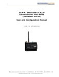
GC-10 Wireless Control Box
User Guide
GC-10
1. Introduction
This GC-10 Installation and User Guide will assist you in installing and configuring the
Brodersen GC-10 SMS Alarm Unit. The guide covers the installation of the configuration
software and gives a detailed description of the setup features. The guide is divided into
sections. The main parts are Software installation anda User Guide, describing the setup
of the GC-10 and the options available.
Wiring and installation details can be found in the GC-10 Installation Guide and further
information can be found on the Brodersen website www.brodersensystems.com,
where you will also find the latest news, programming examples and application
notes.
You can also obtain assistance from your local distributor.
40202 /03.10
2
GC-10
Index
1. Introduction ........................................................................................... 2
2. Index ..................................................................................................... 3
3. General Information .............................................................................. 4
3.1 Deliverables .................................................................................. 4
3.2 GC-10 Basic Functionality ............................................................ 4
4. Getting Started ..................................................................................... 5
5. User Guide ........................................................................................... 6
5.1 Starting GC-10 Configuration tool. ............................................... 6
5.2 Procedure for Setting up the GC-10 ............................................. 7
5.3 Saving and Restoring Configuration Data Files ........................... 7
5.4 Closing the GC-10 Configuration Tool and the Drivers. ............... 7
6. Setup and Configuration Parameters ................................................... 8
6.1 General about Configuration ........................................................ 8
6.2 Configuration – Alarm Module Config Tab Sheet ....................... 10
6.3 Configuration - SMS Message and Profiles Tab sheet ............... 13
6.4 Configuration – SMS Mobile No Tab Sheet ................................ 15
6.5 Configuration – Output Control Tab Sheet ................................. 16
6.6 Control Output with SMS from Mobile Phone ............................. 18
7. General Program Options ................................................................... 18
7.1 Selecting Language .................................................................... 18
7.2 Special Program Options ............................................................ 18
7.2.1 View System Log ....................................................................... 18
7.2.2 Lock at Last ............................................................................... 18
7.2.3 Clear the System Log ................................................................ 19
7.2.4 Add Msg to System Log ............................................................. 19
7.2.5 Save System Log As ................................................................. 19
7.2.6 Print System Log ....................................................................... 19
7.3 Help Options ............................................................................... 19
8. Uploading Log from GC-10 ................................................................. 20
8.1 Setting Upload Options ............................................................... 20
8.2 Structure and Format of Uploaded Data .................................... 23
8.3 Logged GC-10 Status Data .......................................................... 24
9. System Requirements ........................................................................ 26
10. Software Installation Guide ................................................................ 26
11. Un-installing the Software. ................................................................. 27
40202/03.10
3
GC-10
3. General Information
3.1 Deliverables
The GC-10 is delivered in a box containing all that is needed to start using the GC-10 SMS
Alarm Unit:
GC-10 SMS Alarm Unit.
Power Cable.
Configuration Cable.
GSM Antenna.
A CD with GC-10 Configuration Software.
GC-10 User Guide.
GC-10 Installation Guide.
3.2 GC-10 Basic Functionality
The GC-10 Wireless Control Box performs simple remote control functions, data
logging and communication via SMS messages using an integrated GSM modem.
The main features are:
•
Sending of SMS messages initiated by:
• Status change of digital input.
• Reaching a predefined setpoint on an analogue value – such as temperature
level or flow.
• Cyclic, at a predefined time.
•
Remote setting (On/Off) of digital outputs via an SMS message from a mobile
telephone.
•
Reporting input and output status on SMS request.
•
Real time alarm scheduling with profiles.
•
Simple control functions including a timer.
•
Local data logging with time stamp.
40202 /03.10
4
GC-10
4. Getting Started
Before starting we recommend that you read the User Guide and the Installation Guide.
Please pay special attention to the section dealing with electrical safety when working
with the GC-10.
Important: If you already have a version of Brodersen IOTOOL32 Pro on you PC, please
uninstall it prior to loading the GC-10 software when another version of IOTOOL32 Pro
will be installed.
The User and Installation Guide will take you through the installation and configuration
of the GC-10 step by step to ensure a trouble free operation:
•
Place a SIM card in the SIM cardholder. Make sure that the PIN code is disabled.
•
Fit the GSM antenna to the antenna plug.
•
Connect the power cable to the power supply terminals. Please note of the power
supply voltage printed on the label next to the power supply terminal.
•
Plug the configuration cable into the programming port on the top right corner of the
GC-10. Plug the Sub-D 9 pole into a free COM port on your PC (if you do not have
a COM port on your PC, you should use a USB-to-RS232 converter, and use aUSB
port instead).
•
Install the GC-10 configuration software on your PC, as per the instructions in the
Software Installation Section (see page 26).
•
Apply power to the GC-10 and wait for a connection to the GSM network (the modem
LED on the front of the GC-10 should start flashing slowly). If the modem LED is ON
constantly, the GC-10 is not connected to the GSM network. In which case check
that you have disabled the PIN code and that the SIM card works satisfactorily in a
mobile telephone.
You are now ready to start configuring the GC-10.
40202/03.10
5
GC-10
5. User Guide
5.1 Starting GC-10 Configuration Tool.
On your desktop you will find a GC-10 Config icon. Start the configuration tool by
double clicking on this icon.
During start up the required drivers will be initiated and you will see small pop-up
boxes with progress bars appearing and disappearing.
Finally the configuration tool will start the main user interface.
Use for connecting to GC-10
Use for uploading of log from
GC-10
Configuration Tab sheets
Button for downloading
of the configuration
parameters to GC-10
Open this User guide
Indicator for online with
GC-10
40202 /03.10
6
GC-10
5.2 Procedure for Setting Up the GC-10
Please make sure that the GC-10 is powered up.
Read the module data by clicking on Make Connections.
When the Rescan pop-up menu appears, you select the COM port used, no other
settings are needed. Select OK and the configuration software will scan the module to
confirm that a GC-10 is present.
After the rescan procedure is finished the module will be on-line. You can check the
connection in the Status Box (lower right corner). If it has turned green the GC-10 is online. If it has not turned green, check that the cable is correct, the module is powered up
and try to connect to the module again.
The GC-10 is now ready for setting up. All the adjustable parameters can be configured
in the Setup and Configuration Parameters section (see page 8). The configuration made
can be downloaded to the GC-10 unit by clicking the Download button.
5.3 Saving and Restoring Configuration Data Files
Settings/configuration made in the configuration tool can be saved by selecting File and
Save as…. The settings are saved in a project file (*.ini) which can be copied and used
on other PCs.
When you want to download the data from a saved project file, just connect the GC-10,
open the file and make sure that the GC-10 is on-line. Click Download and all the settings
from the file will be downloaded to the GC-10. If you want to store the settings to more
GC-10’s, just connect a new GC-10, apply power and click the Download button again.
Each time making sure that the module is on-line before downloading.
5.4 Closing the GC-10 Configuration Tool and the Drivers.
Important note: When you are running the configuration tool, the communication driver
requires the full service of the COM port and it does not accept any othe rprograms using
the COM port. After closing the software, you must close the basic driver. You will find
the driver icon on the bottom right side of your screen. Point at the icon, right click your
mouse and select ‘close‘ – now your COM port is clear for use by other programs.
40202/03.10
7
GC-10
6. Setup and Configuration Parameters
The configuration tool is designed to provide you with easy and simple configuration
features. It is important that you get familiar with the basic configuration strategy. (See
page 6)
•
Start with the ‘Alarm Module Config‘ tab sheet. Define which events should
initiate which actions.
•
Next enter the ‘SMS Message and Profiles‘ tab sheet. Enter SMS Message
texts and setup profiles of the SMS alarm message recipients.
•
The third step is to enter the ‘SMS Mobile No‘ tab sheet and enter all the mobile
numbers for receiving SMS alarm messages. Authorised telephone numbers allowed
to receive status messages and change outputs are also entered here.
•
Finally you enter the ‘Output Control‘ tab sheet. This is for configuring simple control
functions for outputs.
After setting up the parameters and functions, you save the configuration in a project file
(*.ini) and download the settings into the GC-10 by pressing the Download button.
We recommend that you follow the configuration flow diagram, see page 9, as the
selection options in a tab sheet may disable or enable the parameter settings on a
following tab sheet.
40202 /03.10
8
GC-10
Start
Alarm Module Config Tab
Define events and actions
SMS Message and Profiles
Define SMS alarms/status
texts.
Define profiles
(scheduling and SMS no.)
SMS Mobile no Tab
Define mobile numbers for
receiving alarm and
authentication (if required)
Output Control Tab
Define output control
parameters
Save to file
Down load
The procedure for remotely controlling outputs is described in section Controlling
output with SMS from mobile phone. (See 6.6 page 18)
40202/03.10
9
GC-10
6.2 Configuration – Alarm Module Config Tab Sheet (See fig. page 6)
Digital input Event Config
For each of the 4 digital inputs you can define what a rising pulse and/or falling pulse event
should do. Options are:
•
Activate SMS profile 1-3: Define which SMS profile an event should activate (see
page 15).
•
SMS Message: Defines the SMS message number to send. SMS number refers to
the SMS messages defined in the next tab sheet.
•
Log active: logs the event in the GC-10 with a time stamp.
NOTE: When powered up, the GC-10 will see an active input as a rising pulse event (if
only ‘rising pulse‘ box is ticked). If both ‘rising pulse‘ and ‘falling pulse‘ boxes are
ticked, no event is activated at power up until there is a change in the input.
40202 /03.10
10
GC-10
Analogue Input Event Config
The analogue inputs are 12-bit resolution (0-4095 bits). This means that minimum
input equals the value 0 and maximum input equals 4095.
For each of the 2 analogue inputs you can define:
•
Value = setpoint value in bits. If the analogue input value passes a defined setpoint
an event is activated. You can calculate the bit value from the following formula:
Setpoint value = 4096 x (setpoint – min. Input)
Max. value – min. value
Example: Input range is 4-20mA, setpoint wanted is 10mA.
Setpoint value = 4095 x ( 10mA – 4mA ) = 1535 bits
20mA – 4mA
•
Deadband: Define deadband (Hysteresis/window) in number of bits.
High Activated
AI Value
Deadband
Setpoint
Time
Alarm ON
Alarm OFF
40202/03.10
11
GC-10
LOW Activated
Deadband
AI Value
Setpoint
Time
Alarm ON
Alarm OFF
•
Scale: Define the scaling of the analogue input to be reported in SMS. Only the
values in the drop-down menu are allowed.
•
High/Low: Activate when setpoint is reached up and/or down.
•
Log: logs event with time stamp in GC-10.
•
SMS profile: Activate SMS profile 1-3. Define which SMS profile an event should
activate.
•
SMS Message: Defines the SMS message phone no. to send.
Time Event Config
Defines up to 6 cyclic activities for sending SMS and/or logging all inputs and outputs
in GC-10 log. The options are:
•
Active: Defines if a cyclic time event should be enabled.
•
Hour & minutes (time settings): Select at which time every day the cyclic event
should be performed.
•
Log All: All I/O values will be logged cyclically, as defined in the time setting
•
SMS profile: Activates SMS profile 1-3: Define which cyclic SMS profile should
be activated.
•
SMS Message: Define the SMS message number to send.
40202 /03.10
12
GC-10
6.3 Configuration - SMS Message and Profiles Tab Sheet
Layout
SMS Message
Up to 20 SMS texts can be entered in the SMS message chart. You can send an actual
analogue value by using the syntax #AI0 for the first analogue value and #AI1 for the
second analogue value. SMS texts numbered. 16-19 are by default configured for
sending status request messages. If NOT used they are available for other purposes.
The setting options are:
•
SMS Messages: Enter SMS messages. Can contain analogue values.
•
Enable status on request: Enable the option to get an I/O status SMS messages from
the GC-10 by sending a pre-defined SMS message from your mobile. See section
Status on request on following page.
40202/03.10
13
GC-10
SMS Profile
Define the 3 SMS profiles. SMS profiles can be used for scheduling alarm messages
to different users (mobile numbers) at different times of the day.
Each profile can contain 5 different numbers selectable from the Phone no. list. The
adjustments are:
•
•
•
Start hour: Define from when the profile is active
Stop hour: Define when profile is de-activated.
Phone nos.: Define the Phone nos. to be in the profile.
Status on Request
When ticked in the Enable box, you will enable the SMS request function. This
function makes it possible to send an SMS request to the GC-10 and ask for an I/O
status to be returned by SMS. 4 different options are available:
• “DI stat: 0,0,0,0” – report status of digital inputs
• “DO stat: 0,0,0,0” – report status of digital outputs
• “AI1 stat: 0” – report value of first analogue input as scaled.
• “AI2 stat: 0” – report value of second analogue input as scaled.
The text in the last 4 SMS texts (16-19) will automatically be used. Note that you can
add text, such as the site name to these messages.
In case you wish to reload these messages, cut and paste them:
•
•
•
•
Message 16 =
Message 17 =
Message 18 =
Message 19 =
DI stat: #DI0,#DI1,#DI2,#DI3
DO stat: #DO0,#DO1,#DO2,#DO3
AI0 stat: #AI0
AI1 stat: #AI1
Sending an SMS message “Cmdx” to the GC-10 will return a status SMS from the
GC-10 as follows.
• x = 1 reports DI status
• x = 2 reports DO status
• x = 3 reports first AI value
• x = 4 reports second AI value
CMD1
DI stat: 1,1,0,0
40202 /03.10
14
GC-10
6.4 Configuration – SMS Mobile No Tab sheet
Layout
SMS Phone No. list
SMS Mobile No.: Enter the list of mobile phone numbers to which SMS alarms are to
be sent.
Enter telephone number in the Telphone no list via SMS. (GC-10 v.2.05 and newer)
Up to five telephone numbers in the telephone list in the configuration table can be
entered with a SMS message. This is done by using the SMS format;
Cmdpno "phone no 0", "phone no 1", "phone no 2 ","... etc. - up to 5 numbers.
Example: Cmdpno "+45123456" - will write +45123456 into telephone no 0 in the list.
Existing number in the actual entry will be overwritten. If you do not enter any number but
just define "" the entry will be overwritten with blanks.
40202/03.10
15
GC-10
GSM Providers Short Message Service Centre No. (SMSC)
The SMS Service Centre Number can be obtained from the GSM provider. Some
providers do not use a SMSC number as they can automatically route SMS messages
to the SMS Service centre, if such is the case leave blank.
SMS Command Security
Defines the phone numbers authorised to receive status messages from the GC-10 and
to control outputs with SMS messages. If no phone numbers are entered, authentication
is not activated and all valid messages are accepted
6.5 Configuration – Output Control Tab sheet
Layout
Controlling Output
Each output can be controlled by an event and cyclic activities of a DI and AI. A timer
function is possible for output 0 (first output). The timer is started whenever a control
event is activated for output 0.
40202 /03.10
16
GC-10
5 different events can control the outputs:
• DIx: Digital input change.
• AIx: Analogue value reaching a setpoint.
• Tx: Cyclic time event.
• Timer: On-delay or off-delay timer function.
• CMD: Command SMS from mobile phone. By default all outputs can be controlled
from an SMS command message. If an output is not to be controlled from an SMS
command the box should be left blank.
The “On” and “Off” tick boxes provide the following functions:
• Ticking the “On” box will activate the output at the specific event.
• Ticking the “Off” box will de-activate the output at the specific event.
Ticking both the “On” and “Off” boxes will activate the output when – and only when
the specific event is activated.
Note: an output can be controlled by more than one input event. E.g. an output can
be activated by input 0 and de-activated by input 1.
Timer settings:
• When ticking the “On” box an On-delay function is provided for output 0.
• When ticking the “Off” box an Off-delay function is provided for output 0.
When you enable a timer function it is linked in between the event that controls output
0 and output 0. Enabling the timer alone does not give any function.
Ticking in Timer ON makes a simple a delay in the output going ON and ticking in
Timer OFF makes a delay in the output going OFF. It makes no difference whether it
is input event or a cyclic event that is set to activate the output.
Example:
If an input event is to directly activate/deactivate an output and you enable Timer ON
– the function will be as shown in Fig. 1. I.e. the input has to be ON for longer than the
time delay before the output is activated.
Fig. 1
T
T
T
T
Event: DIx, AIx or Tx
DO0 On-delay
DO0 Off-delay
T= Time Setting
40202/03.10
17
GC-10
CMD settings:
The CMD (Command) box must be ticked, to enable control with SMS message from
a mobile phone.
Time settings:
Timing period is defined in seconds.
6.6 Control Output with SMS from Mobile Phone
Outputs can be controlled remotely via an SMS message.
By sending an SMS message to the GC-10 you can activate or de-activate an output.
Sending an SMS message “Cmdxx” to the GC-10, where “xx” defines the action, will
activate or de-activate the outputs.
Sending an SMS message „AckCmdxx“ will both activate or de-activate the outputs and
return an SMS message to confirm execution of the command or not.
An action is defined by “xx” from the following list:’
• xx = 10 De-activate output 0 (1st output)
• xx = 11 Activate output 0 (1st output)
• xx = 20 De-activate output 1 (2nd output)
• xx = 21 Activate output 0 (2nd output)
• xx = 30 De-activate output 3 (3rd output)
• xx = 31 Activate output 2 (3rd output)
• xx = 40 De-activate output 3 (4th output)
• xx = 41 Activate output 3 (4th output)
Note: text is not case sensitive.
7 General Program Options
7.1 Selecting Language
In the Option menu you are able to change language. After changing the language the
program must be re-started to use the selected language. At present only English and
German languages are supported, but other languages will be added as and when
required.
7.2 Special Program Options
The configuration tool has some helpful options, which you will find in the System Log
drop-down menu. The options are listed below.
7.2.1 View System Log
If you activate view system log you will get an extra window at the bottom of your
configuration tool. It is a system log which reports all events and activities performed by
the driver communicating with the GC-10. Useful if connecting to the GC-10 is a problem.
40202 /03.10
18
GC-10
7.2.2 Locking at Last Log
Default activated means that the configuration tool will scroll the system log so the
last log line is always viewable in the system log window.
7.2.3 Clear the System Log
Clears the system log.
7.2.4 Add Msg to System Log
This feature allows you to add comments to the System Log by a prompt in the
dialogue box below.
7.2.5 Saving System Log
Saves the System Log in a file.
7.2.6 Print System Log
Prints the System Log on the printer.
7.3 Help Options
Under the Help drop-down menu you will find the software information and version.
Help for using the program is basically only in this document and in the help and
information line at the bottom of the screen. There is no F1 help.
40202/03.10
19
GC-10
8. How to Upload Saved Data from the GC-10
Logged data can be uploading from the GC-10 to a PC using the same RS232 cable
used in configuring the GC-10. After communication has been established you are
able to empty the GC-10 Log Buffer using the upload facility.
When clicking the Upload Log Icon the following menu appears:
This is the Upload Log Main Menu, where you can set the parameters for the upload
routine.
Graphical view showing
the Nets and Nodes.
Node 1 symbolises the GC-10
Information about
last time the GC10 was uploaded
and the filename
used.
8.1 Setting Upload Options
Before you start uploading a log file you must define the log upload options.
The first entry is to specify the directory in which to place the logged data after it has been
uploaded.
This is done by choosing the Select Directory command in the File Menu.
The following dialogue box appears. Select the required directory and press OK.
40202 /03.10
20
GC-10
Directory in which to
place log data
In this example the C:\RTULOG directory has been selected.
The Option Menu gives you a number of choices of how to save your uploaded data,
and a number of parameter settings of the upload format.
40202/03.10
21
GC-10
File name and filing options
3 options are available:
•
•
•
Save Log in LOG.CSV (use same file for all log uploads).
Save Log in MMDDxxxx.CSV format (MM=month, DD=day, xxxx=number of
upload).
Save Log in MMDD.CSV format (MM=month, DD=day).
File format
Always use CSV format which is pure text file
Update time in node
Tick if you want the GC-10 internal clock to be synchronised to the PC time at every log
upload.
Enter automode options
Not used.
Upload all
Tick if you want a full upload of all data from the GC-10. If not ticked only logged data since
last log upload will be uploaded.
Format of 100th of second
Enable or disable use of 100th of a second in the log time stamp.
Starts upload
Current record
to be uploaded.
Time stamp.
40202 /03.10
22
GC-10
IIf you have ticked the Use MMDDxxxx.CSV format in the Options; File Name and
Filing Options Menu, the uploaded files will be saved as follows:
The first file uploaded on the 18 of February will be named 02180000.CSV, the second
02180001.CSV and so on.
8.2 Structure and Format of Uploaded Data
After uploading of the data you can view the generated comma separated ASCII log file
using an editor or by importing it into a spreadsheet such as Microsoft Excel. Each item
of logged data is defined by an id. Shown below is an example of how the data is
structured in the log file:
Log id
0
1
2
3
4
5
6
7
8
9
10
11
> 130
Log file structure
I/O
Date
Time
Log id I/O data
DI 0 18-02-04 10:09:10; 0;
;1
DI 1 18-02-04 10:09:25; 1;
;1
DI 2 18-02-04 10:09:45; 2;
;0
DI 3 18-02-04 10:09:55; 3;
;0
AI 0 18-02-04 10:10:13; 4;
;50
AI 1 18-02-04 10:10:35; 5;
;100
T0
18-02-04 10:10:51; 6;
;1;1;0;0;0;0;1;1;50;100
T1
18-02-04 10:11:16; 7;
;1;1;0;0;0;0;1;1;50;100
T2
18-02-04 10:11:32; 8;
;1;1;0;0;0;0;1;1;50;100
T3
18-02-04 10:11:13; 9;
;1;1;0;0;0;0;1;1;50;100
T4
18-02-04 10:12:13; 10;
;1;1;0;0;0;0;1;1;50;100
T5
18-02-04 10:12:13; 11;
;1;1;0;0;0;0;1;1;50;100
Status loggs - see next page.
The I/O data in the T0..T5 logs is structured as:
; DI0 ; DI1 ; DI2 ; DI3 ; DO0 ; DO1 ; DO2 ; DO3 ; AI0 ; AI1
Digital inputs and digital outputs is logged as the value 0 or 1, where 0 = OFF and
1 = ON.
Analogue input values are logged as the chosen scaled value. If you have selected the
scale to be 0-4095, a maximum input will be logged as the decimal value 4095.
If the analogue inputs are logged as decimal values 0-4095 (0 = min. input and 4095 =
max. input) you have to calculate the real value (e.g. a temperature or another signal input
level.
40202/03.10
23
GC-10
Example:
If the analogue input is a temperature Pt100 input with a range of -50 - 100 degrees
Celsius, the logged value 1051 equals the temperature of:
( (100-(-50)) / 4095 x 1051 ) + (-50) = -11,5 degrees Celsius.
If you use MS Excel you can make the calculations there and get the real readings
reported directly.
Upload of log data is in the file started with:
Station number;1
Up-load start;18-02-04 10:20:39
and ended with:
Station number;1
Up-load end;18-02-04 10:20:39
8.3 Logged GC-10 Status Data
Below is a list covering the pre-defined log IDs used.
Event
Log ID
Power ON and/or micro processor reset
130
Program download or change of set-up
131
Errors detected by the controller.
(Status error/communication error, etc.)
150
The log memory has been up-loaded
(the PC will request this log to take place)
170
Log buffer overflow
171
Log ID in application out of range
172
Clock has been updated
180
40202 /03.10
24
GC-10
9. System Requirements
Minimum requirements for running the GC-10 configuration software:
Hardware:
IBM compatible PC with a Pentium Processor
32 MB RAM
30 MB free hard disk space
Mouse and keyboard
SVGA monitor (minimum display resolution: 768 x 1024, Small Fonts)
CD-ROM or DVD drive.
1 serial RS232 COM port.
Software:
32 bit operating system
MS Windows2000, NT4.0 or WindowsXP.
10. Software Installation Guide
Before you start installation of the software, please make sure that you do not have any
prior versions of GC-10 configuration software or IOTOOL32Pro installed. If you have,
you should un-install by using the Add or Remove Program option in the Control Panel.
Place the installation CD in your CD drive and if autorun is enabled on your PC the
installation will start automatically. If not you should type D:\setup in the Run windows
located under the Start button on your MS Windows desktop.
Now the installation of the software is in progress. In general you just enter Next at every
installation screen.
When the GC-10 configuration software is installed on your PC and ready to use an icon
will appear on the desktop.
When using the GC-10 configuration software to generate a configuration file, the GC10 must be connected to the PC as some parts of the setup require a direct reading in
the GC-10 for showing the setup options. When you have made a configuration setup on
one unit you will be able to store the settings in a project file. The project file will contain
all settings and you can easily copy the project file to other computers for downloading
the GC-10 setting into other GC-10’s.
40202/03.10
25
GC-10
Important note: When you are running the GC-10 configuration software, you are using
a serial driver on the COM port. The driver requires full service from the COM port and
it does not accept any other programs using the COM port.
After closing the GC-10 configuration software, you must close the basic driver. You find
the driver icon
on the bottom right side of your screen. Point at the icon, right click your mouse and close
the driver - now your COM port is free for use by other programs.
Point at this icon
11. Un-installing the Software.
The software is un-installed by entering the Add or Remove program facility in Windows
Control Panel and un-install GC-10 configuration software. If during un-installation you
see the message “You must close all drivers before uninstalling“, please refer to Section
10 above.
Note: This document is subject to changes without notice.
40202 /03.10
26
GC-10
40202/03.10
27
GC-10
40202 /03.10
28