1
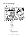
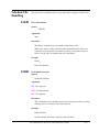
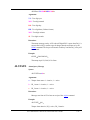
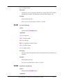
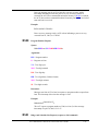
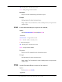
The digital inputs each have five terminals: DI–, DI+, Vcc (+5V), shield, and
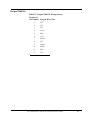
ground. Table 2-3 identifies the pin numbers for the digital inputs.
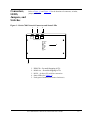
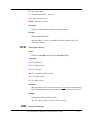
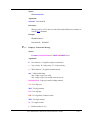
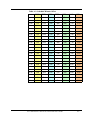
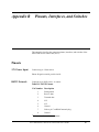
Table 2-3: ACU DI Connections
Pin Number
Description
1
Shield
2
Ground
3
DI -
4
DI +
5
Vcc (+5v)
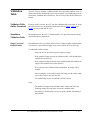
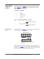
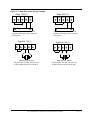
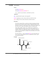
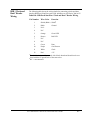
In an inactive state, DI– should be pulled low (connected to ground) and DI+ pulled
high (connected to Vcc). If either of those connections is broken, the digital input
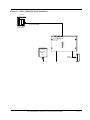
will signal alarm state. For the installation shown in Figure 2-1, connect a normally
open magnetic switch between DI– and ground of DI_1. Put a jumper between DI+
and Vcc. (Or, you could put the magnetic switch between DI+ and Vcc, and the
jumper between DI– and ground. The effect is the same.) Connect the wire’s shield,
if any, to the shield terminal.
Digital IN 1 (DI_1)
Vcc
DI+
DI-
Gnd
Introduction
Wiring the Digital
Inputs (DI_1 and
DI_2)
Shd
Magnetic Door Sensor
When contact is broken, DI_1 enters
alarm state and can trigger DO_2 to
sound alarm.
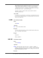
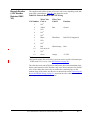
In the installation being described, DI_2 is not used. Place jumpers between DI–
and ground, and between DI+ and Vcc, of DI_2 to disable it.
Digital IN 2 (DI_2)
Vcc
DI+
DI-
Gnd
Shd
DI_2 not used. DI+ and DI- connected to
power and ground to prevent ACU from
entering alarm state.
Accu-Time® Series 7000 Access Control Unit User’s Guide
2-8