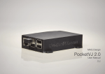
1
Beaglebone cape INTERNET HUB INTERNET HUB User Manual Code : Version : Date : INTERNETHUB-MANUAL-EACH-1.0 1.0 20/12/2014 INTERNET HUB User Manual Page intentionally left blank © EACH, Lda Version : 1.0 Date : 20/12/2014 Page : 2 of 25 INTERNET HUB User Manual Version : 1.0 Date : 20/12/2014 Page : 3 of 25 Warranty, Warnings and Disclaimers This evaluation board/kit is intended for use for ENGINEERING DEVELOPMENT, DEMONSTRATION, OR EVALUATION PURPOSES ONLY and is not considered by EXPLOITSYS to be a finished end product fit for general consumer use. Persons handling the product(s) must have electronics training and observe good engineering practice standards. As such, the goods being provided are not intended to be complete in terms of required design-, marketing-, and/or manufacturing-related protective considerations, including product safety and environmental measures typically found in end products that incorporate such semiconductor components or circuit boards. This evaluation board/kit does not fall within the scope of the European Union directives regarding electromagnetic compatibility, restricted substances (RoHS), and therefore may not meet the technical requirements of these directives or other related directives. Please read the User Manual and, specifically, the Warnings and Restrictions notice in the Systems Reference Manual of the BeagleBone you are using, prior to handling the product. This notice contains important safety information about temperatures and voltages. No license is granted under any patent right or other intellectual property right of Supplier covering or relating to any machine, process, or combination in which such Supplier products or services might be or are used. The Supplier currently deals with a variety of customers for products, and therefore our arrangement with the user is not exclusive. The Supplier assumes no liability for applications assistance, customer product design, software performance, or infringement of patents or services described herein. The BB-BONE-GPS-GPRS as purchased is warranted against defects in materials and workmanship for a period of 90 days from purchase. This warranty does not cover any problems occurring as a result of improper use, modifications, exposure to water, excessive voltages, abuse, or accidents. All boards will be returned via standard mail if an issue is found. If no issue is found or express return is needed, the customer will pay all shipping costs. © EACH, Lda INTERNET HUB User Manual Page intentionally left blank © EACH, Lda Version : 1.0 Date : 20/12/2014 Page : 4 of 25 INTERNET HUB User Manual 1.0 Version : Date : 20/12/2014 Page : 5 of 25 Revision History Version 1.0 Changes Document creation © EACH, Lda Date Approved 20/12/2014 DCarona INTERNET HUB User Manual Page intentionally left blank © EACH, Lda Version : 1.0 Date : 20/12/2014 Page : 6 of 25 INTERNET HUB User Manual Version : 1.0 Date : 20/12/2014 Page : 7 of 25 Table of Contents 1. Introduction .................................................................................................................................. 11 1.1. Scope ................................................................................................................................................... 11 1.2. Acronyms and Abbreviations............................................................................................................ 11 2. Related Documents ...................................................................................................................... 12 2.1. Reference documents ......................................................................................................................... 12 3. Pin Description ............................................................................................................................. 13 3.1. RESIN_IN........................................................................................................................................... 14 3.2. W_DISABLE ...................................................................................................................................... 14 3.3. WAKE ................................................................................................................................................ 15 3.4. User Led ............................................................................................................................................. 15 4. Interacting with GPIO’s .............................................................................................................. 16 5. Power ............................................................................................................................................. 17 6. Initial Setup .................................................................................................................................. 18 6.1. WiFi USB Driver ................................................................................................................................ 18 Angstrom ................................................................................................................................................ 18 Debian ..................................................................................................................................................... 19 6.2. Cape Firmware .................................................................................................................................. 20 6.3. Antennas ............................................................................................................................................. 20 7. Using Cape .................................................................................................................................... 21 7.1. Manual Process (every time BB boots up) ....................................................................................... 22 7.1.1. HSDPA Communication protocol ................................................................................................. 22 7.1.2. GPS Communication ..................................................................................................................... 23 Start GPS................................................................................................................................................. 23 Stop GPS ................................................................................................................................................. 23 8. WiFi ............................................................................................................................................... 24 8.1. Access Point ........................................................................................................................................ 24 8.1.1. HostAPD (Access Point Configuration) ........................................................................................ 24 © EACH, Lda INTERNET HUB User Manual Page intentionally left blank © EACH, Lda Version : 1.0 Date : 20/12/2014 Page : 8 of 25 INTERNET HUB User Manual Version : 1.0 Date : 20/12/2014 Page : 9 of 25 List of Figures Fig. 3-1 – P9 Pin location in BeagleBone Black. ............................................................................................ 14 Fig. 3-2 – Reset pulse duration. ...................................................................................................................... 14 Fig. 3-3 – WAKE pin pulse duration. ............................................................................................................. 15 Fig. 6-1 – Antennas connectors. ..................................................................................................................... 20 Fig. 7-1 – List of devices of INTERNET HUB cape. ..................................................................................... 21 List of Tables Table 2-1 – Related Documents ..................................................................................................................... 12 Table 3-1 – P9 Header pin usage. ................................................................................................................... 13 Table 3-2 – User Led state description. .......................................................................................................... 15 Table 6-1 – Module antenna connectors. ........................................................................................................ 20 Table 7-1 – List of USB devices created by the module. ................................................................................ 21 © EACH, Lda INTERNET HUB User Manual Page intentionally left blank © EACH, Lda Version : 1.0 Date : 20/12/2014 Page : 10 of 25 INTERNET HUB User Manual 1.0 Version : Date : 20/12/2014 Page : 11 of 25 1. INTRODUCTION The INTERNET HUB Cape described in this document adds GSM/HSDPA, GPS, WiFi and extra USB ports capabilities to the BeagleBone making it suitable for tracking and for remote monitoring scenarios. The cape uses Huawei MU609, a high quality module with proven performance and reliability. This cape supports the Quad band GSM/GPRS (850 MHz, 900MHz, 1800MHz, 1900MHz and 2100MHz). 1.1. Scope This document describes the cape’s behaviors and features, and also how to interact with it. 1.2. Acronyms and Abbreviations The acronyms and abbreviations used in the present document are: Acronym BB BBB HSDPA Description BeagleBone BeagleBone Black High-Speed Downlink Packet Access GPS Global Positioning System I/O Input/Output RD Reference Document © EACH, Lda INTERNET HUB User Manual 1.0 Version : Date : 20/12/2014 Page : 12 of 25 2. RELATED DOCUMENTS 2.1. Reference documents Table 2-1 specifies which reference documents should be considered when following this document. Table 2-1 – Related Documents Reference Title Version Date Rev A5.2 04/2013 [RD 1] BeagleBone Black System Reference Manual [RD 2] MU609 Hardware User Guide Rev. 01 06-01-2014 [RD 3] MU609 Application Guide Rev. 01 04-08-2013 © EACH, Lda INTERNET HUB 1.0 Version : User Manual Date : 20/12/2014 Page : 13 of 25 3. PIN DESCRIPTION This cape has been developed to be fully compatible with BeagleBone Black, therefore based on Error! Reference source not found. the pin map from BB perspective (I/O) for BBB is the following: Table 3-1 – P9 Header pin usage. Pin Name on Cape Name on BBB Pin to Export Mode Direction P9.25 RESIN_IN GPIO3_21 117 7 O P9.27 W_DISABLE GPIO3_19 115 7 O P9.42 WAKE GPIO0_7 7 7 O © EACH, Lda INTERNET HUB User Manual Version : 1.0 Date : 20/12/2014 Page : 14 of 25 Fig. 3-1 – P9 Pin location in BeagleBone Black. 3.1. RESIN_IN The MU609 module supports hardware reset function. If the software of the MU609 module stops responding, you can reset the hardware through the RESIN_N signal as shown in Fig. 3-2. When a low-level pulse is supplied through the RESIN_N pin, the hardware will be reset. The RESIN_IN pin should not be pulled down more than 1s. Fig. 3-2 – Reset pulse duration. 3.2. W_DISABLE The W_DISABLE# signal is provided to allow users to disable wireless communications of the module. In this mode the power consumption of the module is about 2mA. © EACH, Lda INTERNET HUB Version : User Manual 1.0 Date : 20/12/2014 Page : 15 of 25 3.3. WAKE WAKE# pin (signal that the module uses to wake up the host) supports software control. This signal is used for 3G module to wake up the host. It is designed as an OC gate, so the cape includes a pull up resistor of 10kΩ to ensure the high state. This pin is active-low. When the module wakes up the host, the WAKE# pin will output low-level-voltage to wake the host. Fig. 3-3 – WAKE pin pulse duration. 3.4. User Led The led present on the cape is connected to the module and represents the state of the module depending on the mode enabled. Table 3-2 describes each state. Table 3-2 – User Led state description. State 1 Operating Status Led Beahviour No service/Restricted service Outputs: low(0.1s)-high (0.1s)low(0.1s)-high (1.7s) 2s cycle 2 3 Register to the network Outputs: low (0.1s)-high (1.9s) 2s cycle Dial-up successfully © EACH, Lda Outputs: low INTERNET HUB User Manual Version : 1.0 Date : 20/12/2014 Page : 16 of 25 4. INTERACTING WITH GPIO’S To interact with BB GPIO’s, it is required to export the pin so the user can have access to it. In order to know the pin number that corresponds to a certain GPIO the following formula can be used: GPIOx_y = x*32 + y Example: GPIO1_6 = 1*32 + 6 = 38 The pin that has to be exported is “pin 38”. After discovering pin number the following procedure should be adopted: 1. Select the folder that controls GPIO’s a. cd /sys/class/gpio/ 2. Choose which pin to export a. echo 38 > export 3. Select the exported pin file a. cd /sys/class/gpio/gpio38 4. Set pin direction a. echo in > direction 5. Read pin a. cat value If pin is set to work as output the procedure is the same but in direction file should be echoed “out” instead of “in” and to affect the pin “1” or “0” should be echoed to value file. © EACH, Lda INTERNET HUB User Manual Version : 1.0 Date : 20/12/2014 Page : 17 of 25 5. POWER The INTERNET HUB cape has been developed to be powered only through USB, however we recommend the usage of external power supply of 5V @ 1A because in some cases the network connection might request a raise on the transmitting power of the module and cause some issues on the BBB power supply. © EACH, Lda INTERNET HUB User Manual Version : 1.0 Date : 20/12/2014 Page : 18 of 25 6. INITIAL SETUP Before plug in BB-INTERNET-HUB cape into user beaglebone for the first time, some steps need to be followed: 6.1. WiFi USB Driver The WiFi USB driver on BBB has some issues that need to be fixed in order the WiFi can work properly. Below are described the steps to fix the issues for Angstrom and Debian distributions. Angstrom apt-get apt-get apt-get apt-get update upgrade install kernel-dev install kernel-headers You may need to reboot. cd /usr/src/kernel make scripts ln -s /usr/src/kernel /lib/modules/$(uname -r)/build cd ~ git clone git://github.com/cmicali/rtl8192cu_beaglebone.git cd rtl8192cu_beaglebone make CROSS_COMPILE="" Install the driver mv 8192cu.ko /lib/modules/$(uname -r) depmod -a cd /etc/modules-load.d echo "8192cu" > rtl8192cu-vendor.conf Blacklist the old rtlwifi drivers cd /etc/modprobe.d echo "install rtl8192cu /bin/false" > wifi_blacklist.conf echo "install rtl8192c_common /bin/false" > wifi_blacklist.conf echo "install rtlwifi /bin/false" > wifi_blacklist.conf Edit /var/lib/connman/settings and enable WIFI [global] OfflineMode=false [Wired] Enable=true Tethering=false © EACH, Lda INTERNET HUB User Manual 1.0 Version : Date : 20/12/2014 Page : 19 of 25 [WiFi] Enable=true Tethering=false Shutdown your BBB, plug in your INTERNET HUB cape along with the USB cable and reboot. Debian opkg opkg opkg opkg update upgrade install kernel-dev install kernel-headers cd /usr/src/linux-headers-3.8.13-bone47 make scripts ln -s /usr/src/linux-headers-3.8.13-bone47 /lib/modules/$(uname -r)/build cd ~ Fix a problem with the timex.h header vi /usr/src/linux-headers-3.8.13-bone47/arch/arm/include/asm/timex.h change line 18 from #include <mach/timex.h> To #include </usr/src/linux-headers-3.8.12-bone17/arch/arm/include/asm/timex.h> Get the new driver and compile it git clone git://github.com/cmicali/rtl8192cu_beaglebone.git cd rtl8192cu_beaglebone make CROSS_COMPILE="" Install the driver mv 8192cu.ko /lib/modules/$(uname -r)/kernel/drivers/net/wireless/ depmod cd /etc/modules-load.d echo "8192cu" > rtl8192cu-vendor.conf Blacklist the old rtlwifi drivers cd /etc/modprobe.d echo "blacklist rtl8192cu" > wifi_blacklist.conf echo "blacklist rtl8192c_common" > wifi_blacklist.conf echo "blacklist rtlwifi" > wifi_blacklist.conf © EACH, Lda INTERNET HUB User Manual 1.0 Version : Date : 20/12/2014 Page : 20 of 25 Shutdown your BBB, plug in your INTERNET HUB cape along with the USB cable and reboot. 6.2. Cape Firmware Insert the file INTERNET-HUB-00A0.dtbo supplied with the cape into the firmware folder: cp INTERNET-HUB-00A0.dtbo /lib/firmware/ 6.3. Antennas Fig. 6-1 – Antennas connectors. The module has three UF.L connectors for antennas and Table 6-1 describes each connector. Table 6-1 – Module antenna connectors. Label Description AUX Auxiliary connector for range extender GPS GPS passive antenna connector MAIN GSM antenna connector © EACH, Lda INTERNET HUB User Manual Version : 1.0 Date : 20/12/2014 Page : 21 of 25 7. USING CAPE When the cape is plugged in the BBB and connected to USB a list of several USB devices appears available according with Fig. 7-1 and typing “lsusb -t” in your BBB console. Fig. 7-1 – List of devices of INTERNET HUB cape. Each USB device has a role on the interaction with the module, as described on Table 7-1. Table 7-1 – List of USB devices created by the module. Port Description ttyUSB0 AT Commands for module ttyUSB1 ttyUSB2 GPS AT Commands ttyUSB3 GPS NMEA messages ttyUSB4 © EACH, Lda INTERNET HUB User Manual 1.0 Version : Date : 20/12/2014 Page : 22 of 25 7.1. Manual Process (every time BB boots up) Enable cape: echo INTERNET-HUB > /sys/devices/bone_capemgr.*/slots After, the cape is enabled on user BeagleBone and ready to be used. To validate that operation has been succeeded you can type: cat /sys/devices/bone_capemgr.*/slots If the cape firmware is correctly loaded the cape name is shown. 7.1.1. HSDPA Communication protocol IMPORTANT NOTE: It is recommend that the SIM card used in your cape has its PIN code disabled. Some users reported problems when using PPPD with the SIM card PIN code active, so for correct functioning your SIM card should have its PIN code disabled. In order to register the module in the network the user need to insert the SIM card on the connector and use a serial port tool like minicom to open /dev/ttyUSB0. When ttyUSB0 is opened please type: AT+COPS? //check if has any network AT^NDISDUP=1,1,”APN” // dial-up, “APN” should be changed to the real settings If success you should receive ^NDISSTAT:1,,,”IPV4” After that minicom can be closed and using the command “ifconfig” is possible to check the name of the new interface created by the module, probably you will have a name like “rename3”. © EACH, Lda INTERNET HUB User Manual Version : 1.0 Date : 20/12/2014 Page : 23 of 25 On the shell input of your BBB type: dhclient rename3 // Or other name ifconfig to check that the interface has a new IP address assigned. If it is only up without IP address and the led of the module is always ON, retype the same dhclient command and recheck. For more options on how to configure the module please refer to [RD 3]. 7.1.2. GPS Communication Start GPS To start GPS the user needs to open minicom with /dev/ttyUSB2 and type the following commands: AT^WPDOM=0 //Sets the positioning method to Standalone AT^WPDST=1 //Sets the session type to tracking positioning AT^WPDGP //Starts positioning Periodically this interface receives the position information, instead the user can open minicom with /dev/ttyUSB3 to get the NMEA messages produced by the module. IMPORTANT NOTE: Since the GPS antenna used by the module is passive, to get position the cape needs to be close to a window. Stop GPS To stop GPS acquisition the user only needs to execute the following AT command on /dev/ttyUSB2: AT^WPEND For more options on how to configure the GPS please refer to [RD 3]. © EACH, Lda INTERNET HUB User Manual 1.0 Version : Date : 20/12/2014 Page : 24 of 25 8. WIFI 8.1. Access Point If the user decide to use the INTERNET HUB as an access point we suggest the installation of HostAPD to facilitate the configuration of the module. 8.1.1. HostAPD (Access Point Configuration) 1. Install the standard hostapd so you don't have to create your own startup script, etc..., you might get error here... just ignore them since you will compile your own version. apt-get install hostapd 2. Get modified hostapd for Realtek wget https://github.com/jenssegers/RTL8188-hostapd/archive/v1.1.tar.gz 3. Unzip tar -zxvf v1.1.tar.gz 4. Build it cd RTL8188-hostapd-1.1/hostapd make 5. Install it make install 6. Move it into the correct location and replace the old one mv hostapd /usr/local/bin 7. Edit /etc/hostapd/hostapd.conf # Basic configuration interface=wlan0 ssid=BeagleBoneBlack channel=1 #bridge=br0 # WPA and WPA2 configuration macaddr_acl=0 auth_algs=1 ignore_broadcast_ssid=0 wpa=3 wpa_passphrase=AnhIsAwesome! wpa_key_mgmt=WPA-PSK wpa_pairwise=TKIP © EACH, Lda INTERNET HUB User Manual 1.0 Version : Date : 20/12/2014 Page : 25 of 25 rsn_pairwise=CCMP # Hardware configuration driver=rtl871xdrv ieee80211n=1 hw_mode=g device_name=RTL8192CU manufacturer=Realtek 8. Edit /etc/default/hostapd # Defaults for hostapd initscript # # See /usr/share/doc/hostapd/README.Debian for information about alternative # methods of managing hostapd. # # Uncomment and set DAEMON_CONF to the absolute path of a hostapd configuration # file and hostapd will be started during system boot. An example configuration # file can be found at /usr/share/doc/hostapd/examples/hostapd.conf.gz # DAEMON_CONF="/etc/hostapd/hostapd.conf" # Additional daemon options to be appended to hostapd command:# -d show more debug messages (-dd for even more) # -K include key data in debug messages # -t include timestamps in some debug messages # # Note that -B (daemon mode) and -P (pidfile) options are automatically # configured by the init.d script and must not be added to DAEMON_OPTS. # #DAEMON_OPTS="" © EACH, Lda