1
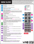
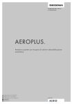
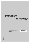
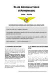
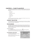
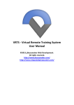
FLIGHT TRACKER
V2.04-D
USER’S MANUAL
Doc: FT2DU030411B
May 2013
Montreal AeroPlus, 685 Orly, Montreal, QC, H9P 1G1 Canada
Flight Tracker 2.04-D User Manual
Page 2 of 14
Changes: Rev B May 2013 RDP – Document formatting changes, changes for Version
2.04-Digital :Graphics replaced, added Center on Mouse and About functions, Installer
modified.
Table of Contents
1.0 Introduction........................................................................................................................3
2.0 Minimum System Requirements.......................................................................................3
3.0 Flight Tracker Software Operation....................................................................................4
3.1 General Overview............................................................................................................... 4
3.2 MAP Menu Functions......................................................................................................... 5
3.2.1 CNTR ON A/C...............................................................................................5
3.2.2 NORMAL ZOOM...........................................................................................5
3.2.3 ZOOM IN.......................................................................................................5
3.2.4 ZOOM OUT...................................................................................................5
3.2.5 STOPWATCH...............................................................................................5
3.2.6 SAVE IMAGE................................................................................................6
3.2.7 REDRAW MAP.............................................................................................6
3.2.8 ERASE PATH...............................................................................................6
3.2.9 MAP FEATURES..........................................................................................6
3.2.10 CTR MOUSE...............................................................................................6
3.2.11 ABOUT FT2................................................................................................7
3.2.12 SLEW ON/OFF...........................................................................................7
3.2.13 MAINTENANCE..........................................................................................7
3.2.14 EXIT............................................................................................................7
3.3 MAINTENANCE Menu Functions.......................................................................................8
3.3.1 CNTR ON A/C...............................................................................................9
3.3.2 LAT / LON.....................................................................................................9
3.3.3 ZOOM IN.......................................................................................................9
3.3.4 ZOOM OUT...................................................................................................9
3.3.5 CAL POINT #1..............................................................................................9
3.3.6 CAL POINT #2............................................................................................10
3.3.7 CAL POINT #3............................................................................................10
3.3.8 CALIBRATE................................................................................................10
3.3.9 CTR MOUSE...............................................................................................10
3.3.10 SLEW ON/OFF.........................................................................................11
3.3.11 SAVE SETUP...........................................................................................11
3.3.12 PREV MENU.............................................................................................11
3.4 CALIBRATION PROCEDURE..........................................................................................12
3.5 MAP FEATURES Menu Functions...................................................................................13
4.0 Frequently Asked Questions...........................................................................................14
5.0 Technical Support...........................................................................................................14
Montreal AeroPlus, 685 Orly, Montreal, QC, H9P 1G1 Canada
FT2DU030411 Rev B
May 2013
Flight Tracker 2.04-D User Manual
Page 3 of 14
1.0 Introduction
Flight Tracker is an enhancement designed to work through a personal computer. It
replaces the mechanical pen plotter supplied with the ATC810 flight training device (FTD).
It uses a digital interface card, which is connected to the computer’s printer port. It
provides precise real-time tracking of the simulated aircraft’s position.
Included in the software are features to enhance its training value such as user definable
land features, Zoom and Pan features, and storage of the map and track in a standard
bitmap graphics file format (BMP), which can be easily printed using any Photo Paint
software.
2.0 Minimum System Requirements
-
Personal computer (Pentium I or better)
256 k memory
1 GB hard disk
Compatible SVGA video card
Mouse
Standard, EPP or ECP Parallel printer interface
Windows XP operating System.
Note: Flight Tracker V2.04D has not been tested on Windows 9X, 2000.
Montreal AeroPlus, 685 Orly, Montreal, QC, H9P 1G1 Canada
FT2DU030411 Rev B
May 2013
Flight Tracker 2.04-D User Manual
3.0
Page 4 of 14
Flight Tracker Software Operation
Start Flight Tracker by double clicking the desktop icon:
3.1
General Overview
All functions required during training are accessed from the buttons on the right side
of the screen as shown below:
The bottom of the screen displays:
- Simulated aircraft’s latitude and longitude
- Stopwatch elapsed time
- Magnetic bearing and distance from the aircraft to the mouse
- Status of the slew function
Montreal AeroPlus, 685 Orly, Montreal, QC, H9P 1G1 Canada
FT2DU030411 Rev B
May 2013
Flight Tracker 2.04-D User Manual
3.2
Page 5 of 14
MAP Menu Functions
The MAP MENU functions are accessed by clicking the buttons on the right side of
the screen with the left mouse button.
3.2.1 CNTR ON A/C
Selecting this button slews (see 3.2.10) the entire map display such that the current
aircraft position is located at the center of the screen.
3.2.2 NORMAL ZOOM
Selecting this button returns the map display back to its default scale.
3.2.3 ZOOM IN
Selecting this function increases the scale of map display.
3.2.4 ZOOM OUT
Selecting this button decreases the scale of map display.
3.2.5 STOPWATCH
Selecting this button will start and stop the stopwatch displayed in the lower left
corner of the screen. Once this stopwatch has been stopped, selecting this button
again will reset and restart it.
Montreal AeroPlus, 685 Orly, Montreal, QC, H9P 1G1 Canada
FT2DU030411 Rev B
May 2013
Flight Tracker 2.04-D User Manual
Page 6 of 14
3.2.6 SAVE IMAGE
Selecting this button will open a dialogue box in the center of the screen, which
requests a drive and file name to save a graphic file of the current screen display.
The image will be stored as a bitmap (BMP) file. An error message will result if
there is insufficient space on the specified disk to save the file. While the file is
being generated, a thin red line down the right side of the screen indicates the
progress.
3.2.7 REDRAW MAP
Selecting this button will redraw the map, implementing any changes to the map
features that may have been selected. It will not erase or modify the existing flight
path in any way.
3.2.8 ERASE PATH
Selecting this button will erase all existing flight paths displayed on the map.
3.2.9 MAP FEATURES
Selecting this button will open the MAP FEATURES menu where buttons are used
to select which map features are to be displayed on the map.
3.2.10 CTR MOUSE
Selecting this button will slew the whole MAP to center on the position where the
user place the mouse pointer and presses the left mouse button. The map will be
redrawn and centered on the location where the mouse was clicked.
Montreal AeroPlus, 685 Orly, Montreal, QC, H9P 1G1 Canada
FT2DU030411 Rev B
May 2013
Flight Tracker 2.04-D User Manual
Page 7 of 14
3.2.11 ABOUT FT2
Selecting this button will show the about dialog. Pressing any key will close the
about window.
3.2.12 SLEW ON/OFF
Selecting this button will toggle the status of the slew function. The slew On/Off
status is indicated in the lower center of the screen. When ‘ON’, clicking the left
mouse button on the map repositions the simulator to the location on the map
pointed to by the mouse. This feature does not reposition the simulator itself, it is
used to correct for minor position errors around a specific location. It should be
used as the slew function was used on the mechanical plotter, that is, to set the
exact position of the simulator on the map.
3.2.13 MAINTENANCE
Selecting this button will open the MAINTENANCE menu, which brings up options to
calibrate and monitor the data from the simulator to the PC. This feature should not
be invoked during regular training. To protect against accidentally entering this
menu, a password will be requested, ”password”.
3.2.14 EXIT
Selecting this button will exit the Flight Tracker program.
Montreal AeroPlus, 685 Orly, Montreal, QC, H9P 1G1 Canada
FT2DU030411 Rev B
May 2013
Flight Tracker 2.04-D User Manual
Page 8 of 14
3.3 MAINTENANCE Menu Functions
The MAINTENANCE MENU contains the features needed to calibrate the Flight
Tracker software. The calibration process sets up necessary internal calculations
the Flight Tracker program will use to convert the data from the simulator into coordinates to be displayed on the map. The following figure shows the
MAINTENANCE MENU display.
When the MAINTENANCE MENU is displayed, the following additional information
is displayed.
Disk
The remaining disk space
Bin X and Y
This is the actual binary data received from the simulator if the digital system
was installed.
Lat B and Lon B
This represent the local offset applied when the slew function is used.
Montreal AeroPlus, 685 Orly, Montreal, QC, H9P 1G1 Canada
FT2DU030411 Rev B
May 2013
Flight Tracker 2.04-D User Manual
Page 9 of 14
3.3.1 CNTR ON A/C
Selecting this button slews the entire map display such that the current aircraft
position is located at the center of the screen.
3.3.2 LAT / LON
Selecting this button opens a window in the center of the map to enter the coordinates of the center of the map. Upon entering a valid position, the window will
close and the map will slew such that the entered co-ordinates are at the center.
3.3.3 ZOOM IN
Selecting this function increases the scale of map display.
3.3.4 ZOOM OUT
Selecting this button decreases the scale of map display.
3.3.5 CAL POINT #1
Selecting this button marks the first calibration point on the map. Note that if the
map is zoomed or slewed the mark will not be redrawn but the location remains in
effect for calibration purposes. Selecting this button once the calibration point has
been marked will replace the old point with the newly selected one.
Montreal AeroPlus, 685 Orly, Montreal, QC, H9P 1G1 Canada
FT2DU030411 Rev B
May 2013
Flight Tracker 2.04-D User Manual
Page 10 of 14
3.3.6 CAL POINT #2
Selecting this button marks the second calibration point on the map. Note that if the
map is zoomed or slewed, the mark will not be redrawn but the location remains in
effect for calibration purposes. Selecting this button once the calibration point has
been marked will replace the old point with the newly selected one.
3.3.7 CAL POINT #3
Selecting this button marks the third calibration point on the map. Note that if the
map is zoomed or slewed, the mark will not be redrawn but the location remains in
effect for calibration purposes. Selecting this button once the calibration point has
been marked will replace the old point with the newly selected one.
3.3.8 CALIBRATE
Selecting this button will execute the calibration process. All three calibration points
must be defined before selecting this option. The new calibration takes effect
immediately to draw the flight path on the map. Make certain that the three
calibration points have been defined before selecting this button.
3.3.9 CTR MOUSE
Selecting this button will slew the whole MAP to center on the position where the
user place the mouse pointer and presses the left mouse button. The map will be
redrawn and centered on the location where the mouse was clicked.
Montreal AeroPlus, 685 Orly, Montreal, QC, H9P 1G1 Canada
FT2DU030411 Rev B
May 2013
Flight Tracker 2.04-D User Manual
Page 11 of 14
3.3.10 SLEW ON/OFF
Selecting this button will toggle the status of the slew function. The slew On/Off
status is indicated in the lower center of the screen. When on, clicking the left
mouse button on the map repositions the simulator to the location on the map
pointed to by the mouse. This feature does not reposition the simulator itself, it is
used to correct for minor position errors around a specific location. It should be used
as the slew function was used on the mechanical plotter that is to set the exact
position of the simulator on the map.
3.3.11 SAVE SETUP
Selecting this button saves the calibration to a file so that it will automatically be
used the next time Flight Tracker is run. If this button is not selected after the
calibration process, the calibration will only be in effect until the program is exited.
3.3.12 PREV MENU
Selecting this button returns to the MAP menu.
Montreal AeroPlus, 685 Orly, Montreal, QC, H9P 1G1 Canada
FT2DU030411 Rev B
May 2013
Flight Tracker 2.04-D User Manual
Page 12 of 14
3.4 CALIBRATION PROCEDURE
To calibrate the system, the position of three points must be accurately defined.
From these three points, Flight Tracker makes the calculations to convert the signal
from the simulator to the co-ordinates, which will be drawn on the map.
For best results the following recommendations should be followed if possible.
1) Try to select points, which form a wide triangle.
2) Avoid points, which tend to form a straight line
3) Try to select points where most of the training will be done such as a
runway or VOR.
Step 1: Ensure that the slew function is on.
Step 2: Fly and freeze the simulator to the first known position.
Step 3: Click on this first position on the map to slew the aircraft on the map to this
position. If necessary the map may be zoomed or slewed in the same manner as
from the MAP menu.
Step 4: Click on the CAL POINT #1 button. A marker will appear at this point on the
map. If the incorrect point was accidentally selected, steps 1 to 4 can be repeated.
Step 5: Fly and freeze the simulator to the second known position.
Step 6: Click on this second position on the map to slew the aircraft on the map to
this position. If necessary the map may be zoomed or slewed in the same manner
as from the MAP menu.
Step 7: Click on the CAL POINT #2 button. A marker will appear at this point on the
map. If the incorrect point was accidentally selected, steps 5 to 7 can be repeated.
Step 8: Fly and freeze the simulator to the third known position.
Step 9: Click on this third position on the map to slew the aircraft on the map to this
position. If necessary the map may be zoomed or slewed in the same manner as
from the MAP menu.
Step 10: Click on the CAL POINT #3 button. A marker will appear at this point on
the map. If the incorrect point was accidentally selected, the steps 8 to 10 can be
repeated.
Step 11: Click on the CALIBRATE button to use the three selected position to
calibrate Flight Tracker.
Step 12: Click on the SAVE SETUP button to save the calibration.
Montreal AeroPlus, 685 Orly, Montreal, QC, H9P 1G1 Canada
FT2DU030411 Rev B
May 2013
Flight Tracker 2.04-D User Manual
Page 13 of 14
Step 13: Click on the SLEW ON/OFF button to turn off the slew function.
Step 14: Click on PREV MENU to return to the MAP menu.
3.5 MAP FEATURES Menu Functions
The MAP FEATURES Menu is used to select which features, such as VORs,
NDBs, and airports, are to be displayed on the map. Each button acts as a toggle to
select or deselect each feature. The lower right portion of the screen lists each
feature and their display status. The following figure shows the MAP FEATURES
display. The REDRAW MAP button must be selected for the changes to take effect.
Montreal AeroPlus, 685 Orly, Montreal, QC, H9P 1G1 Canada
FT2DU030411 Rev B
May 2013
Flight Tracker 2.04-D User Manual
Page 14 of 14
4.0 Frequently Asked Questions
Question :
Answer :
Why is the MAINTENANCE MENU protected by a password?
The MAINTENANCE MENU is protected by a password to avoid accidental
changing of the calibration of other setup parameters. There are no features
in the MAINTENANCE MENU that would be normally be used during pilot
training.
Question :
Answer :
Can I reposition the FTD’s simulated aircraft using the computer?
No. Like the plotter, Flight Tracker only receives data from the FTD. Flight
Tracker does not affect or control the FTD in any way.
Question :
Answer :
Why is the flight path a bit off over some points?
This is due to minor variations in the output from the simulator. Like the
plotter, one may have to adjust the pen position to place it exactly in the
correct position. The slew feature is allows one to correct these minor errors
at a specific location such as a VOR to practice holding patterns, or the
runway for an ILS approach.
Question :
Answer :
When I zoom in enough the flight path is a zigzag line, why?.
If you zoom in sufficiently, you will actually see the path being drawn in the
smallest distance increments calculated by the simulator, except for flying
exactly true north, south, east or west, this will result in the flight path
appearing as a zigzag line when extreme zoom is used.
5.0 Technical Support
All technical support issues can be submitted at any time by email at the following address:
[email protected]
Web Site:
http://www.MontrealAeroPlus.com
Please note that all issues will be dealt with on a priority basis
Montreal AeroPlus, 685 Orly, Montreal, QC, H9P 1G1 Canada
FT2DU030411 Rev B
May 2013