1
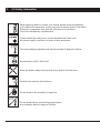
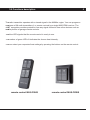
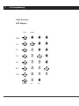
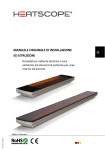
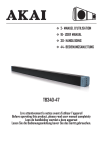
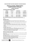
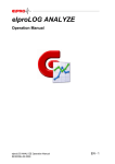
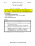
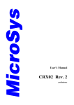
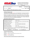
User manual for HEATSTRIP™ radio receiver
Remote control systems
for
This installation and user
manual encompasses
information about the
following products:
MHS-FBM
MHS-FBHS
MHS-FBWS
MHS-ESM
D
Exclusively engineered and made in Germany
1
Table of contents
1.0 Use
page 2
2.0 Safety Information
page 2
3.0 Functionality description
page 4
4.0 Assembly
page 5
5.0 Programming
page 7
6.0 Operation
page 9
7.0 Connecting element MHS-ESM
page 10
8.0 Technical Information
back page
Delivery:
Radio receiver module
Power connector (already installed on the machine)
Assembly and user manual
1 piece
2 pieces
1 piece
and optionally
Hand held remote control
or
Wall-mounted remote control
1 piece
1 piece
1.0 Use – 2.0 Safety information
Thank you for choosing HEATSTRIP™, the black light infrared electric heater. This
user manual will guide you through the connection and programming of the radio
receiver MHS-FBM. These instructions are an addition and valid only in combination with the general HEATSTRIP™ manual, chapter 4.7.
Our remote controls are powered by the EnOcean technology, which enables them
to run battery free. When pressing the button of the remote control, the system
harnesses the physical pressure of your thumb onto the remote control and
converts it into an electro-magnetic signal that is picked up by our MHS-FBM
receiver.
Electronic smog and radio signals
Many people are worried about the possible consequences for their health of the
electronic smog created by the countless electrical fields due to the many wireless
devices we are surrounded by. Manufacturers hence worry about possible claims
for damages based on such health related harm. Nevertheless, the need for
wireless devices keeps increasing quickly. Therefore, we had the standard
intensity of the electro-magnetic fields created by our radio receivers measured by
ECOLOG under in situ usage conditions (ECOLOG is the German Institute for
Socio-Ecological Research and Education).
What are the results?
1. The Enocean Radio system emits one hundred times less intensive
high-frequency fields than conventional light switches (the latter’s high-frequency
fields are produced through the characteristic sparkling switching process).
2. The intensity of the quick high-frequency emissions of the EnOcean radio switch
are up to 10,000 times fewer than the permanent high-frequency emissions of the
mobile phone network stations in residential homes.
3. Thanks to the lack of cables and switches, our radio system works without
interefering with low-frequency electro-magnetic emissions.
4. This radio system is used in schools, hospitals, and even in houses built
according to Feng Shui principles.
2
3
2.0 Safety information
When planning where to locate your device, please check accessibility
to the different components as you may have to access them in the future.
Electronic components may also fail and have to be replaced.
Only to be installed by a professional.
Please check the cable cross -section between the heater and
the power supply is sufficient in terms of size and power.
The surrounding temperature should not exceed 40 degrees Celsius.
Exclusively for 230V / 50 Hz AC .
Keep the devise away from physical chocs and do not use force.
Protect from wetness and moisture.
Do not install in the proximity of open fire.
Do not install where surrounding temperatures
are constantly below 0 degrees Celsius.
Hinweise
zum Handfunksender/Funksender
für Wandmontage
3.0 Functions
description
The radio transmitter operates with a closed signal in the 866Mhz region. You can program a
maximum of 28 radio transmitters (i.e. remote controls) per single MHS-FBM receiver. The
32BIT encryption provides protection from any signal confusion from other devices such as
mobile phones or garage remote controls.
The blue LED signals that the remote control is ready to use.
The number of green LEDs lit indicates the chosen heat intensity.
You can select your requested heat settings by pressing the buttons on the remote control.
remote control MHS-FBHS
remote control MHS-FBWS
4
5
4.0 Assembly
Caution: antenna
is not removable.
5
1
2
6
3
4
Programming button
Legend:
1x MHS Heatstrip (5)
1x MHS-FBM (6)
2x Sockets (1)
2x Bolts (2)
1x Power connector (3)
2x Screws (4)
6
Remove the lateral screw cap in order to reach the programming button. Once the
programming is complete, please put the screw cap back in place.
Caution: When synching the Heatstrip Heater with the MHS-FBM receiver, please make
sure to place the remote control in a perimeter less than 5 meters away from the
Heatstrip Receiver. When the programming mode is on, make sure to maintain the
power supply to the receiver as a potential power cut can damage the device.
Fix the sockets (1) on the bolts (2). Screw the bolts into the Heatstrip heater (5). Plug the
connector (3) to the heater and push the two elements together until you feel a click. Fix
the MHS-FBM receiver or the connecting element MHS-ESM (6) until it clicks with the
connector. Place the screws (4) in and turn tight to secure the fixing.
7
5.0 Programming
Light Scheme
LED Display
blue
green
0,5 h
1h
2h
3h
4h
8h
12 h
blinks
on
off
8
Remote control programming
- Press briefly the lateral button on the MHS-FBM receiver (less than 1 sec).
Three green LEDs + one blue LED flash two times per second.
- On the remote control, press and release the button you wish to control the device with.
Then the LEDs blink for 2 seconds while the radio button is being synchronized with
the MHS-FBM receiver
To terminate the programming mode, wait for 30 seconds or press the programming button.
The chosen switch is saved.
Remote control resetting
- Press briefly and release the lateral programming button on the MHS-FBM receiver
(less than 1 sec). Three green LEDs + one blue LED flash two times per second.
- On the remote control, press and release button to reset.
The LEDs flash 10 times, then the button is reset.
- To terminate the reset mode, wait for 30 seconds or press the programming button.
Setting of maximum heating duration
- Press and hold the lateral button for more than 2 seconds.
- After 2 seconds the blue LED will briefly flash three times:
the blue LED flashes every second,
the green LEDs show the set time.
- Each short press & release of the lateral button on the receiver will increment
the heating duration according to the built-in Time-Code (see below).
- The heating duration can also be changed by pressing the button that has been
previously programmed.
- After 30 seconds following the last press & release, the programming will end and
the chosen Time-Code set is saved.
Time-Code
Can be set from minimum 30 minutes to maximum 12 hours.
7 settings to choose from: 0.5, 1, 2, 3, 4, 8, 12 hours.
9
6.0 Operation
Standby operation:
heating off
blue LED lit
ON
press the ON button
heat output is set up on "power 3" (full power")
press the ON button again
Remote to “Power 0” (OFF)
Heat output
settings
press the OFF button
remote to “Power 2”
2 green LEDs turn on
press in OFF button again
remote to “Power 1”
1 green LED turns on
press in OFF button again
remote to “Power 0” (OFF)
All 3 green LEDs turn on
Standby operation, heating off – blue LED lit
Party mode
The “Party Mode” has a preset heating duration of 4 hours
running on maximum heat supply, regardless of the Time-Code
set (see section “Setting of maximum heating duration” above).
To launch the
“Party Mode”:
Press and hold the ON button for more than 6 seconds. The heater
is set on maximum heat and will switch off automatically after 4
hours. The green and blue LEDs are lit.
General OFF
Press and hold the OFF button for more than 6 seconds. The
heater turns off regardless of the current heating setting. The blue
LED displays the standby mode.
Test operation
without transmitter
(to check the functionality of the receiver module without using the
transmitter)
Press the lateral button on the receiver for more than 10 seconds
-> the heater turns on, 2 LEDs are lit, 80% power.
Press the programing buttons again for for more than 10 seconds,
the heater turns off.
If not, the device is automatically turned off after 2 hours. The blue
standby LED turns on.
7.0 Connecting element
The connecting element serves as a stylish cable connection for your Heatstrip, hiding
the power cable at the backside of the device - instead of it being visible at the front side.
Install the connecting element after point 4.0 in this user manual.
It is not possible to further program or set this element.
10
8.0 Technical data
RoHS compliant
Operating voltage
Wattages
Heat output
Warming up time
Measurements
Power cable
Cable length
Compatability
Transmission range
Transmitter
Performance
Transmission duration
Security
Humidity
Temperature range
Storage temperature
Shutdown
User Manual 2.1 | Valid from 11.11.2011
WEEE-Reg.-Nr. DE 45650441
MHS GmbH
Munich Home Systems
Kramergasse 32
D- 82054 Sauerlach b. München
Tel.: +49-(0)8104-64709-0
Fax: +49-(0)8104-64709-9
[email protected]
www.heatstrip.de
230 V / 50 Hz
maximum 3200 W
3 setting
approx. 10 to 15 minutes,
depending on the weather
(temperature outside,
wind)
circa 170 x 90 x 65mm
EUR or IK plugs
1.5m, 3 x 1.5mm sq
up to max. 28 transmitters
approx. up to 100m free
868,3 MHz frequency
maximum 10 mW
approx. 25ms
32 Bit encryption with up
to 3 telegrams
maximum 85%
from 0ºC to +40ºC
from -30ºC to +65ºC
as a built-in factory setting,
the receiver automatically
shuts down after 12 hours
of continuous use