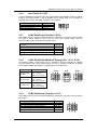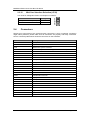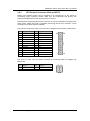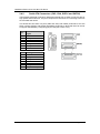
1
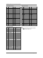
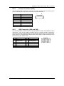
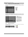
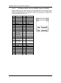
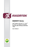
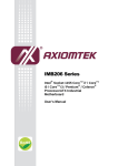
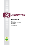
MANO872 Series ® Intel Socket 1155 CoreTM i7 / CoreTM ® i5 / CoreTM i3 / Celeron Processor All-In-One Mini ITX Board with DP / DVI-I / LVDS User’s Manual Disclaimers This manual has been carefully checked and believed to contain accurate information. Axiomtek Co., Ltd. assumes no responsibility for any infringements of patents or any third party’s rights, and any liability arising from such use. Axiomtek does not warrant or assume any legal liability or responsibility for the accuracy, completeness or usefulness of any information in this document. Axiomtek does not make any commitment to update the information in this manual. Axiomtek reserves the right to change or revise this document and/or product at any time without notice. No part of this document may be reproduced, stored in a retrieval system, or transmitted, in any form or by any means, electronic, mechanical, photocopying, recording, or otherwise, without the prior written permission of Axiomtek Co., Ltd. CAUTION If you replace wrong batteries, it causes the danger of explosion. It is recommended by the manufacturer that you follow the manufacturer’s instructions to only replace the same or equivalent type of battery, and dispose of used ones. Copyright 2013 Axiomtek Co., Ltd. All Rights Reserved August 2013, Version A2 Printed in Taiwan ii ESD Precautions Computer boards have integrated circuits sensitive to static electricity. To prevent chipsets from electrostatic discharge damage, please take care of the following jobs with precautions: Do not remove boards or integrated circuits from their anti-static packaging until you are ready to install them. Before holding the board or integrated circuit, touch an unpainted portion of the system unit chassis for a few seconds. It discharges static electricity from your body. Wear a wrist-grounding strap, available from most electronic component stores, when handling boards and components. Trademarks Acknowledgments Axiomtek is a trademark of Axiomtek Co., Ltd. ® Windows is a trademark of Microsoft Corporation. AMI is a trademark of American Megatrend Inc. IBM, PC/AT, PS/2, VGA are trademarks of International Business Machines Corporation. ® TM Intel Core i7 / Core TM i5 / Core TM ® i3 / Celeron are trademarks of Intel Corporation. Winbond is a trademark of Winbond Electronics Corp. Realtek is a trademark of Realtek Semi-Conductor Co., Ltd. Other brand names and trademarks are the properties and registered brands of their respective owners. iii Table of Contents Disclaimers ..................................................................................................... ii ESD Precautions ........................................................................................... iii Chapter 1 Introduction ............................................. 1 1.1 Features ............................................................................................... 1 1.2 Specifications ...................................................................................... 2 1.3 Utilities Supported .............................................................................. 3 Chapter 2 Board and Pin Assignments .................... 5 2.1 Board Dimensions and Fixing Holes ................................................. 5 2.2 Board Layout ....................................................................................... 7 2.3 Jumper Settings .................................................................................. 9 2.3.1 2.3.2 2.3.3 2.3.4 2.3.5 2.3.6 2.3.7 2.3.8 2.3.9 2.3.10 2.4 Connectors ........................................................................................ 12 2.4.1 2.4.2 2.4.3 2.4.4 2.4.5 2.4.6 2.4.7 2.4.8 2.4.9 2.4.10 2.4.11 2.4.12 2.4.13 2.4.14 2.4.15 iv Restore BIOS Optimal Defaults (JP1) ....................................................... 10 LVDS Voltage Selection (JP2 and JP3) .................................................... 10 USB Port 4 and 5 Power Selection (JP4) ................................................. 10 SATA/SATADOM Selection (JP5) .............................................................. 10 LVDS Backlight Control Mode Setting (JP7) ............................................. 10 Auto Power On (JP8) ................................................................................. 11 COM1 Data/Power Selection (JP10) .......................................................... 11 COM1 RS-232/422/485 Mode Setting (JP11, JP12, JP14) ....................... 11 COM3 Data/Power Selection (JP13) .......................................................... 11 Mini Card Interface Selection (JP16) ........................................................ 12 ATX Power Connectors (CN2 and ATX1).................................................. 13 Serial ATA Connectors (CN3, CN4, SATA1 and SATA2) ........................... 14 LVDS Connector (CN6) ............................................................................. 15 Inverter Connectors (CN7) ........................................................................ 17 USB Connectors (CN8 and CN9).............................................................. 17 LAN and USB Connectors (CN10 and CN11) ........................................... 18 DVI-I Connector (CN12) ............................................................................ 19 COM Connectors (CN13, CN14 and CN15) ............................................. 20 HD Audio Jack (CN16) .............................................................................. 20 Internal Audio Connector (CN17) .............................................................. 21 Display Port Connector (CN18) ................................................................. 21 PCI-Express Mini Card and mSATA Connector (SCN2) ........................... 22 FAN Connectors (FAN1 and FAN2) .......................................................... 23 Front Panel Connector (JP6) .................................................................... 23 Digital I/O Connector (JP9) ....................................................................... 24 Chapter 3 Hardware Installation ........................... 25 3.1 Installing the Processor .................................................................... 25 3.2 Installing the Memory ....................................................................... 31 Chapter 4 Hardware Description ........................... 33 4.1 Microprocessors ............................................................................... 33 4.2 BIOS ................................................................................................... 33 4.3 System Memory ................................................................................. 33 4.4 I/O Port Address Map ........................................................................ 34 4.5 Interrupt Controller (IRQ) Map ......................................................... 36 4.6 Memory Map ...................................................................................... 37 Chapter 5 AMI BIOS Setup Utility .......................... 39 5.1 Starting ............................................................................................... 39 5.2 Navigation Keys ................................................................................ 39 5.3 Main Menu.......................................................................................... 40 5.4 Advanced Menu ................................................................................. 41 5.5 Chipset Menu ..................................................................................... 50 5.6 Boot Menu.......................................................................................... 54 5.7 Security Menu .................................................................................... 55 5.8 Save & Exit Menu .............................................................................. 56 Appendix A Watchdog Timer ................................... 59 About Watchdog Timer ................................................................................ 59 How to Use Watchdog Timer....................................................................... 59 Appendix B Digital I/O ............................................. 61 Using Digital Output Function .................................................................... 61 Using Digital Input Function ....................................................................... 61 Appendix C Configuring SATA for RAID .................. 63 Configuring SATA Hard Drive(s) for RAID Function.................................. 63 Appendix D Intel® iAMT Settings ............................ 73 Entering MEBx ............................................................................................. 73 Set and Change Password .......................................................................... 74 Intel® iAMT Web Console ............................................................................ 76 v This page is intentionally left blank. vi MANO872 Series All-In-One Mini ITX Board Chapter 1 Introduction ® TM ® TM The MANO872 is a Mini ITX board with LGA1155 socket for Intel Core i7 / Intel Core i5 / ® TM ® ® Intel Core i3 / Intel Celeron (G6950) desktop processor with 22nm technology. The board ® integrates Intel Q77 chipset that delivers outstanding system performance through high-bandwidth interfaces, multiple I/O functions for interactive applications and various embedded computing solutions. There are two 204-pin DDR3 SO-DIMM sockets for dual channel DDR3 1333/1600MHz memory with maximum capacity up to 16GB; assuming dual channel mode of two 8GB double-sided unbuffered, non-ECC SO-DIMM memory configuration. The board also features Gigabit Ethernet, two SATA 3.0 ports (support SATA RAID 0/1/5/10 by Q77) at maximum transfer rate up to 6Gb/s, two SATA 2.0 ports at maximum transfer rate up to 3Gb/s, four USB 3.0 and four USB 2.0 high speed compliant ports that can achieve the best stability and reliability for industrial applications. 1.1 Features rd ® TM ® LGA1155 socket 3 Generation Intel Core i7 / i5 / i3 / Celeron processors 2 DDR3 1333/1600MHz up to 16GB PCI-Express Gen. 3 supported 2 SATA-600 with RAID 0, 1, 5 and 10 supported 2 SATA-300 with 1 SATADOM supported 4 USB 3.0 supported iAMT 8.0 supported TPM 1.2 supported Triple view display Introduction 1 MANO872 Series All-In-One Mini ITX Board 1.2 Specifications CPU ® Intel ® Intel ® Intel ® Intel TM Core i7 desktop processor. TM Core i5 desktop processor. TM Core i3 desktop processor. Celeron® desktop processors. System Chipset ® Intel Q77. CPU Socket LGA1155. DRAM Transfer Rate 1333/1600MHz. BIOS AMI BIOS via SPI interface with socket. System Memory Two 204-pin unbuffered DDR3 SO-DIMM sockets. Maximum up to 16GB DDR3 1333/1600MHz memory with two SO-DIMMs using 8GB memory technology. Onboard Multi I/O Controller: Nuvoton NCT6627UD. Serial ports: Three RS-232 ports (COM2/3/4) and one RS-232/422/485 port (COM1). SATADOM (Optional) One SATADOM supported; co-layout with a SATA-300 socket (according to SATA 2.0 signal). Serial ATA Supports SATA 3.0 and SATA 2.0. Two SATA 3.0 ports (6Gb/s performance) with SATA RAID 0/1/5/10 by Q77 and two SATA 2.0 ports (3Gb/s performance). USB Interface Four USB 3.0 ports with fuse protection. Four USB 2.0 ports with fuse protection. Display One Display Port. One LVDS 24-bit dual channel. One DVI-I. Note: Due to Intel design limitation and BIOS default option, under DOS only VGA display is supported. 2 Introduction MANO872 Series All-In-One Mini ITX Board Watchdog Timer 1~255 seconds; up to 256 levels. Expansion Interface One PCI-Express x16 slot. Ethernet ® LAN1 – Intel 82579LM supports 10/100/1000Mbps. ® LAN2 – Intel 82583V supports 10/100/1000Mbps. Audio HD audio compliant (with line/speaker-out and MIC-in) via ALC662. Internal audio feature for speaker-out via wafer connector. Power Management ACPI (Advanced Configuration and Power Interface). Form Factor Mini ITX form factor. Note: 1.3 All specifications and images are subject to change without notice. Utilities Supported Chipset driver Ethernet driver Graphics driver Audio driver Introduction 3 MANO872 Series All-In-One Mini ITX Board This page is intentionally left blank. 4 Introduction MANO872 Series All-In-One Mini ITX Board Chapter 2 Board and Pin Assignments 2.1 Board Dimensions and Fixing Holes Top Side Board and Pin Assignments 5 MANO872 Series All-In-One Mini ITX Board Bottom Side 6 Board and Pin Assignments MANO872 Series All-In-One Mini ITX Board 2.2 Board Layout Top Side I/O Bracket Board and Pin Assignments 7 MANO872 Series All-In-One Mini ITX Board Bottom Side 8 Board and Pin Assignments MANO872 Series All-In-One Mini ITX Board 2.3 Jumper Settings Jumper is a small component consisting of jumper clip and jumper pins. Install jumper clip on 2 jumper pins to close. And remove jumper clip from 2 jumper pins to open. The following illustration shows how to set up jumper. Before applying power to MANO872 Series, please make sure all of the jumpers are in factory default position. Below you can find a summary table and onboard default settings. Jumper Description Setting JP1 Restore BIOS Optimal Defaults Default: Normal Operation 1-2 close JP2 (Optional) LVDS Voltage Selection All open JP3 LVDS Voltage Selection Default: +3.3V 1-2 close JP4 USB Port 4 and 5 Power Selection Default: Standby Power +5V 1-2 close JP5 SATA/SATADOM Selection Default: SATA 2-3 close JP7 LVDS Backlight Control Mode Setting Default: PWM Mode 1-2 close JP8 Auto Power On Default: Disable 1-2 close JP10 COM1 Data/Power Selection Default: RS-232 Data JP11 JP12 JP14 CN15A Pin 1: DCD 3-5 close CN15A Pin 9: RI 4-6 close 3-5, 4-6 close COM1 RS-232/422/485 Mode Setting Default: RS-232 JP13 COM3 Data/Power Selection Default: RS-232 Data JP16 Mini Card Interface Selection Default: PCI-Express Interface Board and Pin Assignments 1-2 close 3-5, 4-6 close CN13 Pin 1: DCD 3-5 close CN13 Pin 8: RI 4-6 close 1-2 Close 9 MANO872 Series All-In-One Mini ITX Board 2.3.1 Restore BIOS Optimal Defaults (JP1) Put jumper clip to pin 2-3 for a few seconds then move it back to pin 1-2. Doing this procedure can restore BIOS optimal defaults. Function Setting Normal operation (Default) Restore BIOS optimal defaults 1-2 close 2-3 close 2.3.2 LVDS Voltage Selection (JP2 and JP3) The board supports voltage selection for flat panel displays. Use JP3 to set LVDS connector (CN6) pin 1~6 VCCM to +3.3V or +5V voltage level. Use JP2 (optional) to set LVDS connector (CN6) pin 1~6 VCCM to +12V voltage level. To prevent hardware damage, before connecting please make sure that the input voltage of LVDS flat panel is correct. Function JP3 Setting +3.3V level (Default) +5V level 1-2 close 2-3 close Function JP2 Setting +12V level (Optional) 1-2 close 2.3.3 JP2 JP3 USB Port 4 and 5 Power Selection (JP4) Use JP4 for setting USB power signal on connector CN9 to standby power or system power. Function Setting Standby power +5V level (Default) System power +5V level 1-2 close 2-3 close 2.3.4 SATA/SATADOM Selection (JP5) Use JP5 for enabling connector CN4 to support SATA or SATADOM. Function Setting SATADOM SATA (Default) 1-2 close 2-3 close 2.3.5 LVDS Backlight Control Mode Setting (JP7) The JP7 is enabled to select PWM or DC control mode for inverter connector (CN7). These two control modes are for adjusting LVDS brightness. 10 Function Setting PWM mode (Default) DC mode 1-2 close 3-4 close Board and Pin Assignments MANO872 Series All-In-One Mini ITX Board 2.3.6 Auto Power On (JP8) If JP8 is enabled for AC power input, the system will be automatically power on without pressing soft power button. If JP8 is disabled for AC power input, it is necessary to manually press soft power button to power on the system. Function Setting Disable auto power on (Default) Enable auto power on 1-2 close 2-3 close 2.3.7 COM1 Data/Power Selection (JP10) The COM1 port has +5V level power capability on DCD and +12V level on RI by setting this jumper. When COM1 is set to +5V or +12V level, please make sure the communication mode is RS-232 (see section 2.3.8). Function Setting Power: Set CN15A pin 1 to +5V level Data: Set CN15A pin 1 to DCD (Default) Power: Set CN15A pin 9 to +12V level Data: Set CN15A pin 9 to RI (Default) 1-3 close 3-5 close 2-4 close 4-6 close 2.3.8 COM1 RS-232/422/485 Mode Setting (JP11, JP12, JP14) Use these jumpers to set COM1 port to operate as RS-232, RS-422 or RS-485 communication mode. When these jumpers are set to operate as RS-422 or RS485 mode, please make sure COM1 is on data mode (see section 2.3.7) Function Setting RS-232 mode (Default) RS-422 mode RS-485 mode 2.3.9 JP11 3-5, 4-6 close JP12 1-2 close JP14 3-5, 4-6 close JP11 1-3, 2-4 close JP12 3-4 close JP14 1-3, 2-4 close JP11 1-3, 2-4 close JP12 5-6 close JP14 1-3, 2-4 close JP11 JP12 JP14 COM3 Data/Power Selection (JP13) The COM3 port has +5V level power capability on DCD and +12V level on RI by setting this jumper. Function Setting Power: Set CN13 pin 1 to +5V level Data: Set CN13 pin 1 to DCD (Default) Power: Set CN13 pin 8 to +12V level Data: Set CN13 pin 8 to RI (Default) 1-3 close 3-5 close 2-4 close 4-6 close Board and Pin Assignments 11 MANO872 Series All-In-One Mini ITX Board 2.3.10 Mini Card Interface Selection (JP16) Use JP16 for setting Mini Card to PCI-Express or mSATA . Function Setting PCI-Express Interface (Default) mSATA Interface 1-2 close 2-3 close 2.4 Connectors Signals go to other parts of the system through connectors. Loose or improper connection might cause problems, please make sure all connectors are properly and firmly connected. Here is a summary table which shows all connectors on the hardware. Connector Description CN1 PCI-Express x16 Slot CN2 24-pin ATX Power Connector CN3 Serial ATA 2.0 port 2 Connector CN4 Serial ATA 2.0 port 3 Connector (Optional for SATADOM) CN6 LVDS Connector CN7 Inverter Connector CN8 USB 2.0 Port 6 and 7 Connector CN9 USB 2.0 Port 4 and 5 Connector CN10 LAN1 (WG82579LM), USB 3.0 Port 2 and 3 Connector CN11 LAN2 (WG82583V), USB 3.0 Port 0 and 1 Connector CN12 DVI-I Connector CN13 COM3 Connector CN14 COM4 Connector CN15 COM1 and COM2 Connector CN16 HD Audio Jack CN17 Internal Audio Connector CN18 Display Port Connector SCN2 PCI-Express Mini Card and mSATA Connector ATX1 4-pin +12V ATX Power Connector FAN1 CPU Fan Connector FAN2 System Fan Connector JP6 Front Panel Connector JP9 Digital I/O Connector SATA1~2 Serial ATA 3.0 port 0 and 1 Connectors DIMM1~2 DDRIII SO-DIMM Connectors 12 Board and Pin Assignments MANO872 Series All-In-One Mini ITX Board 2.4.1 ATX Power Connectors (CN2 and ATX1) Steady and sufficient power can be supplied to all components on the board by connecting power connector. Please make sure all components and devices are properly installed before connecting the power connector. External power supply plug fits into this connector in only one orientation. Properly press down power supply plug until it completely and firmly fits into this connector. Loose connection may cause system instability. The CN2 is a 24-pin ATX power connector. Its pin assignments are given in table below. Pin Signal Pin Signal 1 2 3 4 5 6 7 8 9 10 11 12 3.3V 3.3V GND +5V GND +5V GND PWR OK 5VSB +12V +12V 3.3V 13 14 15 16 17 18 19 20 21 22 23 24 3.3V -12V GND PS_ON GND GND GND -5V +5V +5V +5V GND The ATX1 is a 4-pin +12V ATX power connector for connecting CPU core voltage, see table below. Pin Signal Pin Signal 1 2 GND GND 3 4 +12V +12V Board and Pin Assignments 13 MANO872 Series All-In-One Mini ITX Board 2.4.2 Serial ATA Connectors (CN3, CN4, SATA1 and SATA2) These Serial Advanced Technology Attachment (Serial ATA or SATA) connectors are for high-speed SATA interfaces. They are computer bus interfaces for connecting to devices such as hard disk drives. This board has two SATA 2.0 ports (CN3 and CN4) with 3Gb/s performance and two SATA 3.0 ports (SATA1 and SATA2) with 6Gb/s performance. Note that CN4 can be set to support SATADOM by configuring jumper JP5 (see section 2.3.4). 14 Pin CN3/SATA1/SATA2 Signal 1 2 3 4 5 6 7 GND SATA_TX+ SATA_TXGND SATA_RXSATA_RX+ GND Pin CN4 Signal 1 2 3 4 5 6 7 GND SATA_TX+ SATA_TXGND SATA_RXSATA_RX+ GND(DEFAULT)/+5V Board and Pin Assignments MANO872 Series All-In-One Mini ITX Board 2.4.3 LVDS Connector (CN6) This board has a 40-pin connector (CN6) for LVDS LCD interface. It is strongly recommended to use the matching JST SHDR-40VS-B 40-pin connector for LVDS interface. Pin 1~6 VCCM can be set to +3.3V, +5V or +12V level by JP2 and JP3 (see section 2.3.2). 18-bit single channel Pin Signal Pin Signal 1 3 5 7 9 11 13 15 17 19 21 23 25 27 29 31 33 35 37 39 VCCM VCCM VCCM EDID DATA GND N.C. N.C. GND N.C. N.C. GND Channel A D0Channel A D0+ GND Channel A D1Channel A D1+ GND Channel A D2Channel A D2+ GND 2 4 6 8 10 12 14 16 18 20 22 24 26 28 30 32 34 36 38 40 VCCM VCCM VCCM EDID CLK GND N.C. N.C. GND N.C. N.C. GND N.C. N.C. GND N.C. N.C. GND Channel A CLKChannel A CLK+ GND Board and Pin Assignments 15 MANO872 Series All-In-One Mini ITX Board 24-bit single channel 18-bit dual channel Pin Signal Pin Signal Pin Signal Pin Signal 1 3 5 7 9 11 13 15 17 19 21 23 25 27 29 31 33 35 37 39 2 4 6 8 10 12 14 16 18 20 22 24 26 28 30 32 34 36 38 40 1 3 5 7 9 11 13 15 17 19 21 23 25 27 29 31 33 35 37 39 2 4 6 8 10 12 14 16 18 20 22 24 26 28 30 32 34 36 38 40 VCCM VCCM VCCM EDID DATA GND N.C. N.C. GND N.C. N.C. GND Channel A D0Channel A D0+ GND Channel A D1Channel A D1+ GND Channel A D2Channel A D2+ GND VCCM VCCM VCCM EDID CLK GND N.C. N.C. GND N.C. N.C. GND N.C. N.C. GND Channel A D3Channel A D3+ GND Channel A CLKChannel A CLK+ GND VCCM VCCM VCCM EDID DATA GND N.C. N.C. GND Channel B CLKChannel B CLK+ GND Channel A D0Channel A D0+ GND Channel A D1Channel A D1+ GND Channel A D2Channel A D2+ GND VCCM VCCM VCCM EDID CLK GND Channel B D0Channel B D0+ GND Channel B D1Channel B D1+ GND Channel B D2Channel B D2+ GND N.C. N.C. GND Channel A CLKChannel A CLK+ GND 24-bit dual channel Pin Signal Pin Signal 1 VCCM 2 VCCM 3 VCCM 4 VCCM 5 VCCM 6 7 EDID DATA 8 VCCM EDID CLK 9 GND 10 GND 11 Channel B D3- 12 Channel B D0- 13 Channel B D3+ 14 Channel B D0+ 15 GND 16 GND 17 Channel B CLK- 18 Channel B D1- 19 Channel B CLK+ 20 Channel B D1+ 21 GND 22 GND 23 Channel A D0- 24 Channel B D2- 25 Channel A D0+ 26 Channel B D2+ 27 GND 28 GND 29 Channel A D1- 30 Channel A D3- 31 Channel A D1+ 32 Channel A D3+ 33 GND 34 GND 35 Channel A D2- 36 Channel A CLK- 37 Channel A D2+ 38 Channel A CLK+ 39 GND 40 GND 16 Note: See section 5.5 for LVDS resolution setting in BIOS menu. Board and Pin Assignments MANO872 Series All-In-One Mini ITX Board 2.4.4 Inverter Connectors (CN7) The CN7 is DF13-8P-1.25V 8-pin connector for inverter. We strongly recommend you to use the matching DF13-8S-1.25C connector to avoid malfunction. 1 Pin Signal 1 2 3 4 5 6 7 8 VBL1 (+12V level) VBL1 (+12V level) VBL2 (+5V level) VBL_ENABLE GND GND GND LVDS_BRICTL 2.4.5 8 USB Connectors (CN8 and CN9) The CN8 and CN9 are USB connectors carrying USB port 6 and 7 and USB port 4 and 5, respectively. They are for installing versatile USB 2.0 compliant interface peripherals. These connectors are designed with +5V level standby power which can provide power when system is in suspend mode. Note that the power signal on CN9 can also be set to system power (see section 2.3.3). Pin 1 3 5 7 9 Signal USB VCC (+5V level standby power) USB DXUSB DX+ GND GND Board and Pin Assignments Pin 2 4 6 8 10 Signal CN8/CN9 USB VCC (+5V level standby power) USB DYUSB DY+ GND GND 17 MANO872 Series All-In-One Mini ITX Board 2.4.6 LAN and USB Connectors (CN10 and CN11) The board comes with two high performance plug and play ethernet interfaces (RJ-45) which are fully compliant with the IEEE 802.3 standard. Connection can be established by plugging one end of the ethernet cable into this RJ-45 connector and the other end to a 1000/100/10-Base-T hub. The Universal Serial Bus (compliant with USB 3.0 (5Gb/s)) connectors on the rear I/O are for installing USB peripherals such as keyboard, mouse, scanner, etc. Note that the CN10 carries LAN1, USB 3.0 port 2 and 3 signals while CN11 carries LAN2, USB 3.0 port 0 and 1 signals. Pin L1 L2 L3 L4 Pin LAN1 Signal (WG82579LM) MDI2+ MDI2MDI3+ MDI3- B MDI0+ L5 MDI0L6 MDI1+ L7 MDI1L8 100 LAN LED (Green)/ 1000 LAN LED (Orange) Active LED Pin USB Signal USB Signal A 1 2 3 4 5 6 7 8 9 18 LAN1 Signal (WG82579LM) USB_VCC (+5V level standby power) USB_Data2USB_Data2+ GND SSRX2SSRX2+ GND SSTX2SSTX2+ Pin 10 11 12 13 14 15 16 17 18 CN10 USB_VCC (+5V level standby power) USB_Data3USB_Data3+ GND SSRX3SSRX3+ GND SSTX3SSTX3+ Board and Pin Assignments MANO872 Series All-In-One Mini ITX Board Pin L1 L2 L3 L4 LAN2 Signal (WG82583V) Pin LAN2 Signal (WG82583V) MDI2+ MDI2MDI3+ MDI3- B MDI0+ L5 MDI0L6 MDI1+ L7 MDI1L8 100 LAN LED (Green)/ 1000 LAN LED (Orange) Active LED Pin USB Signal USB Signal A 1 2 3 4 5 6 7 8 9 2.4.7 Pin USB_VCC (+5V level standby power) USB_Data0USB_Data0+ GND SSRX0SSRX0+ GND SSTX0SSTX0+ 10 11 12 13 14 15 16 17 18 CN11 USB_VCC (+5V level standby power) USB_Data1USB_Data1+ GND SSRX1SSRX1+ GND SSTX1SSTX1+ DVI-I Connector (CN12) The board comes with a high rise DVI-I (Digital Video Interface – Integrated) interface providing transmission of fast and high quality video signal between source device (e.g. graphic card) and display device (e.g. monitor). The DVI-I interface supports both digital and analog. Pin Signal Pin Signal 1 3 5 7 9 11 13 15 17 19 21 23 C1 C3 C5 TX2Ground NC DVI_SPD DATA TX1Ground NC Ground TX0Ground NC TXC+ CRT-RED CRT-BLUE VGAGND 2 4 6 8 10 12 14 16 18 20 22 24 C2 C4 TX2+ NC DVI_SPD_CLK CRT-VSYNC TX1+ NC VGAVCC FPDETECT TX0+ NC Ground TXCCRT-GREEN CRT-HSYNC Board and Pin Assignments 19 MANO872 Series All-In-One Mini ITX Board 2.4.8 COM Connectors (CN13, CN14 and CN15) The COM3 and COM4 interfaces are available through CN13 and CN14, respectively. Each of these connectors is a 2x5 pin 2.0 pitch box header, see table below for its pin assignments. Pin Signal 1 2 3 4 5 6 7 8 9 10 Data Carrier Detect (DCD) Data Set Ready (DSR) Receive Data (RXD) Request to Send (RTS) Transmit Data (TXD) Clear to Send (CTS) Data Terminal Ready (DTR) Ring Indicator (RI) Ground (GND) NC CN13/CN14 The CN15 is a double-deck DB-9 connector. The upper connector (CN15A) is for COM1 and the lower connector (CN15B) is for COM2. Note that the connectors (CN13 and CN15A) come with power capability on DCD and RI pins by setting jumpers (see section 2.3.7 and 2.3.9). Pin Pin Signal 1 2 3 4 5 6 7 8 9 10 11 12 13 14 15 16 17 18 Data Carrier Detect (DCD) Receive Data (RXD) Transmit Data (TXD) Data Terminal Ready (DTR) Ground (GND) Data Set Ready (DSR) Request to Send (RTS) Clear to Send (CTS) Ring Indicator (RI) 2.4.9 CN15A CN15B HD Audio Jack (CN16) The board provides a HD audio jack on the rear I/O. Install audio driver, and then attach audio devices to CN16. 20 Pin Color Signal Green Pink Line-out MIC-in Board and Pin Assignments MANO872 Series All-In-One Mini ITX Board 2.4.10 Internal Audio Connector (CN17) CN17 is an internal audio connector for line-out and microphone. Pin Signal 1 2 3 4 5 Lineout-L GND Lineout-R GND MIC-in 2.4.11 1 5 Display Port Connector (CN18) Display Port is a digital display interface standard which is available through connector CN18. Pin Signal 1 2 3 4 5 6 7 8 9 10 11 12 13 14 15 16 17 18 19 20 LANE 0 GND LANE 0# LANE 1 GND LANE 1# LANE 2 GND LANE 2# LANE 3 GND LANE 3# HDMI_DET GND AUX CH GND AUX CH# Hot Plug Detect GND DP_PWR(3.3V) Board and Pin Assignments 19 18 1 2 21 MANO872 Series All-In-One Mini ITX Board 2.4.12 PCI-Express Mini Card and mSATA Connector (SCN2) SCN2 (soldered on the bottom side) is a PCI-Express Mini Card connector which supports a PCI-Express x1 link, a SATA link and a USB 2.0 link. A PCI-Express Mini Card can be applied to either PCI-Express or USB 2.0 and SATA also. It complies with PCI-Express Mini Card spec v1.2. Pin Signal Pin Signal 1 3 5 7 9 11 13 15 17 19 21 WAKE# No use No use CLKREQ# GND REFCLKREFCLK+ GND No use No use GND PE_RXN/ SATA_RXP PE_RXP/ SATA_RXN GND GND PE_TXN3/ SATA_TXN PE_TXP3/ SATA_TXP GND GND +3.3VSB +3.3VSB GND No use No use No use No use 2 4 6 8 10 12 14 16 18 20 22 24 +3.3VSB GND +1.5V No use No use No use No use No use GND W_DISABLE# PERST# +3.3VSB 26 GND 28 30 32 +1.5V SMB_CLK SMB_DATA 34 GND 36 38 40 42 44 46 48 50 52 USB_D8USB_D8+ GND No use No use No use +1.5V GND +3.3VSB 23 25 27 29 31 33 35 37 39 41 43 45 47 49 51 22 Board and Pin Assignments MANO872 Series All-In-One Mini ITX Board 2.4.13 FAN Connectors (FAN1 and FAN2) Fans are always needed for cooling down CPU and system temperature. The board has two fan connectors. You can find fan speed option(s) at BIOS Setup Utility if either fan is installed. For further information, see BIOS Setup Utility: Advanced\HW Monitor\PC Health Status. CPU fan interface is available through FAN1, see table below. Pin Signal 1 2 3 4 GND +12V level Rotation detection Speed control System fan interface is available through FAN2, see table below. Pin Signal 1 2 3 GND +12V level Rotation detection 2.4.14 Front Panel Connector (JP6) Pin Signal 1 2 3 4 5 6 7 8 9 10 11 12 13 14 PWRLED+ EXT SPKGND Buzzer PWRLEDN.C. N.C. EXT SPK+ PWRSWPWRSW+ HW RSTHW RST+ HDDLEDHDDLED+ Power LED Pin 1 connects anode(+) of LED and pin 5 connects cathode(-) of LED. The power LED lights up when the system is powered on. The pin 3 is defined as GND. External Speaker and Internal Buzzer Pin 2, 4, 6 and 8 connect the case-mounted speaker unit or internal buzzer. While connecting the CPU board to an internal buzzer, please set pin 2 and 4 closed; while connecting to an external speaker, you need to set pins 2 and 4 opened and connect the speaker cable to pin 8(+) and pin 2(-). Board and Pin Assignments 23 MANO872 Series All-In-One Mini ITX Board Power On/Off Button Pin 9 and 10 connect the power button on front panel to the CPU board, which allows users to turn on or off power supply. System Reset Switch Pin 11 and 12 connect the case-mounted reset switch that reboots your computer without turning off the power switch. It is a better way to reboot your system for a longer life of system power supply. HDD Activity LED This connection is linked to hard drive activity LED on the control panel. LED flashes when HDD is being accessed. Pin 13 and 14 connect the hard disk drive to the front panel HDD LED, pin 13 is assigned as cathode(-) and pin 14 is assigned as anode(+). 2.4.15 Digital I/O Connector (JP9) The board is equipped with an 8-channel digital I/O connector that meets requirements for a system customary automation control. The digital I/O can be configured to control cash drawers and sense warning signals from an Uninterrupted Power System (UPS), or perform store security control. You may use software programming to control these digital signals. 24 Pin Signal Pin Signal 1 3 5 7 9 DIO 8 DIO 7 DIO 6 DIO 5 GND 2 4 6 8 10 DIO 1 DIO 2 DIO 3 DIO 4 GND Board and Pin Assignments MANO872 Series All-In-One Mini ITX Board Chapter 3 Hardware Installation ® Before installing the processor, please access Intel website for more detail information of Processor Integration Video (LGA1155): http://www.intel.com/support/tw/processors/sb/CS-030860.htm . 3.1 Installing the Processor The LGA1155 processor socket comes with a cover to protect the processor. Please install the processor into the CPU socket step by step as below: Step1 Opening the socket: Disengage load lever by releasing down and out on the hook. This will clear retention tab. Rotate load lever to open position at approximately 135°. Rotate load plate to open position at approximately 150°. Note: Apply pressure to corner with right-hand thumb when opening or closing load lever otherwise lever will bounce back (as a mouse trap) causing bent contacts. Step2 Removing the socket protective cover: Place thumb against the front edge of the protective cover and rest index finger on the rear grip to maintain control of the cover. Lift the front edge of the protective cover to disengage from the socket. Keep control of the cover by holding the rear grip with index finger. Lift protective cover away from the socket, being careful not to touch the electrical contacts. Hardware Installation 25 MANO872 Series All-In-One Mini ITX Board Note: Vertical removal is NOT recommended, as it requires higher force and can lead to socket contact damage. Caution: Never touch fragile socket contacts to avoid damage and do not touch processor sensitive contacts at any time during installation. Step3 Processor installation: Lift processor package from shipping media by grasping the substrate edges. Scan the processor package gold pads for any presence of foreign material. If necessary, the gold pads can be wiped clean with a soft lint-free cloth and isopropyl alcohol. Locate connection 1 indicator on the processor which aligns with connection 1 indicator chamfer on the socket, and notice processor keying features that line up with posts along socket walls. 26 Hardware Installation MANO872 Series All-In-One Mini ITX Board Grasp the processor with thumb and index finger along the top and bottom edges. (Do not touch the orientation notches.) The socket will have cutouts for your fingers to fit into (see image below). Carefully place the processor into the socket body vertically (see image below). Note: Tilting or roughly shifting it into place can damage socket contacts. Caution: Do not use a vacuum pen for installation. Hardware Installation 27 MANO872 Series All-In-One Mini ITX Board Verify that package is within the socket body and properly connected to orientation keys. Close the socket (see image below): 1. Gently lower the load plate. 2. Make sure load plate's front edge slides under the shoulder screw cap as the lever is lowered. 3. Latch the lever under the top plate's corner tab, being cautious not to damage the motherboard with the tip of the lever. Step4 Fan heatsink handling: 1. 28 Orientate the CPU cooling fan to fixing holes on the board. Hardware Installation MANO872 Series All-In-One Mini ITX Board 2. Screw the CPU cooling fan onto the board. 3. Make sure the CPU fan is plugged to the CPU fan connector. Step5 Removing the processor: Open the socket: 1. 2. Disengage the load lever. Open the load plate Remove the Processor package, holding along the top and bottom edges, or by using a vacuum pen. Maintain Processor horizontal and remove Processor with a vertical motion to avoid damaging the socket contacts. Place the processor in a specially designed tray or ESD retainer for storage. Do not place directly on table resting on gold lands Hardware Installation 29 MANO872 Series All-In-One Mini ITX Board Assemble LGA1155 socket protective cover: 1. 2. 3. 4. Hold protective cover at 45 degree angle to the LGA1155 Socket. Carefully lower protective cover on hinge side first, to contact with the outside wall of the LGA1155 Socket: Engage protective cover retention features to outside of LGA1155 Socket, AND align 2 cover corners to socket corners (This step is critical to avoid Bent Contact Damage!). Lower protective cover to attach to the LGA1155 Socket on Shoulder screw side. Perform Visual and Tactile verification that protective cover is properly seated in the LGA1155 Socket: Hold cover and move gently “side by side” to feel the play within the cover and the LGA1155 Socket. 30 Close the socket load plate and engage the load lever (see image below). Hardware Installation MANO872 Series All-In-One Mini ITX Board 3.2 Installing the Memory The board supports two 204-pin DDR3 SO-DIMM memory sockets with maximum memory capacity up to 16GB. Note: A DDR3 module has the same physical dimensions as a DDR2 SO-DIMM but is notched differently to prevent installation on a DDR2 SO-DIMM socket. Please follow steps below to install the memory modules: Push down latches on each side of the SO-DIMM socket. Align the memory module with the socket that notches of memory module must match the socket keys for a correct installation. Install the memory module into the socket and push it firmly down until it is fully seated. The socket latches are levered upwards and clipped on to the edges of the SO-DIMM. Install any remaining SO-DIMM modules. Hardware Installation 31 MANO872 Series All-In-One Mini ITX Board This page is intentionally left blank. 32 Hardware Installation MANO872 Series All-In-One Mini ITX Board Chapter 4 Hardware Description 4.1 Microprocessors ® TM TM TM ® The MANO872 Series supports Intel Core i7 / Core i5 / Core i3 / Celeron processors, ® ® which enable your system to operate under Windows XP, Windows 7 and Linux environments. The system performance depends on the microprocessor. Make sure all correct settings are arranged for your installed microprocessor to prevent the CPU from damages. 4.2 BIOS The MANO872 Series uses AMI Plug and Play BIOS with a single 64Mbit SPI Flash. 4.3 System Memory The MANO872 Series supports two 204-pin DDR3 SO-DIMM sockets for a maximum memory of 16GB DDR3 SDRAMs. The memory module comes in sizes of 1GB, 2GB and 4GB. Hardware Description 33 MANO872 Series All-In-One Mini ITX Board 4.4 I/O Port Address Map ® TM TM TM ® The Intel Core i7 / Core i5 / Core i3 / Celeron processors communicate via I/O ports. Total 1KB port addresses are available for assigning to other devices via I/O expansion cards. 34 Hardware Description MANO872 Series All-In-One Mini ITX Board Hardware Description 35 MANO872 Series All-In-One Mini ITX Board 4.5 Interrupt Controller (IRQ) Map The interrupt controller (IRQ) mapping list is shown as follows: 36 Hardware Description MANO872 Series All-In-One Mini ITX Board 4.6 Memory Map The memory mapping list is shown as follows: Hardware Description 37 MANO872 Series All-In-One Mini ITX Board This page is intentionally left blank. 38 Hardware Description MANO872 Series All-In-One Mini ITX Board Chapter 5 AMI BIOS Setup Utility The AMI UEFI BIOS provides users with a built-in setup program to modify basic system configuration. All configured parameters are stored in a flash chip to save the setup information whenever the power is turned off. This chapter provides users with detailed description about how to set up basic system configuration through the AMI BIOS setup utility. 5.1 Starting To enter the setup screens, follow the steps below: 1. 2. Turn on the computer and press the <Del> key immediately. After you press the <Del> key, the main BIOS setup menu displays. You can access the other setup screens from the main BIOS setup menu, such as the Advanced and Chipset menus. Note: If your computer can not boot after making and saving system changes with Setup, you can restore BIOS optimal defaults by setting JP1 (see section 2.3.1) . It is strongly recommended that you should avoid changing the chipset’s defaults. Both AMI and your system manufacturer have carefully set up these defaults that provide the best performance and reliability. 5.2 Navigation Keys The BIOS setup/utility uses a key-based navigation system called hot keys. Most of the BIOS setup utility hot keys can be used at any time during the setup navigation process. These keys include <F1>, <F2>, <Enter>, <ESC>, <Arrow> keys, and so on. Note: Some of the navigation keys differ from one screen to another. AMI BIOS Setup Utility 39 MANO872 Series All-In-One Mini ITX Board Hot Keys Description Left/Right The Left and Right <Arrow> keys allow you to select a setup screen. Up/Down The Up and Down <Arrow> keys allow you to select a setup screen or sub-screen. + Plus/Minus The Plus and Minus <Arrow> keys allow you to change the field value of a particular setup item. Tab The <Tab> key allows you to select setup fields. F1 The <F1> key allows you to display the General Help screen. F2 The <F2> key allows you to Load Previous Values. F3 The <F3> key allows you to Load Optimized Defaults. F4 The <F4> key allows you to save any changes you have made and exit Setup. Press the <F4> key to save your changes. Esc The <Esc> key allows you to discard any changes you have made and exit the Setup. Press the <Esc> key to exit the setup without saving your changes. Enter The <Enter> key allows you to display or change the setup option listed for a particular setup item. The <Enter> key can also allow you to display the setup sub- screens. 5.3 Main Menu When you first enter the setup utility, you will enter the Main setup screen. You can always return to the Main setup screen by selecting the Main tab. System Time/Date can be set up as described below. The Main BIOS setup screen is shown below. 40 AMI BIOS Setup Utility MANO872 Series All-In-One Mini ITX Board System Date/Time Use this option to change the system time and date. Highlight System Time or System Date using the <Arrow> keys. Enter new values through the keyboard. Press the <Tab> key or the <Arrow> keys to move between fields. The date must be entered in MM/DD/YY format. The time is entered in HH:MM:SS format. 5.4 Advanced Menu The Advanced menu also allows users to set configuration of the CPU and other system devices. You can select any of the items in the left frame of the screen to go to the sub menus: ► ► ► ► ► ► ► ► ► ACPI Settings Trusted Computing CPU Configuration SATA Configuration PCH-FW Configuration AMT Configuration USB Configuration NCT6627UD Super IO Configuration NCT6627UD HW Monitor For items marked with “”, please press <Enter> for more options. AMI BIOS Setup Utility 41 MANO872 Series All-In-One Mini ITX Board ACPI Settings You can use this screen to select options for the ACPI configuration, and change the value of the selected option. A description of the selected item appears on the right side of the screen. ACPI Sleep State Select the highest ACPI sleep state the system will enter when the suspend button is pressed. Configuration options are Suspend Disabled, S1 only (CPU Stop Clock), and S3 only (Suspend to RAM). To correctly support wake by use of USB from the S3 system power state, please refer to the following Microsoft’s link: http://support.microsoft.com/kb/841858/en-us 42 AMI BIOS Setup Utility MANO872 Series All-In-One Mini ITX Board Trusted Computing This screen provides function for specifying the TPM settings. Security Device Support Use this item to enable or disable BIOS support for security device. Current Status Information Display current TPM status information AMI BIOS Setup Utility 43 MANO872 Series All-In-One Mini ITX Board CPU Configuration This screen shows the CPU information. EIST ® Enable or disable Intel SpeedStep. When enabled, CPU speed is controlled by the operating system. When disabled, CPU runs at its default speed. Turbo Mode This item is for enabling or disabling turbo mode. When enabled, it allows processor cores to run faster than marked frequency under certain conditions. Intel Virtualization Technology This item allows a hardware platform to run multiple operating systems separately and simultaneously, enabling one system to virtually function as several systems. Hyper-threading Use this item to enable or disable Hyper-Threading Technology, which makes a single physical processor perform multi-tasking function as two logical ones. 44 AMI BIOS Setup Utility MANO872 Series All-In-One Mini ITX Board SATA Configuration In this Configuration menu, you can see the currently installed hardware in the SATA ports. During system boot up, the BIOS automatically detects the presence of SATA devices. SATA Controller(s) Enable or disable SATA device. SATA Mode Selection Determine how SATA controller(s) operate. Operation mode options are: IDE Mode, AHCI Mode and RAID Mode. AMI BIOS Setup Utility 45 MANO872 Series All-In-One Mini ITX Board PCH-FW Configuration This screen displays Management Engine (ME) Firmware information. AMT Configuration Use this screen to configure AMT parameters. Intel AMT ® Enable or disable Intel Active Management Technology BIOS Extension. Disable ME Enable or disable ME functionality. 46 AMI BIOS Setup Utility MANO872 Series All-In-One Mini ITX Board USB Configuration You can use this screen to select options for the USB Configuration, and change the value of the selected option. A description of the selected item appears on the right side of the screen. USB Devices Display all detected USB devices. Legacy USB Support Use this item to enable or disable support for USB device on legacy operating system. The default setting is Enabled. Auto option disables legacy support if no USB devices are connected. Disable option will keep USB devices available only for EFI applications. AMI BIOS Setup Utility 47 MANO872 Series All-In-One Mini ITX Board NCT6627UD Super IO Configuration You can use this screen to select options for the Super IO Configuration, and change the value of the selected option. A description of the selected item appears on the right side of the screen. For items marked with “”, please press <Enter> for more options. Serial Port 1~4 Configuration Use this item to set parameters of serial port 1 to 4. 48 AMI BIOS Setup Utility MANO872 Series All-In-One Mini ITX Board NCT6627UD HW Monitor Use this screen for Smart Fan configuration and hardware health status monitoring. This screen displays the temperature of system and CPU, cooling fan speed in RPM and system voltages (VCORE, +12V, +3.3V and +5V). Smart Fan Function Enable or disable Smart Fan function. AMI BIOS Setup Utility 49 MANO872 Series All-In-One Mini ITX Board 5.5 Chipset Menu The Chipset menu allows users to change the advanced chipset settings. You can select any of the items in the left frame of the screen to go to the sub menus: ► PCH-IO Configuration ► System Agent (SA) Configuration For items marked with “”, please press <Enter> for more options. 50 AMI BIOS Setup Utility MANO872 Series All-In-One Mini ITX Board PCH-IO Configuration This screen allows you to set PCH parameters. USB Configuration Use this item for USB configuration settings. PCH Azalia Configuration Use this item for PCH Azalia configuration settings. Launch PXE OpROM policy Control the execution of UEFI and Legacy PXE OpROM. PCH LAN Controller Enable or disable PCH LAN controller. Wake on LAN Enable or disable Wake on LAN functionality. AMI BIOS Setup Utility 51 MANO872 Series All-In-One Mini ITX Board System Agent (SA) Configuration This screen shows System Agent information and provides function for specifying related parameters. For items marked with “”, please press <Enter> for more options. VT-d ® Enable or disable Intel chipset virtualization technology for directed I/O. VT-d can help end users improve security and reliability of the systems and also improve performance of I/O devices in virtualized environment. Graphics Configuration Use this item for graphics configuration settings. Memory Configuration Use this item for memory configuration settings. 52 AMI BIOS Setup Utility MANO872 Series All-In-One Mini ITX Board Graphics Configuration Primary Display Allow you to select which graphics controller to use as the primary boot device. Primary IGFX Boot Display Allow you to select the display device which will be activated during POST. This has no effect if external graphics present. Secondary boot display selection will appear based on your selection. Primary IGFX boot display options are: CRT, DVI, LVDS and DP. Secondary IGFX Boot Display Use this item to select secondary display device. Secondary IGFX boot display options are: CRT, DVI, LVDS and DP. LVDS Panel Type Use this item to select LVDS panel used by internal graphics controller by selecting the appropriate setup item. LVDS Brightness Select LVDS brightness that ranges from 30% to 100%. The default setting is 70%. DVMT Pre-Allocated Select DVMT pre-allocated memory size. DVMT Total Gfx Mem Select DVMT total memory size. AMI BIOS Setup Utility 53 MANO872 Series All-In-One Mini ITX Board 5.6 Boot Menu The Boot menu allows users to change boot options of the system. Setup Prompt Timeout Number of seconds to wait for setup activation key. 65535(0xFFFF) means indefinite waiting. Bootup Num Lock State Use this item to select the power-on state for the keyboard NumLock. Quiet Boot Select to display either POST output messages or a splash screen during boot-up. Fast Boot Enable or disable boot with initialization of minimal set of devices required to launch active boot option. Has no effect for BBS boot options. Boot Option Priorities These are settings for boot priority. Specify the boot device priority sequence from the available devices. Boot Option #1..#2 These items are used to form the boot order and are dynamically generated. They represent either a legacy BBS (BIOS Boot Specification) class of devices or a native EFI boot entry. Press <Return> on each option to select the BBS class / EFI boot entry desired. CD/DVD ROM Drive BBS/Hard Drive BBS Priorities These items are for configuring the boot order for a specific device class. These options are only visible if at least one device for this class is detected. 54 AMI BIOS Setup Utility MANO872 Series All-In-One Mini ITX Board 5.7 Security Menu The Security menu allows users to change the security settings for the system. Administrator Password This item indicates whether an administrator password has been set (installed or uninstalled). User Password This item indicates whether an user password has been set (installed or uninstalled). AMI BIOS Setup Utility 55 MANO872 Series All-In-One Mini ITX Board 5.8 Save & Exit Menu The Save & Exit menu allows users to load your system configuration with optimal or fail-safe default values. Save Changes and Exit When you have completed the system configuration changes, select this option to leave Setup and return to Main Menu. Select Save Changes and Exit from the Save & Exit menu and press <Enter>. Select Yes to save changes and exit. Discard Changes and Exit Select this option to quit Setup without making any permanent changes to the system configuration and return to Main Menu. Select Discard Changes and Exit from the Save & Exit menu and press <Enter>. Select Yes to discard changes and exit. Save Changes and Reset When you have completed the system configuration changes, select this option to leave Setup and reboot the computer so the new system configuration parameters can take effect. Select Save Changes and Reset from the Save & Exit menu and press <Enter>. Select Yes to save changes and reset. Discard Changes and Reset Select this option to quit Setup without making any permanent changes to the system configuration and reboot the computer. Select Discard Changes and Reset from the Save & Exit menu and press <Enter>. Select Yes to discard changes and reset. Save Changes When you have completed the system configuration changes, select this option to save changes. Select Save Changes from the Save & Exit menu and press <Enter>. Select Yes to save changes. 56 AMI BIOS Setup Utility MANO872 Series All-In-One Mini ITX Board Discard Changes Select this option to quit Setup without making any permanent changes to the system configuration. Select Discard Changes from the Save & Exit menu and press <Enter>. Select Yes to discard changes. Restore Defaults It automatically sets all Setup options to a complete set of default settings when you select this option. Select Restore Defaults from the Save & Exit menu and press <Enter>. Save as User Defaults Select this option to save system configuration changes done so far as User Defaults. Select Save as User Defaults from the Save & Exit menu and press <Enter>. Restore User Defaults It automatically sets all Setup options to a complete set of User Defaults when you select this option. Select Restore User Defaults from the Save & Exit menu and press <Enter>. Launch EFI Shell from filesystem device Attempt to launch EFI Shell application (Shellx64.efi) from one of the available filesystem devices. AMI BIOS Setup Utility 57 MANO872 Series All-In-One Mini ITX Board This page is intentionally left blank. 58 AMI BIOS Setup Utility MANO872 Series All-In-One Mini ITX Board Appendix A Watchdog Timer About Watchdog Timer After the system stops working for a while, it can be auto-reset by the watchdog timer. The integrated watchdog timer can be set up in the system reset mode by program. How to Use Watchdog Timer Start Un-Lock WDT: O 2E 87 O 2E 87 ; Un-lock super I/O ; Un-lock super I/O Select Logic device: O 2E 07 O 2F 08 Activate WDT: O 2E 30 O 2F 01 Set Second or Minute: O 2E F5 O 2F N ; N=00 or 08 (See Note below) O 2E F6 O 2F M ; M=00,01,02,…FF(Hex) ,Value=0 to 255 O 2E F6 O 2F M ; M=00,01,02,…FF Set base timer: WDT counting re-set timer: ;IF to disable WDT: O 2E 30 O 2F 00 ; Can be disabled at any time Timeout Value Range 1 to 255 Minute / Second Watchdog Timer 59 MANO872 Series All-In-One Mini ITX Board Program Example 2E, 87 2E, 87 2E, 07 2F, 08 Logical Device 8 2E, 30 Activate 2F, 01 2E, F5 2F, N Set Minute or Second; N=08 (Min), 00(Sec) 2E, F6 2F, M Set Value; M=00~FF Note: If N=00h, the time base is set to second. M = time value 00h: Time-out Disable 01h: Time-out occurs after 1 second 02h: Time-out occurs after 2 seconds 03h: Time-out occurs after 3 seconds . . FFh: Time-out occurs after 255 seconds If N=08h, the time base is set to minute. M = time value 00h: Time-out Disable 01h: Time-out occurs after 1 minute 02h: Time-out occurs after 2 minutes 03h: Time-out occurs after 3 minutes . . FFh: Time-out occurs after 255 minutes 60 Watchdog Timer MANO872 Series All-In-One Mini ITX Board Appendix B Digital I/O Using Digital Output Function O 2E 87 O 2E 87 O 2E 07 O 2F 08 O 2E 30 O 2F 02 Setting DIO is active O 2E E0 O 2F 00 00: The respective DIO is programmed as an output port O 2E E1 O 2F NN NN: Setting output value Note: NN=01 means output value is “00000001”, DIO1 is output high, the rest DIO2~DIO8 are output low. Using Digital Input Function O 2E 87 O 2E 87 O 2E 07 O 2F 08 O 2E 30 O 2F 02 Setting DIO is active O 2E E0 O 2F FF FF: The respective DIO is programmed as an input port O 2E E1 I 2F Read Input value Digital I/O 61 MANO872 Series All-In-One Mini ITX Board This page is intentionally left blank. 62 Digital I/O MANO872 Series All-In-One Mini ITX Board Appendix C Configuring SATA for RAID Configuring SATA Hard Drive(s) for RAID Function Before you begin the SATA configuration, please prepare: Two SATA hard drives (to ensure optimal performance, it is recommended that you use two hard drives with identical model and capacity). If you do not want to create RAID with the SATA controller, you may prepare only one hard drive. An empty formatted floppy disk. Windows XP setup disk. Please follow up the steps below to configure SATA hard drive(s): 1. 2. 3. 4. 5. Install SATA hard drive(s) in your system. Enter the BIOS Setup to configure SATA controller mode and boot sequence. Configure RAID by the RAID BIOS. Making a SATA driver disk. Install the SATA controller driver during the OS installation. 1. Installing SATA hard drive(s) in your system. Connect one end of the SATA signal cable to the rear of the SATA hard drive, and the other end to available SATA port(s) on the board. Then, connect the power connector of power supply to the hard drive. 2. Configuring SATA controller mode and boot sequence by the BIOS Setup. You have to make sure whether the SATA controller is configured correctly by system BIOS Setup and set up BIOS boot sequence for the SATA hard drive(s). Configuring SATA for RAID 63 MANO872 Series All-In-One Mini ITX Board 2.1. Turn on your system, and then press the <Del> button to enter BIOS Setup during running POST (Power-On Self Test). If you want to create RAID, just go to the Advanced Settings menu, select the “SATA Mode Selection”, and press <Enter> for more options. A list of options appears, please select “RAID”. 2.2. Set DVD-ROM for First Boot Option under the Boot Settings menu to boot DVD-ROM after system restarts. 2.3. Save and exit the BIOS Setup. 64 Configuring SATA for RAID MANO872 Series All-In-One Mini ITX Board 3. Configuring RAID by the RAID BIOS. Enter the RAID BIOS setup utility to configure a RAID array. Skip this step and proceed if you do not want to create a RAID. 3.1. After the POST memory testing and before the operating system booting, a message "Press <Ctrl-I> to enter Configuration Utility" shows up, accordingly, press <Ctrl + I> to enter the RAID BIOS setup utility. 3.2. After you press <Ctrl + I>, the Create RAID Volume screen will appear. If you want to create a RAID array, select the Create RAID Volume option in the Main Menu and press <Enter>. Configuring SATA for RAID 65 MANO872 Series All-In-One Mini ITX Board 3.3. After entering the Create Volume Menu screen, you can type the disk array name with 1~16 letters (letters cannot be special characters) in the item “Name”. 3.4. When finished, press <Enter> to select a RAID level. There are three RAID levels: RAID0, RAID1 and RAID5 & RAID10. Select a RAID level and press <Enter>. 66 Configuring SATA for RAID MANO872 Series All-In-One Mini ITX Board 3.5. Set the stripe block size. The KB is the standard unit of stripe block size. The stripe block size can be 4KB to 128KB. After the setting, press <Enter> for the array capacity. 3.6. After setting all the items on the menu, select Create Volume and press <Enter> to start creating the RAID array. Configuring SATA for RAID 67 MANO872 Series All-In-One Mini ITX Board 3.7. When prompting the confirmation, press <Y> to create this volume, or <N> to cancel the creation. After the creation is completed, you can see detailed information about the RAID Array in the Disk/Volume Information section, including RAID mode, disk block size, disk name, and disk capacity, etc. 68 Configuring SATA for RAID MANO872 Series All-In-One Mini ITX Board Delete RAID volume If you want to delete a RAID volume, select the Delete RAID Volume option in Main Menu. Press <Enter> and follow on-screen instructions. Please press <Esc> to exit the RAID BIOS utility. Now, you can proceed to install a SATA driver controller and the operating system. 4. Making a SATA driver disk. To install the operating system onto a serial ATA hard disk successfully, you need to install the SATA controller driver during the OS installation. Without the driver, the hard disk may not be recognized during the Windows setup process. First of all, please format a blank floppy disk. Secondly, follow up these steps below to produce a SATA driver disk. Users can insert the driver DVD and the formatted blank floppy disk in another system. And then, please copy all of file of the “f6flpy-x32” folder in the driver DVD to a floppy disk. Note: Please copy all of file of the “f6flpy-x64” folder, if installing 64-bit Windows Operating System. 5. Installing the SATA controller driver during the OS installation Now, the SATA driver disk is ready, and BIOS settings configured, you can proceed to install Windows 2000/XP onto your SATA hard drive using the SATA driver. Here is an example for Windows XP installation. Configuring SATA for RAID 69 MANO872 Series All-In-One Mini ITX Board 5.1. Restart your system to boot the Windows 2000/XP Setup disk, and press <F6> button as soon as you see the message "Press F6 if you need to install a 3rd party SCSI or RAID driver". After pressing the <F6> button, there will be a few moments for some files being loaded before next screen appears. 5.2. When you see the screen below, insert the floppy disk containing the SATA driver and press <S>. 70 Configuring SATA for RAID MANO872 Series All-In-One Mini ITX Board 5.3. If the Setup correctly recognizes the driver of the floppy disk, a controller menu will appear below. Use the <Arrow> keys to select “Intel(R) Desktop/Workstation/Server Express Chipset SATA RAID Controller” and press <Enter>. Then it will begin to load the SATA driver from the floppy disk. Note: If a message on the screen saying that one or some file(s) cannot be found, please check the floppy disk or copy the correct SATA driver again from the driver DVD. Note: If you are installing AHCI, please select “Intel 7 Series/C216 Chipset Family SATA AHCI Controller”. Configuring SATA for RAID 71 MANO872 Series All-In-One Mini ITX Board This page is intentionally left blank. 72 Configuring SATA for RAID MANO872 Series All-In-One Mini ITX Board Appendix D Intel® iAMT Settings ® ® The Intel Active Management Technology (Intel iAMT) has decreased a major barrier to IT efficiency that uses built-in platform capabilities and popular third-party management and security applications to allow IT a better discovering, healing, and protection their networked computing assets. ® In order to utilize Intel iAMT you must enter the ME BIOS (<Ctrl + P> during system startup), ® change the ME BIOS password, and then select “Intel iAMT” as the manageability feature. Entering MEBx 1. 2. ® You must go to BIOS to enable Intel iAMT function. ® Exit from BIOS after starting Intel iAMT, and press <Ctrl + P> to enter MEBx Setting. Note: It is better to press <Ctrl + P> before the screen popping out. Intel® iAMT Settings 73 MANO872 Series All-In-One Mini ITX Board Set and Change Password 1. 74 You will be asked to set a password when first log in. The default password is “admin”. Intel® iAMT Settings MANO872 Series All-In-One Mini ITX Board 2. You will be asked to change the password before setting ME. 3. You must confirm your new password while revising. The new password must contain: (example: !!11qqQQ) (default value). Eight characters One upper case One lower case One number One special symbol, such as ! 、 $ or ; , (、 " , excepted) Underline ( _ ) and space are valid characters for password, but they won’t make higher complexity. Intel® iAMT Settings 75 MANO872 Series All-In-One Mini ITX Board Intel® iAMT Web Console 1. ® From a web browser, please type http://(IP ADDRESS):16992, which connects to Intel iAMT Web. Example: http://10.1.40.214:16992 2. To log on, you will be required to type in username and password for access to the Web. USER: admin (default value) PASS: (MEBx password) 76 Intel® iAMT Settings MANO872 Series All-In-One Mini ITX Board 3. Enter the iAMT Web. 4. Click Remote Control, and select commands on the right side. 5. When you have finished using the iAMT Web console, close the Web browser. Intel® iAMT Settings 77 MANO872 Series All-In-One Mini ITX Board This page is intentionally left blank. 78 Intel® iAMT Settings