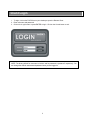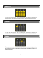
1
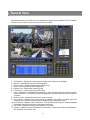
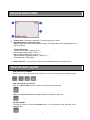
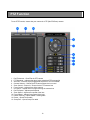
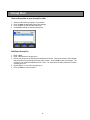
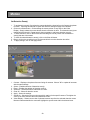
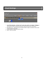
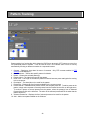
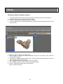
1
REMOTE VIEW ………………………………………
Client Login ………………………………………………………………………………………….
DVR Connection …………………………………………………………………………………….
Remote Client OSD …………………………………………………………………………………
View Screen …………………………………………………………………………………………
Digital Zoom …………………………………………………………………………………………
Video Event Log …………………………………………………………………………………….
Image Control ……………………………………………………………………………………….
Date & Time …………………………………………………………………………………………
Screen Capture ……………………………………………………………………………………..
Forced Recording ……………………………………………………………………….................
Sensors ………………………………………………………………………………………………
Relays ………………………………………………………………………………………………..
Audio …………………………………………………………………………………………………
PTZ FUNCTION ……………………………………...
3
5
6
7
7
8
8
9
9
10
10
11
11
11
Presets ……………………………………………………………………………………………….
Pattern Tracking …………………………………………………………………………………….
Group Run ……………………………………………………………………………….................
12
13
14
15
SEARCH & PLAYBACK ……………………………
17
EMAP ………………………………………………….
18
CLIENT SETUP ………………………………………
DVR(s) ……………………………………………………………………………………………….
Groups ……………………………………………………………………………………………….
Users …………………………………………………………………………………………………
System ……………………………………………………………………………………………….
Display ……………………………………………………………………………………………….
SERVER SETUP …………………………………….
Setup Menu Options ……………………………………………………………………................
Camera Settings …………………………………………………………………………………….
Motion ………………………………………………………………………………………………..
Audio …………………………………………………………………………………………………
Object Detection – Basic ……………………………………………………………….................
Object Detection – Advanced ………………………………………………………….................
Event Settings ……………………………………………………………………………………….
Sensor Mapping …………………………………………………………………………………….
Motion Mapping ……………………………………………………………………………………..
Alarm Notification ……………………………………………………………………….................
PTZ Settings …………………………………………………………………………….................
Presets ……………………………………………………………………………………………….
Pattern Tracking …………………………………………………………………………………….
Group Run ……………………………………………………………………………….................
Recording Schedule …………………………………………………………………….................
PTZ Schedule ……………………………………………………………………………………….
System Settings.....................................................................................................................
Network …………………………………………………………………………………..................
Emap …………………………………………………………………………………………………
Users …………………………………………………………………………………………………
Storage ………………………………………………………………………………………………
Logs ………………………………………………………………………………………………….
Import / Export Settings …………………………………………………………………………….
2
19
20
21
22
23
24
25
26
27
29
30
31
32
34
35
37
38
40
41
42
43
44
45
47
48
50
52
54
55
56
Remote View
Gain remote access to the DVR Server by installing the Remote Client (available in the CD Installer)
on the PC that you wish to have remote connection to the DVR.
1.
2.
3.
4.
5.
6.
7.
8.
9.
10.
11.
12.
PTZ Options – Displays the various presets, pattern track and group run available.
Minimize – Minimizes the Remote Client application.
Date and Time – Displays date and time of DVR Server
Close – Closes the Remote Client application.
Remote View – Displays the remote live view.
PTZ Function – Shows functions for PTZ control
DVRs – Displays list of available DVR connections. Once connected it shows the list of cameras
for the DVR server. Left-clicking on a camera displays the selected camera and sets the layout to
1-camera.
Screen Layout – Changes the screen layout of the live view.
Next Camera – Displays video of next camera or cameras. (For instance, if screen layout is at
4-camera layout, the next 4 cameras will be displayed upon pressing this button.)
Cyclic Screen – Displays videos in sequence. The cycle will follow the layout currently displayed
and will skip those layouts that only show disabled cameras.
Full screen – Displays current layout of cameras in full screen.
Frames – Limits the number of frames sent from the server. This is useful if there is a bandwidth or
CPU limitation for the remote user.
3
13. Talk – Click and hold to enable 2-way communication with server. A microphone must be
attached and the MIC boost option turned off. To talk, click and hold the button. Audio playback
will be paused during this period. Once released, audio playback will be continued. To hear the
audio from the server, the appropriate audio channel must be selected.
14. Search and Playback– Opens the Search and Playback window.
15. Emap – Opens the Emap window.
16. Mute – Mutes/Unmutes the alarm sound.
17. Help – Opens the Help window.
18. FPS and KBps – When connected, the number bytes received as well as the FPS received and
displayed are shown.
19. Connect/Disconnect button – Connect or disconnects to the selected DVR Server
20. DVR Selection – Selects the active DVR when in group mode. The relay and sensor display will
depend on the active server selected in this dropdown.
21. Image Control – Controls to adjust Brightness, Contrast, Hue and Saturation.
22. Force Record – Starts forced or manual recording.
23. Snapshot Picture – Takes a snapshot of the image displayed on-screen.
24. Video Event Log – Displays recent event logs.
25. Client Setup – Opens the Client Setup window.
26. DVR Setup – Opens the DVR Server Setup window.
27. Sensor/Relay/Audio – Selects Sensor/Relay/Audio device.
4
Client Login
1. To login, click on the DVR Client on your desktop to open the Remote Client.
2. Enter username and password.
3. Click on the Login button or press ENTER to login. Click on the Cancel button to exit.
NOTE: The factory default for username is “Admin” and for password is “password” respectively. You
can change the default username and password once you are logged in.
5
DVR Connection
To connect to a DVR
1. Select a DVR from the list.
2. Click the Connect button or double-click on the DVR Name to connect to the selected DVR.
3. A menu will appear with the option for JPEG Stream connection or MPEG Stream connection.
Select the desired connection and the application will then connect to the DVR Server.
JPEG Stream Connection
This type of connection displays the video as motion-JPEG images. The bandwidth it uses to display
one camera or 16 cameras is the same but it comes with certain limitations. The limitations to this type
of connection are:
•
•
•
•
•
•
•
Display is at most 5 frames per second
Live streaming audio is not available
Remote recording is not available
Zoom while in full screen mode is not available
Image enhancements functionality is not available
Video display will pause when someone is performing Search and Playback or Setup on the
server
The layout of the display is dependent on what is currently set on the server; changing the
layout on the server will also change the displayed layout on the remote client
MPEG Stream Connection
This type of connection streams MPEG4 video to the Remote Client. The frames per second display
follows what is set on the server just as long as the bandwidth can accommodate it. Once connected,
the number of frames received, frames displayed and the size of data received per second are
displayed for the user.
6
Remote Client OSD
1. Camera label – Indicates camera label. To modify, please go to Setup.
2. Recording Status and Recording Type
[REC] appears when there is an ongoing recording. The [REC] label is color-coded based on the
type of recording.
Types of Recording:
Continuous Recording – Magenta [REC]
Sensor-triggered Recording – Yellow [REC]
Motion-triggered Recording – Cyan [REC]
Object Detection-triggered Recording – Orange [REC]
Forced Recording – Red [REC]
3. Motion Indicator – A red border around the camera display indicates a detected motion.
View Screen Layout
View Screens in Split Mode
Switch from 1, 4, 9, or 16 channel views. Simply click on your selected layout to change the layout.
Next Camera and Cyclic Screen
Click on the Next Camera button to switch to the next camera or cameras.
Click on the Cyclic Screen button to display camera or cameras in sequence.
Full Screen Mode
To display in full screen, click the Full Screen button. To exit full screen mode, right-click on the
display screen.
7
Digital Zoom
Digital zoom allows you to zoom up to 2x.
Zoom In
On one screen layout or full screen mode, left-click to zoom in.
Zoom Out
While zoomed-in, left-click again to zoom out.
Video Event Log
The Video Event Log displays all events that the DVR system has logged. It displays the DVR Name,
DVR’s IP address, date and time, and the event that occurred.
To instantly play back the video, simply choose from the log and double-click on your selection. A
smaller playback window will appear on your screen. This functionality is only available for PC-based
DVRs.
1.
2.
3.
4.
5.
6.
7.
8.
Play – Plays playback of the video
Pause – Pauses playback of the video
Previous Frame – Moves playback to the previous frame and then pauses the playback
Next Frame – Moves playback to the next frame and then pauses the playback
Skip Back – Moves playback of the selected video 10 seconds back
Skip Forward – Moves playback of the selected video 10 seconds forward
Playback Speed indicator – Indicates playback speed
Playback Speed controls – Increases/Decreases playback speed
8
Image Control
Via Image Control, you can change brightness, contrast, hue, and saturation settings of the cameras
currently displayed.
1. Simply click on + or – to increase or decrease the selected image control option on the cameras
currently displayed.
2. To apply the changes to all cameras, click on the Apply All button.
3. Click the Reset All button to return settings to the factory default settings for all cameras.
Date and Time
Date and Time displays the current date and time of the DVR Server the Remote Client is connected
to.
9
Screen Capture
1. To capture an image of the display screen, click on the Screen Capture button.
2. A separate window will open with a printable form containing the captured image, time stamp and
camera information.
3. To print the captured image, click on Print.
4. To save the captured image, click on Save and then select the folder to save to.
5. Click on the Close button to exit the Screen Capture window.
Forced Recording
To manually start recording, click on the Record button. Click on Record button again to stop
recording.
10
Sensors
To know which sensors are active, click on the Sensor button. Active sensors are represented as
highlighted buttons. If the beep alarm notification is turned on, the system beep will also be heard.
Relays
To know which relays are active, click on the Relay button. Active relays are represented as
highlighted buttons. Relays can be activated/deactivated by clicking on the respective relay button.
Audio
To know which audio is active, click on the Audio button. The active audio channel is highlighted. Only
one audio channel can be on at any particular time. Speakers must be attached to the PC audio out to
be able to hear live audio. The audio channel can be activated / deactivated by clicking on the
respective audio button.
11
PTZ Function
To use PTZ Function, ensure that your camera is a PTZ (Pan/Tilt/Zoom) camera.
1.
2.
3.
4.
5.
6.
7.
8.
9.
10.
11.
12.
13.
Pan/Tilt buttons – Pans/Tilts the PTZ camera
PTZ Schedule – Indicates that there is/are scheduled PTZ command(s)
Auto Pan – Executes a pre-programmed sequence of PTZ commands
Camera Selector – Selects the PTZ camera channel to be control
Zoom Control – Zooms In / Zooms Out the PTZ camera lens
Focus Control – Adjusts focus of the camera
Iris Control – Adjusts amount of light entering the camera lens
Pan/Tilt Speed – Adjusts pan/tilt speed
Zoom Speed – Adjusts zoom speed of the lens
Focus Speed – Adjusts focus speed of the lens
Pattern Tracking – Opens Pattern Tracking table
Preset – Opens Preset table
Group Run – Opens Group Run table
12
Presets
To display the list of presets available, simply click on the Preset button. Presets are predefined
locations where a PTZ camera has been focused.
To set up a preset, refer to the Server Setup > Presets section.
1. Select a preset from the list.
2. Click on the Go button to run the selected preset.
13
Pattern Tracking
To display the list of pattern tracking available, simply click on the Pattern Tracking button. Pattern
tracking is a functionality which allows the DVR Server to control a PTZ camera to move from one
predefined preset to another. It can be used to have a PTZ camera scan a room or area by
automatically focusing on different locations in a sequential manner.
For details on setting up a pattern tracking sequence, refer to the Server Setup > Pattern Tracking
section.
1. Select a pattern from the list.
2. Click on the Go button to run the selected pattern.
14
Group Run
Click on Group Run to open Group Run table
1.
2.
3.
4.
Select the Group Run you wish to run or delete.
Click on Setup to add/modify Group Run settings.
Click on Go to run the selected Group Run.
Click Clear to delete the selected Group Run.
Add/Delete Group Run
1. Enter a label.
2. Enter a description for the group run.
3. Define your group run by selecting the cameras from the list. Choose the preset (of the camera)
that you wish to run by selecting from the drop list menu. Click on Add to save your settings. The
new group run will then be added to the list. Note: You must select at least 2 cameras in order to
create a group run.
4. Repeat Steps 1 to 4 to add a new group run.
5. Click on Close to exit the window.
15
Search and Playback
Remote Search and Playback can be used for thorough look-up and playback of any recorded video.
1.
2.
3.
4.
5.
6.
7.
8.
9.
10.
11.
Video Playback – Displays recorded video.
Channel Select – Selects camera(s) for playback.
DVR Selection – Selects the active DVR when in group mode.
Event Filter – Displays drop list menu for type of event
Calendar – Displays calendar.
Playback Speed – Speeds up or slows down the playback.
Full Screen – Displays video in full screen
Close – Closes Search and Playback window.
Playback Controls – Controls video playback.
Timeline – Indicates occurrence of recorded video for selected camera based on selected filters.
Record button – Starts forced or manual recording (Video quality and resolution will be based on
existing recording settings; frame rate is based on settings for Event-FPS.)
12. Snapshot Picture – Takes a snapshot of the image displayed on-screen
16
Playback Recordings
1. To search and playback recorded video, choose the type of event from the Event Filter drop list
menu. You may choose from ALL, CONTINUOUS, SENSOR, MOTION, EVENT, or FORCED
RECORDING.
2. Select the date from the Calendar. You may specify the month, year and date.
3. Select the camera by clicking on the camera number. (Simply click on the camera number again
to unselect camera.) If you see colored bars on the Timeline, that means there are recordings for
that particular period.
4. On the Timeline for Hours, double click on the colored bars to view recorded videos for that
particular hour. If there are any, recorded videos will appear as colored bars in the Timeline for
Minutes.
5. Click on the colored bars in the Minutes section to play back the recordings starting from the
minute selected. Playback will continue to other recordings until the end of the selected hour.
6. Initially, the recorded video is displayed in its original size (CIF, 1/2 D1 or D1). Left-clicking once
will maximize the display on the playback area. The second left-click will zoom in to the selected
area. Another left-click will then bring the display back to its original size.
NOTE: Sensor-triggered recordings appear as yellow bars, motion-triggered recordings appear as
blue bars, continuous recordings appear as purple bars and forced recordings appear as red bars.
Playback Controls
1.
2.
3.
4.
5.
6.
7.
Play/Pause – Plays / Pauses playback of the video
Top – Moves playback of the selected video to the first frame
Skip Back – Moves playback of the selected video 10 seconds back
Next Frame – Moves playback to the next frame and then pauses the playback
Skip Forward – Moves playback of the selected video 10 seconds forward
Playback Speed indicator – Indicates playback speed
Playback Speed controls – Increases/Decreases playback speed
17
E-map
The E-map shows a geographical representation of where the cameras, sensors and relays are
located. This functionality is only available for PC-based DVRs.
1. Under the Remote View Screen, click on the E-map button to go to E-map.
2. To view the current video for a particular camera, simply double click on the camera on the
map. A pop-up screen showing the video for that particular camera will appear.
3. To search for a particular camera, sensor or relay, simply double-click on the device under the
devices section and the map containing the device will automatically be displayed.
NOTE: Please refer to Setup for more information on how to configure the E-map function.
1.
2.
3.
4.
5.
6.
Emap Display – Displays the current selected E-map
DVR Selection – Selects the active DVR when in group mode
Maps – Displays the list of available maps
Cycle Maps – Displays maps in sequence, with a delay of 5 seconds in between each map
Devices – Displays list of cameras, sensors and relays
Emap Setup – Opens Emap Setup. Refer to DVR Setup>System>Emap for more information on
setting up your E-map settings.
7. Close – Closes E-map window.
18
Client Setup
In order to use the Remote Client to access DVR servers, you will first have to setup the connection
settings of the DVR servers that you want to connect to. This can be done by clicking on the Client
Setup button once logged in to the Remote Client application.
From the Client Setup, you can manage the DVR servers that are available to connect to, the users
who can log in to the application and other settings modifiable by the user.
19
DVR (s)
Add a DVR
1.
2.
3.
4.
Click on the DVR tab.
Click on Add button.
Enter the DVR Name.
For the connection type, pick from static IP, hostname or DDNS. Using the DDNS option requires
registration to the DDNS server. Place the DDNS server followed by a slash and the client account
name provided (i.e. www.dvr-ddns.net/client1). The DVR Name should also be set to the DVR
Name set in the DVR server.
5. Place the username and password for the server and then click on the OK button.
20
Group
Add a Group
1.
2.
3.
4.
5.
6.
Click on the Group tab.
Click on Add button.
Enter the Group Name.
Select from the dropdown the DVR you want to add to the group.
Select from camera list the camera you wish to add to the group and click on the Add button.
To remove a camera from the group listing, select the camera from the group listing and click on
the Delete button.
7. Click on the OK button to save the group settings.
21
Users
Add a User
1.
2.
3.
4.
Under Client Setup, click on the User tab.
Click on Add button.
Enter User (User ID or username), Full Name and Password. Confirm your password.
Click on OK button.
22
System
Set Alarm Sound
1. To enable Alarm Sound, select “System”. This will enable the system beep.
2. Or select “None” if otherwise.
3. Click the OK button to save your settings.
Set Recording Path
1.
2.
3.
4.
Under the File System box, click on Browse to open the search dialog box.
Search for the folder where you want your video recordings to be stored/saved.
Once you are done, click on OK to set the path.
Click the OK button to save your settings.
Set Cycle Dwell Time
1. To set how long the camera waits before moving on to the next camera in cycle mode, place the
desired number in seconds in the text box under the label Cycle Dwell Time.
2. Click the OK button to save your settings.
23
On Screen Display (OSD)
On Screen Display Options
The user has the option to display various OSD labels on the video whether in Live View or in Search
and Playback. OSD modifications will take effect even while connected to a DVR.
24
Server Setup
The DVR Server Setup can be accessed either through the DVR Server itself or through the Remote
Client application.
NOTE: Use of the DVR Setup function is only allowed if current user’s Login ID is authorized for this
function.
User Login
1. Enter the username and password.
2. Click on the Login button or press ENTER to login. Click on the Cancel button to exit.
NOTE: The factory default for username is “Admin” and for password is “password” respectively. You
can change the default username and password once you are logged in.
25
Setup Menu options
The server setup is divided into several sections each with it's own sub-menu.
Camera
This section contains the setup for the camera settings - labels, Frames Per Second (FPS), video size,
video quality, buffers, motion zones, audio quality and object detection settings.
Event
This section contains the setup for sensor and relay related settings - sensor-relay mappings,
sensor-camera mappings, sensor-ptz mappings, motion-relay mappings and alarm notification details
on these events.
PTZ
This section contains setup information on PTZ cameras - protocols, general communication settings,
presets, pattern tracking and group run.
Schedules
This section contains the setup for scheduled tasks - video recording and PTZ schedules.
System
This section contains a variety of settings - Initial overlay screen, video signal, email server settings,
DDNS settings, network configuration, Emap, user setup, storage setup and the server logs.
Import / Export
This section only contains the function for importing a previous DVR settings or exporting the current
setting for backup.
Close
The (X) on the upper right-hand area of the menu is the close button for the DVR server setup. Only
upon clicking this button will the DVR server reload the changes in the settings that have been applied
in the setup.
26
Camera Settings
1. Unique settings checkbox – Indicates whether unique settings are used per camera or
otherwise. If checked, unique settings are used per camera. To have all cameras use the same
settings, keep this option unchecked and modify the settings in Camera All.
2. Secret Status – Indicates whether the secret option is on or off for the camera. If checked, it
means that the video for that camera will not be displayed in live view. Any recording, however,
will still take place and the recording status will still appear as an On-Screen Display (OSD).
3. Enabled Status – Indicates whether the camera is enabled or otherwise. If checked, it means that
the camera is enabled.
4. MPEG4 Date/Time OSD – Indicates whether the date and time will be embedded on the MPEG4
recording as an OSD. The date/time OSD will be visible only on the modules that use the MPEG4
data (playback, remote client and setup).
5. Label – Indicates the camera label that will be displayed as an OSD in live view.
6. Sequence – Determines the display location of the specific camera in live view.
7. Normal FPS – Indicates the frames per second the video will be recorded/streamed at during
normal circumstances when continuous recording is set.
8. With Event FPS – Indicates the frames per second the video will be recorded/streamed at when an
event occurs. Events comprise of a sensor being triggered, motion being detected or when forced
recording is turned on.
27
9. Video Quality – Indicates the quality the video will be recorded/streamed at. Five settings are
available from Very High, High, Medium, Low, Very Low. With higher video quality, though, the file
size of the recording will also increase.
10. Video Size – Indicates the resolution size the video will be recorded/streamed at. For NTSC the
settings are 720x480 (D1), 720x240 (1/2 D1) and 360x240 (CIF). For PAL the settings are
720x576 (D1), 720x288 (1/2 D1) and 360x288 (CIF). The higher the resolution, the bigger the size
in the recording file size. There is a limitation on the combination of settings for the Video Size in
conjunction with the With Event FPS. Please see the note below for more details on this.
11. Pre-Record Buffer – Indicates how long in seconds the recording will be buffered at the start of an
event recording.
12. Post-Record Buffer – Indicates how long in seconds the recording will be buffered at the end of an
event recording.
13. Restore Defaults – Restores the default settings.
14. Apply – Saves the settings.
Important Note:
Example model IVS-16B, IVS-6R
Camera 1 to 16 has a maximum total capture speed of 480/400 fps for NTSC/PAL. This allows 30/25
fps per camera at CIF resolution. With larger video sizes, the set fps becomes equivalent to double,
for 1/2 D1 resolution, and quadruple, for D1 resolution, when calculating the total capture speed for 16
cameras. Because of this, the maximum fps that can be set when cameras 1 to 16 are all set to D1 is
7.5 fps for NTSC.
28
Motion
Set Detection Zone(s)
1. To set detection zone(s), first select the camera desired by choosing from the Camera drop down
list menu. Choosing the Camera All option will allow the settings to apply to all cameras.
2. Click on the Select button. Click and drag the mouse pointer on any area on the Video
Display. Simply release the mouse button when the selection is done. The detection zone(s) are
marked with a white grid. Repeat step 2 when necessary to add more detection zone(s).
3. To erase selection, click on the Erase button and drag the mouse pointer over the detection
zone(s) that are to be erased.
4. To clear all selected detection zone(s), click on the Clear All button.
5. Drag or click on the sensitivity bar to set how sensitive the motion detection should be.
6. To apply settings, click on the Apply button.
1. Camera – Displays a drop down list menu listing all cameras. Choose "All" to update all cameras
with the same settings.
2. Select – Enables selection of detection zone(s).
3. Erase – Enables the deletion of detection zone(s).
4. Select All – Selects the entire video area as a zone.
5. Clear All – Clears all detection zones.
6. Apply – Saves the settings.
7. Sensitivity – Shows the current motion sensitivity setting for the specific camera. The higher the
value is, the more sensitive the motion detection will be.
8. Video Display – Shows current view of selected camera as well as the selected detection zones.
Movement detected within the zones will highlight the specific area within the selected zone.
29
Audio
1. Audio Output volume control – Shows current output volume. Click on the + or - to increase or
decrease the output volume respectively. This setting does not affect the audio volume set in the
live view and is used only when testing the audio during setup.
2. Unique settings checkbox – Indicates whether unique settings are used per audio or otherwise. If
checked, unique settings are used per audio. To have all audio use the same settings, keep this
option unchecked and modify the settings in Audio All.
3. Enabled status – Indicates whether the audio is enabled or otherwise. If checked, it means that
the audio is enabled. If the audio is disabled, the input gain controls will not be displayed. If there
are no audio inputs, disable the audio to save on storage space.
4. Input Gain volume control – Shows current input gain volume. Click on the + or - to increase or
decrease the input gain of the specific audio.
5. Test Audio – Tests current input gain settings. NOTE: Test button will only appear if setup is done
on the server. You will need speakers attached to the audio out of the PC to be able to hear the
live audio.
6. Restore Defaults – Restores the default settings.
7. Apply – Saves the settings.
30
Object Detection - Basic
Set Object Detection Zone(s)
1. To set object detection zone(s), first select the camera desired by choosing from the Camera drop
down list menu. Choosing the Camera All option will allow the settings to apply to all cameras.
2. Click and drag the mouse pointer on any area on the Video Display. Simply release the mouse
button when the selection is done. The object detection zone(s) are marked with a white
grid. Repeat step 2 when necessary to add more detection zone(s). Zones should not overlap
one another and there is a maximum of eight (8) zones per camera.
3. To clear all selected detection zone(s), click on the Clear All button.
4. To apply settings, click on the Apply button.
1. Camera – Displays a drop down list menu listing all cameras. Choose "All" to update all cameras
with the same settings.
2. Select All – Selects the entire video area as one zone.
3. Clear All – Clears all object detection zones.
4. Apply – Saves the settings.
5. Video Display – Shows current view of selected camera as well as the selected detection zones.
6. Minimum Object Size – Displays the minimum object size to be detected within the selected
zone(s). The size detected follows the area size indicated and not the shape displayed. For
customized object size, select Other and place the desired block size.
NOTE: This setup page will only appear if the server specifications meet the minimum hardware
requirements of at least a Core 2 Duo processor and 2GB memory.
31
Object Detection - Advanced
Objection detection depends on two pictures - the background picture and the foreground picture. The
differences between the two pictures are the missing objects, new objects or displaced objects.
The advanced settings allow users to adjust the performance of the feature to adapt to the installation
camera environment
1. Unique settings checkbox – Indicates whether unique settings are used per camera or
otherwise. If checked, unique settings are used per camera. To have all cameras use the same
settings, keep this option unchecked and modify the settings in Camera All.
2. Activity Level – This parameter describes the general activity of the scenario. The options are
High, Medium and Low. Examples of scenes with high activity are mall entrances, train stations
and airport lobbies. High activity scenes can be described as scenes that are always or almost
always in a state of flux - people come and go fairly quickly. Examples of scenes with low activity
are jewelry stores, secluded areas and stock rooms. Low activity scenes can be described as
scenes that people don't visit often.
Continue next page …
32
3. Movement – Movement is a parameter that describes how people in a scene moves. The options
are Very Fast, Fast, Medium, Slow and Very Slow. Examples of scenes where people move
quickly are corridors, mall entrances and fire exits. In these scenarios, people don't stay at one
place for even a small amount of time - they move continuously.
On the other end, scenes where people don't move too much are conference rooms, restaurants
and private offices. In these places, people tend to stay where they are for some time. Note,
however, that it is possible for people to keep still for a long time that the computer may consider
them an inanimate object.
Anywhere in between are scenes like people waiting for an elevator, people lining up to buy tickets
and people waiting for a green line so they can cross the street. The important consideration here
is how long people tend to stay where they are. Below is a rough equivalence:
a) Very fast would be constantly moving.
b) Fast would be "pausing for a moment".
c) Medium would be "staying in place for a few seconds".
d) Slow would be "staying in place for a couple of seconds".
e) Very slow would be "keeping still for about half a minute".
4. Sensitivity – This parameter controls how the computer responds to changes in scenes. The
options are High, Medium and Low.
5. Video Clarity – This parameter controls how the computer handles video noise. Select what most
closely describes the video clarity. The options are Excellent, Good, Fair, Poor and Noisy.
6. Restore Defaults – Restores the default settings.
7. Apply – Saves the settings.
NOTE: This setup page will only appear if the server specifications meet the minimum hardware
requirements of at least a Core 2 Duo processor and 2GB memory.
33
Event Settings
1. Sensor/Relay Operation – Indicates if sensors and relays operation are enabled or disabled. If
there are none attached to the DVR Server, make sure that this is set to disabled. To be able to
map sensors to relays or cameras and cameras to relays, this option has to be enabled.
2. Relay Reset Time – Indicates the time in seconds it takes for relays to reset back to normal mode
if the reset mode is time-based.
3. Restore Defaults – Restores the default settings.
4. Apply – Saves the settings.
34
Sensor Mapping
Map Sensors
1. To map the sensors to cameras, simply select Cameras in the Sensor Mapping option. Click on
the grid to place an "O" to mark the sensor-camera mapping. Once a sensor has been mapped to
a camera, this means that when that particular sensor is triggered, such as when a smoke detector
detects smoke, the camera which is mapped to that sensor will start to record. NOTE: You can
map one sensor to more than one camera and vice versa. When applied, this means that when a
smoke detector or infrared motion sensor are triggered, the camera that is mapped to these
sensors will start to record.
2. To map the sensors to relays, simply select Relays in the Sensor Mapping option. Click on the
grid to place a mapping. Depending on what reset mode is selected in the drop down list menu,
the appropriate mark will appear on the grid. A "T" for time-based reset mode, an "S" for sensor
synchronized reset mode or an "X" for manual reset mode. Once a sensor has been mapped to a
relay, this means that when that particular sensor is triggered, such as when a smoke sensor
detects smoke, the relay which is mapped to that sensor will either open or close. NOTE: You can
map one sensor to more than one relay and vice versa. When applied, this means that when a
smoke detector or an infrared proximity sensor are triggered, the relay that is mapped to these
sensors will open or close, i.e. light will turn on.
3. To apply settings, click on the Apply button.
1. Sensor Mapping – Indicates what sensor mapping is currently displayed; mapping to cameras or
relays. The active mapping is also indicated above the mapping area.
Continue next page …
35
2. Reset Mode – Indicates the reset mode for sensor-relay mappings. This is disabled when the
sensor mapping is set to cameras. The reset mode options are Time, Sensor Synchronized and
Manual.
Time-based reset mode follows the relay reset time set in the General Event Settings.
Sensor synchronized reset mode follows the status of the sensor. If the sensor is turns off, then
so does the relay. Manual reset mode means the relay will not reset back to normal unless
manually reset.
3. Normal State – Indicates what the normal state of the sensor is set to. If the sensor is normally set
to “OFF”, then click on the normal state to set it on.
4. Map PTZ – Indicates if the sensor will be mapped to a PTZ action when it is triggered. If this is
unchecked, then the PTZ On, PTZ Off and Dwell Time options are also disabled.
5. PTZ On – Displays a drop down list menu of available PTZ presets and group runs that can be
called when the sensor is triggered.
6. PTZ Off – Displays a drop down list menu of available PTZ presets and group runs that can be
called when the Dwell Time length has been reached.
7. Dwell Time – Indicates the length in seconds on how long the PTZ will remain in the PTZ On
position before going to the PTZ Off position.
8. Mapping – Indicates the mapping that have been set. For sensor-camera mappings, an "O"
signifies that there is a mapping there. For sensor-relay mappings, a "T" signifies a mapping that
has a time-based relay reset mode. An "S" signifies a mapping that has a sensor-synchronized
relay reset mode. An "X" signifies a mapping that has a manual relay reset mode.
9. Restore Defaults – Restores the default settings.
10. Apply – Saves the settings.
36
Motion Mapping
Map Camera Motion
1. To map the cameras to relays, click on the grid to place a mapping. Depending on what reset
mode is selected in the drop down list menu, the appropriate mark will appear on the grid. A "T" for
time-based reset mode, an "M" for motion synchronized reset mode or an "X" for manual reset
mode. Once a camera has been mapped to a relay, this means that when that particular camera
detects motion, the relay which is mapped to that camera will either open or close. NOTE: You
can map one camera to more than one relay and vice versa. When applied, this means that when
motion is detected in any of the cameras, the relay that is mapped to these cameras will open or
close, i.e. light will turn on.
2. To apply settings, click on the Apply button.
1. Reset Mode – Indicates the reset mode for camera-relay mappings. The reset mode options are
Time, Motion Synchronized and Manual. Time-based reset mode follows the relay reset time set
in the General Event Settings. Motion synchronized reset mode follows the status of the camera.
If the camera no longer detects motion, then the relay turns off. Manual reset mode means the
relay will not reset back to normal unless manually reset.
2. Mapping – Indicates the mapping that have been set. For camera-relay mappings, a "T" signifies
a mapping that has a time-based relay reset mode. An "M" signifies a mapping that has a
motion-synchronized relay reset mode. An "X" signifies a mapping that has a manual relay reset
mode.
3. Restore Defaults – Restores the default settings.
4. Apply – Saves the settings.
37
Alarm Notification
1.
2.
3.
4.
5.
6.
7.
8.
9.
10.
11.
Port – Displays a drop down list menu for port settings.
Data Bit – Displays a drop down list menu for data bit settings.
Baud Rate – Displays a drop down list menu for baud rate settings.
Parity – Displays a drop down list menu for parity settings.
Stop Bit – Displays a drop down list menu for stop bit settings.
Unique settings checkbox – Indicates whether unique settings are used per camera or
otherwise. If checked, unique settings are used per camera. To have all cameras use the same
settings, keep this option unchecked and modify the settings in Camera All.
Motion Border – Indicates whether the motion border alarm notification is enabled or not. If
checked, it means that a red border will appear around the video in live view if motion is detected.
Object Detection Mask – Indicates whether the object detection mask alarm notification is enabled
or not. If checked, it means that a transparent blue mask will appear around the area in live view
where a new object was placed or where an object was removed.
Emap – Indicates whether the e-map alarm notification is enabled or not. If checked, it means that
when motion is detected for that camera the camera icon in the Emap will then blink.
Beep – Enables/disables the system beep when an alarm is triggered.
E-mail – Indicates whether e-mail alarm notification is enabled or not. If checked, it means that an
e-mail notification will be sent to the specified e-mail along with a jpeg screenshot attached to it
when an alarm occurs for that specific camera.
Continue next page …
38
12. E-mail Address – Displays e-mail address used for the e-mail alarm notification.
13. SMS – Indicates whether SMS alarm notification is enabled or not. If checked, it means that an
SMS notification will be sent to the specified cell number when an alarm occurs for that specific
camera.
14. Cell No. – Displays cell phone number used for the SMS alarm notification. The country code
must be included in the entry.
15. Email and SMS Notification Delay – Sets the minimum delay between email and SMS
notifications. If an alarm is triggered for a specific camera and an email or an SMS notification has
already been sent, an email or SMS will not be sent again for that camera if the same type of alarm
is triggered within the delay period. This is to prevent the spamming of email and SMS
notifications.
16. Restore Defaults – Restores the default settings.
17. Apply – Saves the settings.
39
PTZ Settings
1.
2.
3.
4.
5.
6.
7.
8.
9.
10.
11.
12.
13.
14.
15.
Port – Displays a drop down list menu for port settings.
Data Bit – Displays a drop down list menu for data bit settings.
Baud Rate – Displays a drop down list menu for baud rate settings.
Parity – Displays a drop down list menu for parity settings.
Stop Bit – Displays a drop down list menu for stop bit settings.
With PTZ – Indicates the PTZ status of the camera. If checked, it means that the camera is
equipped with PTZ capabilities.
Protocol – Displays a drop down list menu for supported PTZ protocols. Currently supported PTZ
protocols include Pelco D, Pelco P, Merit Li-Lin, DynaColor (DSCP), and VISCA SNC-R225.
NOTE: VISCA SNC-R225 protocol does not have auto-pan or iris functionality. It also only
supports 6 preset positions.
Address – Indicates the address to be used for the PTZ camera. This address has to be unique
across all enabled PTZ cameras.
Motion Tracking – Indicates if motion tracking for the PTZ is enabled. If enabled, the PTZ will track
motion that is detected within it's field of vision.
Tracking Speed – Displays the tracking speed the PTZ camera uses to track detected motion.
Increasing or decreasing this value will allow the user to calibrate the PTZ to track more smoothly.
PTZ Speed – Displays the movement speed of the PTZ camera. Increasing or decreasing this
value will allow the user to calibrate the PTZ to track more smoothly.
Home Preset – Displays the preset location that the PTZ camera will move back to once a certain
length of inactivity is reached.
Inactivity Reset – Displays how long in seconds the PTZ camera will wait before going back to the
home preset location once there is no more motion activity detected.
Restore Defaults – Restores the default settings.
Apply – Saves the settings.
40
Presets
Presets are predefined locations where a PTZ camera has been focused.
1. Camera – Displays a drop down list menu of cameras. Only PTZ cameras enabled in PTZ
Settings will be displayed.
2. Preset List – Displays the list of presets that have been defined for the selected camera.
3. Delete – Deletes a selected preset(s) from the preset list.
4. PTZ Control buttons – Controls the PTZ camera.
5. Add – Adds the current PTZ position as a preset for the current camera. The name of the preset
will be based on what is placed in the text box.
6. Video Display – Displays the camera view.
41
Pattern Tracking
Pattern tracking is a functionality which allows the DVR Server to control a PTZ camera to move from
one predefined preset to another. It can be used to have a PTZ camera scan a room or area by
automatically focusing on different locations in a sequential manner.
1. Camera – Displays a drop down list menu of cameras. Only PTZ cameras enabled in PTZ
Settings will be displayed.
2. Pattern selector – Selects the specific pattern for deletion.
3. Delete – Deletes the selected pattern(s).
4. Pattern Label – The label to be used for the pattern.
5. Dwell Time – The length in seconds the pattern will wait in between preset settings before moving
to the next preset.
6. Description – The description to be used for the pattern.
7. Presets list – Displays the list of presets available for the current camera.
8. Preset selector – Adds/Removes presets to/from the selected preset list. To add a preset to the
pattern, simply select a preset or several presets from the Presets list and click on the right arrow.
To remove a preset or several presets from the pattern, select the preset(s) from th Selected
Presets list and click on the left arrow. The order of the selected presets will be the order that the
pattern will be run.
9. Selected Presets list – Displays the list of selected presets to be used for the pattern.
10. Add – Adds a new pattern based on the fields set.
42
Group Run
A group run is a functionality that allows the DVR Server to simultaneously redirect the focus of several
PTZ cameras to specific areas.
1. Group selector – Selects the specific group for edit or deletion.
2. Add – Opens the "Add Group Run Settings" setup page to allow the user to add a new group run.
3. Edit – Opens the "Edit Group Run Settings" setup page to allow the user to edit the selected
group.
4. Delete – Deletes the selected group(s).
Add/Edit Group Run
1. Group Name – The group name to be used for the group run.
2. Description – The description to be used for the group run.
3. Camera selector – Cameras that have defined presets will be enabled and can be selected to be
part of a group run. In order to create a group run, at least two cameras have to be selected.
4. Preset list – Displays a drop down list menu of presets available for the specific camera.
5. Set – Adds/Edits the group run based on the fields set.
6. Close – Closes the "Add/Edit Group Run Settings" setup page.
43
Recording Schedule
Set Recording Schedule
1. To set recording schedules, first select the camera desired by choosing from the Camera drop
down list menu. Choosing the Camera All option will allow the settings to apply to all cameras.
2. Click and drag the mouse pointer over the grid to select the area to schedule for recording. Once
you release the mouse pointer, a menu will appear, indicating the recording options: C –
Continuous, M – Motion, D – Object Detection, S – Sensor, F – Forced, E – Event = Sensor and
Motion and Object Detection, X – No Recording or Cancel to cancel the selection. When the
recording is set to sensor, then only sensor triggered events are recorded. When motion
recording is set, only motion detected events are recorded. Event recordings allow for motion,
sensor and object detection events. However, if all of these events are triggered, sensor recording
takes priority, then object detection and lastly motion. Continuous recording simply sets the
camera to record all the time but should a sensor, motion or object detection event be triggered,
the recording will be changed according to the event type triggered. The Forced recording option,
is similar to the Continuous recording option except that it will ignore all triggered events.
3. To apply settings, click on the Apply button.
1. Camera – Displays a drop down list menu listing all cameras. Choose "All" to update all cameras
with the same settings.
2. Recording Schedule grid – Displays the complete recording schedule.
3. Recording Type menu – After selecting a time period, this menu will appear where the user can
select what type of recording will be assigned to the selected time period. Possible recording
options are Continuous, Motion, Object Detection, Sensor, Forced, Event or No Recording.
4. Restore Defaults – Restores the default settings.
5. Apply – Saves the settings.
44
PTZ Schedule
Add / Delete PTZ Schedule
1. Under PTZ Schedule, select the groups, presets or patterns from the PTZ Type and List menus.
2. Select your Start day and time.
3. Select your End day and time. To select until the end of a particular day, set the day to the
succeeding day and set the time to 00:00. For example, to set the entire day for Monday, set the
Start to Monday 00:00 and then set the End to Tuesday 00:00. If the Start day and time is less
than the End day and time, then the schedule will wrap around the week. For example, if the Start
is set to Wednesday 00:00 and the End is set to Monday 00:00, then the schedule will take effect
on all days except Monday and Tuesday.
4. Then, click on Add. The new schedule will then be added to the list. Pink bars indicate group
runs, blue bars indicate presets, and red bars indicate patterns.
5. To delete a schedule, make a selection on the timeline in order to display the schedule(s) in the
bottom left area for that particular day and hour. Select the schedules to delete by checking the
checkbox next to the desired schedules and then click on Delete. A dialog box will pop up,
confirming if you wish to delete the schedule. Click on OK to delete the schedule or click on
Cancel if you choose otherwise.
1. PTZ Schedule status – Indicates if PTZ schedule is enabled or otherwise. If checked, it means
that the PTZ schedule function is enabled.
2. Schedule selector – Displays the list of scheduled PTZ functions in a given period. To select a PTZ
schedule for deletion, simply check the checkbox next to the desired schedule. To select all listed
schedules, check the topmost checkbox.
3. Delete – Deletes the selected PTZ schedule(s).
4. PTZ Type – Displays a drop down list menu for the types of PTZ functions to be scheduled:
presets, pattern tracking and group.
Continue next page …
45
5. List – Displays a drop down list menu of the selected PTZ Type. If in the PTZ type, preset was
selected, then this list will display a complete list of all the presets available.
6. Start/End – Displays a drop down list menu for the start / end day and time of the PTZ schedule.
7. Add – Adds a new PTZ schedule based on the fields set. Should there be any conflicts in the PTZ
schedules, the system will not insert the schedule and inform the user of the conflict.
8. PTZ Schedule Display – Displays all scheduled PTZ functions
9. Apply – Saves the settings.
46
System Settings
1.
2.
3.
4.
5.
6.
7.
8.
9.
10.
11.
12.
13.
DVR Name – This is the name to be used by the DVR server.
Location – The location of where the DVR server is.
Description – The description of the specific DVR server.
Initial Overlay Screen – Displays the default screen layout when the DVR server starts.
Cycle Dwell Time – The time the system waits before moving to the next camera(s) when in cyclic
screen mode.
Auto-lock Duration – The time the system waits before locking the application due to user
inactivity.
Enable Watermark – Enables / Disables incorporation of a watermark into the video recording.
The user can verify in Search and Playback the video recordings that could have been modified or
altered. When the application determines that a video has been modified, a window will pop-up
indicating that the specific image has been altered.
Video Signal – Displays the current video signal.
SMTP Server – Displays the SMTP server address.
Username – Displays the username to be used when validating for the SMTP server.
Password – Displays the password to be used when validating for the SMTP server.
Restore Defaults – Restores the default settings.
Apply – Saves the settings.
47
Network
1. DVR Name – This is the name to be used by the DVR server. If the DVR server will be registered
to the DDNS server, then the DVR Name must be unique per client account.
DDNS Server Settings
The DDNS server setup allows the DVR server to be globally accessible by the Remote Client even if
the DVR Server has a dynamic IP address. The DDNS server is a separate application which should
be installed on a different machine.
2.
3.
4.
5.
6.
7.
DDNS Server – The IP Address or domain name of the DDNS server.
Port – The port to be used for the DDNS server.
Username – The username to be used to validate the account in the DDNS server.
Password – The password to be used to validate the account in the DDNS server.
Client Account – The client account name given by the administrator of the DDNS server.
Auto Connect to DDNS – To set the server to automatically update the DDNS server of any
changes in the IP address of the DVR server, check this option.
Network Configuration
8. Use DHCP – To use Dynamic Host Configuration Protocol (DHCP) check this option. By default
the DVR server uses DHCP. When unchecked a static IP for the server can be set and the options
for IP Address, Subnet Mask and Gateway Address are enabled.
Continue next page …
48
9. IP Address – If DHCP is enabled, then this displays the IP currently set for the DVR server. If
DHCP is disabled, use this field to enter the static IP address.
10. Subnet Mask – The subnet mask to be used for the static IP.
11. Gateway Address – The gateway address to be used for the static IP.
12. Primary DNS – The primary DNS to be used for the static IP.
13. Secondary DNS – The primary DNS to be used for the static IP.
14. Ports – Displays the various ports used by the DVR and related applications.
15. Restore Defaults – Restores the default settings.
16. Apply – Saves the settings.
49
Emap
Set Camera, Sensor and Relay Locations
1.
2.
3.
4.
To set the locations for cameras, sensors and relays, select the map first from the Map List.
Drag the device icons onto the map to set the location.
Click on the Apply button to apply and save your settings.
To remove the device icons, simply drag the device icons out of the map and they will return to the
device icon list.
1. Map List – Displays the list of available maps.
2. Emap Display – Displays the current selected E-map with the device icons placed in
user-specified locations.
3. Device Icons – Displays the list of device icons. Yellow icons are for cameras, blue icons are for
sensors and green icons are for relays.
4. Add – Displays a section to allow the user to add more maps.
5. Edit – Displays a section to edit the map’s name and description.
6. Delete – Deletes the selected map from the map list.
7. Apply – Saves the settings.
50
Add Emap
When the Add button is clicked, the lower part of the Emap displays a section to allow the user to
upload additional electronic maps. Click on Browse to select a JPEG image for upload. Enter the
name of the map and its description. To upload the map, click on the OK button. Otherwise, click
cancel to hide the Add Emap section.
Edit Emap
When the Edit button is clicked, the lower part of the Emap displays a section to allow the user to
modify the name and description of the selected Emap.
51
Users
1.
2.
3.
4.
5.
User selector – Selects the specific user either for editing or deletion.
Add – Opens a new page to add a new user.
Edit – Opens a new page to edit the selected user.
Delete – Deletes the selected user(s).
Edit Access – Opens a new page to edit the access rights of the specific user.
NOTE: The Admin e-mail address indicated on the Users Settings table is also used when sending an
alarm notification. The Admin account also cannot be deleted.
Add / Edit User
To add a user, just click on the Add button in the users setup page and a new page will open up where
the user information can be added/edited. Saving the data will then display the list of users once
again. When editing an existing user, the Login Name of the user can no longer be modified.
Continue next page …
52
Edit User Access
Clicking on the Edit User Access button will display the page where the access rights of the user can
be modified. Here, access to specific functionalities can be set per user. When the Remote View or
Web View functionality is selected then the Remote Surveillance permissions are enabled, allowing
the setup for specific cameras only.
Users can also be limited based on specific hours of a day. Simply click and drag to change the status
of access rights. Red blocks mean that remote client access for this user is restricted. Green means
there is no restriction to that hour.
NOTE: For the Admin account, the setup functionality cannot be removed.
53
Storage
1. Drive Information – Displays the name of the partition, total space, used space, available space,
used space in percentage, and mount directory of the available partitions in the DVR server.
2. Delete old files – This option allows the deletion of old files when all Video DBs are full. If this is
unchecked and all the space in Video DBs are full, then the DVR server will stop recording.
3. Path – Displays the directory where recorded videos are stored. This cannot be modified.
4. Auto-allocate – New hard disks formatted and mounted on the DVR server will not automatically
be used as storage space by the DVR server. The auto-allocate function will make use of these
hard disks by allocating a Video DB for each new device detected.
5. Apply – Saves the settings.
54
Logs
1. Log Option – Indicates what logs are currently displayed; System Events or System Logs.
2. Search category – Displays a drop down list menu of the different search categories. For System
Events the search categories are Camera No, Event Type and Event Time. For System Logs the
search categories are Audit Time, Status, Action and Remarks.
3. Search description – Keywords for searching within the Search Category. "%" can be used as a
wild card but keep in mind that the search is case-sensitive.
4. Page size limit – Indicates the limit of the page size of the search results.
5. Go – Starts the search based on the search criteria.
6. Search results – Displays the results of the executed search. Columns in the search results vary
depending on the type of log selected.
7. Search page navigation – Navigates the results pages.
55
Import / Export Settings
User's can export the setup settings of the DVR in case they want to back it up. Exported DVR
settings are saved as settings-YYYYMMDD.dvr. They can use the import facility to load previously
exported settings.
Export DVR Settings
1. Click on Browse button. A window will open showing the file directory of Server.
2. Browse for destination folder
3. Click Export button
Import DVR Settings
1. Click Browse button and locate the .DVR file you want to import
2. Click the Import button
1. Import – Imports DVR settings. Click on the Browse button to search for a DVR settings file to
upload to the server.
2. Export – Exports DVR settings. Click on the Browse button to select the location of where the
DVR settings file will be saved.
3. File Directory of Server – Displays the location of where the DVR settings file will be saved.
Note: The Import/Export menu is only available when performing setup on the DVR Server.
56