1
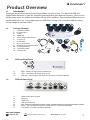
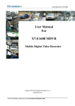
DIGITAL VIDEO SECURITY SYSTEM
WITH 500GB HARD DRIVE
Model Number: IT115008
INSTRUCTION MANUAL
After Sales Support
1300 663 907
[email protected]
Model Number IT115008
i
Digital Video Security System
Warranty Details
The product is guaranteed to be free from defects in workmanship and parts for a period
of 12 months from the date of purchase. Defects that occur within this warranty period,
under normal use and care, will be repaired, replaced or refunded at our discretion.
The benefits conferred by this warranty are in addition to all rights and remedies in respect
of the product that the consumer has under the Competition and Consumer Act 2010 and
similar state and territory laws.
Our goods come with guarantees that cannot be excluded under the Australian Consumer Law.
You are entitled to a replacement or refund for a major failure and for compensation
for any other reasonably foreseeable loss or damage. You are also entitled to have the goods
repaired or replaced if the goods fail to be of acceptable quality and the failure
does not amount to a major failure.
AFTER SALES SUPPORT
AUS
1300 663 907
[email protected]
MODEL: IT115008 PRODUCT CODE: 49140 02/2015
1
YEAR WARRANTY
Safety Instructions
1.
Read instructions
Carefully read all safety instructions and the user manual before operation.
2.
Power source
Only use the supplied power adaptors. Using other power adaptors may cause damage to the unit or potentially start a fire. For INDOOR use only.
3.
Do not expose the DVR unit to moisture
Avoid installing the DVR unit in a location with high humidity or in a location where liquid may spill onto the unit. Liquid may cause a short circuit which can result in electric
shock or fire.
4.
Do not expose to heat sources
Do not install near any heat sources such as radiators, stoves or other appliances that produce heat.
5.
Do not expose to dust
Do not use the DVR unit in dusty areas as dust can impair electronic components.
6.Cleaning
Unplug all equipment from the wall outlet before cleaning. Do not use liquid aerosol cleaners. Use a damp soft cloth for cleaning.
7.Lightning
Unplug all equipment during lightning storms to prevent damage. Unplug the DVR unit if it will not be used for long periods of time.
8.
Modifications & attachments
Never add any attachments and/or equipment without the approval of the manufacturer. Unauthorized modifications may result in fire, electric shock or other personal injury and may void your warranty.
9.Ventilation
Do not block any ventilation holes. Do not place objects on top of or cover the
ventilation holes on the sides of the DVR unit.
10.
Grounding mounted equipment
If mounting the DVR unit into a rack, ensure the rack is properly grounded before powering on and using the DVR unit to prevent electric shock and fire.
11.
Do not open DVR unit case
There are no user serviceable parts inside the DVR unit. Modifying any parts may void
your warranty.
After Sales Support
1300 663 907
[email protected]
Model Number IT115008
iii
Contents
Warranty Details
ii
Safety Instructions
iii
1
– Product Overview
1
1.1 Introduction1
1.2 Package Contents 1
1.3 DVR Unit Front Panel1
1.4 DVR Unit Rear Panel1
2
– DVR Unit Installation2
2.1 Installation Location2
2.2 DVR Unit Connections 2
3
- Using the DVR Unit for the First Time
4
3.1 Mouse 4
3.2
Powering on the DVR unit
4
3.3
Setup Wizard4
3.4
Main Screen4
3.5
Navigating the DVR Menus4
3.6 Quick Popup Menu5
3.7 Setting the Date and Time5
4
- DVR Unit Menu6
4.1 DVR Unit Menu Map6
4.2 Main Menu7
4.3
Display7
4.3.1
Live Settings7
4.3.2
Output8
4.3.2
Privacy Zone8
4.4
Record9
4.4.1
Recording Parameters9
4.4.2
Schedule Recording10
4.4.3
Main Stream10
4.5 Search11
4.5.1
Record Search11
4.5.2
Event Search12
4.5.3
Backup12
4.5.4
Log13
4.6
Networking13
4.6.1
Network14
4.6.2
Sub Stream (Network)14
4.6.3
DDNS15
4.6.4
Email15
4.7 Alarm16
4.71 Motion16
After Sales Support
1300 663 907
[email protected]
Model Number IT115008
iv
Contents
4.8 Device16
4.8.1 HDD
16-17
4.8.2 PTZ
17
4.9 System18
4.9.1
General18
4.9.2
Users19
4.9.3
Version20
4.10 Advanced20
4.10.1
Maintain20
4.10.2
Events20
5
- Viewing footage on your computer
21
5.1 Installing the Video Player Software
21
5.2 Playing Backup Footage21-22
6
- Appendix 1 - Networking23
6.1 Internet Explorer - ActiveX Settings
23-24
6.2 Additional Windows Settings25-26
6.3 Logging Into the DVR unit over Internet Explorer or Safari
27
7
- Appendix 2 - Troubleshooting & Support
28
7.1 Troubleshooting28-30
7.2 Glossary of Terms30
8
- DVR Specifications31
9
- Camera Specifications32
Repair and Refurbished Goods or Parts Notice
33
After Sales Support
1300 663 907
[email protected]
Model Number IT115008
v
Product Overview
1.1Introduction
Thank your for purchasing the Cocoon Digital Video Security System. This powerful DVR unit
(Digital Video Recorder) is ideal for monitoring and recording your home or business. We trust you
will get many years of carefree and reliable use out of this product. Please read and follow the user
manual before first use. If you experience any difficulties setting up or using this product, please
see back page for contact details:
2
1.2
1.3
Package Contents
1.
2.
3.
4.
5.
6.
7.
8.
9.
10.
11.
12.
3
1 x DVR with 500GB HDD
4 x Security Cameras
1 x Mouse
1x HDMI cable
2 x Power Adaptors (DVR & Camera)
1 x Software CD
4
4 x CCTV Stickers
1 x 4-way Power Splitter
4 x Mounting Screws & Plugs for Cameras
4 x 18m Extension Cables
1 x Audio/Video Splitter
1 x Ethernet Cable
8
1
6
5
CCTV
7
12
SURVEILLANCE
IN USE
- Instruction Manual
- Backup Software
10
9
11
DVR unit Front Panel
1
2
3
1.
2.
3.
1.4
PWR – Power LED lights when powered on
HDD – Hard Drive LED lights when in use
USB Port – Front USB port for flash drive backup / firmware updates
DVR unit Rear Panel
1
1.
2.
3. 4.
5.
6.
7.
2
3
4
5
6
7
Video/Audio Input/Output
VGA Port
HDMI Port
USB Port for mouse
LAN – Ethernet connection to modem / router (required for remote viewing over internet or mobile)
RS485 – For use with PTZ cameras (Cable and PTZ camera not included)
12V Socket – Connect 12V Power Adaptor
After Sales Support
1300 663 907
[email protected]
Model Number IT115008
1
2 – DVR unit Installation
2.1 Installation Location
Before installing the security system, it is essential to plan where to locate the DVR unit.
Below are a few points to consider
•
•
•
•
•
•
•
The DVR unit should be positioned in a central location with easy access to mains power, cameras and installed cables
If you plan to use remote viewing features, the DVR unit should be located near your modem / router or Ethernet network point
The DVR unit should be installed in a secure location to avoid tampering
Do not place heavy objects on top of the DVR unit
Do not block ventilation holes on the top and sides of the DVR unit or use in an enclosed area which may cause overheating
Plan out where you would like to place your cameras and test all connections BEFORE permanently installing cables and cameras
Cameras should be placed covertly indoors where you do not want to see them everyday. Outdoor cameras can be placed in plain sight to act as a deterrent to would-be intruders
2.2 DVR unit Connections
1. Connect each of the camera extension cables to the camera video and power connectors
2. Connect the other end of the extension cables to the video cable splitter, and then
connect the cable splitter to the port marked “Video Input 1-4”
3. Connect the 4-way power splitter to each of the extension cables (red)
After Sales Support
1300 663 907
[email protected]
Model Number IT115008
2
2 – DVR unit Installation
4. Connect the included HDMI cable to the back of the DVR unit and connect the other end of the cable to your monitor or TV. Note you must switch your TV or monitor to the correct INPUT once the DVR unit has been powered on
For example:
HDMI1
5. Connect the mouse to the USB port
(on the back of the DVR unit)
6. Connect the power adaptor to the 4 way splitter and plug into a mains outlet.
Switch the outlet on. Note either power adaptor can be used, they are identical
Note: Power adaptors for
indoor use only
7. Connect the power adaptor to the DVR unit and plug into a mains outlet.
Switch the outlet on. The DVR unit will begin the boot sequence
Note: Both the DVR unit and cameras operate “always on”. To turn the cameras or DVR unit off,
switch off the power adaptors at the power outlet
Tips:
- Test all connections are working before permanently installing DVR unit and cameras
- Position the DVR unit in a central location where all 4 cameras will reach. If using
the optional networking features make sure the modem is near the DVR unit
After Sales Support
1300 663 907
[email protected]
Model Number IT115008
3
3 – Using the DVR unit for the First Time
3.1 1.
2.
3.
Mouse
USB Connection – connect to back of DVR unit
Left Mouse Button (LMB) – click to see main menu and
make selections
Right Mouse Button (RMB) – click to return to previous
screen or exit menus
3.2
Powering on the DVR unit
1.
2.
3.
3.3 1
2
3
Connect the Power Adaptor to the back of the
DVR unit
Plug the Power Adaptor into a mains power outlet and turn the outlet switch to the ON position
Once Power is connected to the DVR unit it will
proceed through the boot sequence
Setup Wizard
On start up the Cocoon DVR System will run a setup wizard to assist in the setup of some key
features of the unit including;
-
Time & Date
-
Record Schedule
-
Maintenance Settings
-
HDD Overwrite
You can enable or disable the setup wizard to be shown on start up. See p. 20 for details
3.4
Main Screen
Once the DVR unit has finished the boot sequence
the main split screen display will appear. Each
camera will be labeled CH1 to CH4
TIP: Double clicking a camera view will make the
picture full screen. Double click again to go back to
split screen mode
3.5
Navigating the DVR Menus
The way to navigate the DVR unit menu is using the mouse. The mouse operates in much the same
way as on your computer. Left-click to makes selections and choose options. Right-click operates
as a cancel or previous menu button
Note: This manual assumes the user has connected the mouse to control the DVR unit.
Any standard wired USB mouse will work with the DVR unit
After Sales Support
1300 663 907
[email protected]
Model Number IT115008
4
3.6
Quick Popup Menu
Hovering the mouse near the bottom of the screen will show the popup menu for quick access to
basic functions. For advanced functions see section 4 - DVR unit Menu
1
1.
2.
3.
4.
5.
6.
7.
8.
9.
10.
2
3 4 5 6 7
8
9
10
Main Menu – Access to system main menu
View 4 – Switch between single viewing mode to split screen. Alternatively, use the mouse and double click on the image to switch between the two modes
PTZ control - access PTZ (Pan Tilt Zoom) controls via shortcut. Must have PTZ camera (not included) installed and connected
Cruise Start / Stop – Toggle PTZ camera cruise mode on or off. Must have PTZ camera (not included) installed and connected
Zoom – While in single camera view, click and drag a box to zoom in on the selection. Double click to return to full screen mode
Record Search – Access record search menu
Start / Stop Record – Start and Stop recording all channels (default settings)
Start / Stop SEQ – When enabled this function will sequentially change channels in
full screen
PIP (Picture-in-Picture) 1 X 1 – PIP mode shows one full screen camera with a smaller secondary camera. Click the displayed channel to change views between cameras. Click and drag the small image to move it to another area of the display
Volume – Adjust volume levels (Only available if you have connected a microphone.
Not included)
3.7
Setting the Date and Time
Ensure your recordings are capturing the correct date and time. Access the menu and make
changes as necessary
a.
Click - Main Menu > System > General
i.
Change the current date and time by clicking on the date and time boxes and following the on screen prompts
Important Note: Always click “Apply” after making any changes in the menu. If you do not click Apply
your changes will not be saved. Changing some settings will require a system reboot.
After Sales Support
1300 663 907
[email protected]
Model Number IT115008
5
4 – DVR unit Menu Map
Live View
Display
Output
Privacy Zone
Record Parameters
Record
Schedule
Main Stream
Record Search
Search
Event Search
Log
Network
Main Menu
Sub Stream
Network
DDNS
Email
Alarm
Motion
HDD
Device
PTZ Set
General
System
Users
Version
Maintain
Advanced
Events
After Sales Support
1300 663 907
[email protected]
Model Number IT115008
6
4.2 – Main Menu
4.2 Main Menu
To access the main menu, click the
icon.
In the Main Menu, you can manage all DVR unit
settings such as Display, Recording, Networking, etc.
4.3 Display
To access the Display settings, select Display from the main menu. Choose the tabs at the top to
switch between Live, Output and Privacy Zone sub-menus. The Display menu provides access to
features related to camera images, labels, positioning, video output, privacy zones etc.
4.3.1
Live Settings
•
•
Channel: Select the channel to setup
•
Position: Where the title of the channel is displayed on screen. You can choose any of
the four corners of the display (U-L meaning
Up-Left, and D-R meaning Down-Right)
•
Color: Fine tune the image of each channel by adjusting hue, bright, contrast and saturation
as pictured left
•
Covert: allow you to disable image on certain channel from the monitor. Images on the
channel will still be recorded and playback
as normal.
•
Show time: Turn the time display on or off in
live view
•
Record time: Turn the time display on or off in recorded footage
•
Copy: Copy all settings of the current channel
to other channels
Name: Label the selected camera
(up to 8 characters)
After Sales Support
1300 663 907
[email protected]
Model Number IT115008
7
Default Apply Exit - Reset the displayed settings to factory defaults
- After all changes are made click the Apply button to save
- If you want to cancel after making any changes, click Exit to exit the menu without changes
Important Note: Always click “Apply” after making any changes within the menu system. If you do not
click Apply your changes will not be saved
4.3.2 Output
•
•
•
SEQ Time: Video Output: Set the primary video output, AUTO, VOUT, VGA or HDMI.
The default is set to AUTO
•
•
Transparency: Adjust menu transparency range from 1~128
Volume: Adjust the DVR unit volume if speakers are attached
Set how long image will be displayed in Sequential viewing mode
VGA Resolution: Select the output resolution when connected via VGA or HDMI cable
4.3.3 Privacy Zone
The Privacy Zone allows you to mask out areas of the camera you do not want to record. For
instance, if the camera is in view of a computer screen or monitor you do not want to record, you
can draw a black box around this area and it will not record. Each channel can support up to 4
privacy zones
1.
2.
3.
4.
5.
6.
Select desired channel to apply the Privacy Zone
Select the Area to set, 1-4
Click Setup to place and position the mask area. Adjust the size of the box by clicking and dragging the edge of the box. Move the box by clicking and dragging the centre of the box
After adjusting the mask, right click to exit
To copy the mask area settings from one channel to another use the copy function
Click Apply to save the changes
Note: Privacy zones will be displayed as black boxes.
After Sales Support
1300 663 907
[email protected]
Model Number IT115008
8
4.4 – Record
Important Note: Always click “Apply” after making any changes within the menu system. If you do
not click “Apply” your changes will not be saved To access the Record settings, select Record from the main menu. Choose the tabs at the top
to switch between sub-menus. The Record menu provides access to features, related recording
modes, frame rates, channel resolutions etc.
4.4.1 Recording Parameters
•
•
Channel: Select the channel to setup
•
Pre-record: Set to enable, to ensure you never miss the start of an event.
The DVR unit will begin recording a few seconds before the motion event.
•
Copy: Copy settings from one channel to another
Record: Enable / Disable recording for the selected channel
Note: If recording is disabled for the selected channel all recording modes will be disabled including manual recording
After Sales Support
1300 663 907
[email protected]
Model Number IT115008
9
4.4.2 Schedule Recording
The Schedule function allows you to set up automated recordings. Choose from always record,
motion detection recording or no recording
• Channel: Select the channel to setup
•
•
Day: Select day of the week to setup
Set the record type: 24 hours of the
day are represented by 24 boxes in 2
rows. Click the box to change the record
type. Green is normal recording which
will record for the whole hour. Yellow is
motion recording which will only record
when motion is detected. Gray is no
recording.
• Copy: Copy settings for the week and or copy settings to all cameras
Note: If Normal and Motion recording is selected at the same time, the Normal option will take priority
and record for the hour block
Important Note: Always click “Apply” after making any changes within the menu system. If you do not
click “Apply” your changes will not be saved
4.4.3 Main Stream
The Main Stream tab allows you to adjust the resolution and recording stream for each
camera
• PAL
D1 mode: 360x288(CIF),720x288(HD1),720x576(D1)
960H mode:480x288(WCIF),960x288(WHD1),960x576(WD1)
NTSC
D1 mode:360x240(CIF),720x240(HD1),720x480(D1)
960H mode:480x240(WCIF),960x240(WHD1),960x480(WD1)
• FPS (Frames Per Second): Choose from 1 to 25fps.
Maximum global framerates across 4 channels is 100fps for
PAL and 120fps for NTSC
Important Note: Always click
“Apply” once any changes are
made within the menu system.
If you do not click “Apply” your
changes will not be saved
•
•
Bit rate: Higher bit rates use more hard drive space
•
Copy: Copy settings from one channel to another
Audio: If a mic (not included) is attached, select this option
to record video and audio stream simultaneously. The
audio will be attached to the camera 1 & 2 stream
Note: D1 and WD1 resolutions record
the best image but use the highest
amount of hard drive space.
After Sales Support
1300 663 907
[email protected]
Model Number IT115008
10
4.5 – Search
4.5Search
To access the Search settings, select Search from the main menu. Choose the tabs at the top to
switch between sub-menus. The Search menu provides access to playback recordings and backup
to flash drive
4.5.1 Record Search
Record Search is a search of all events by month. It is useful to browse footage if you do not know
the exact day or time
1.
2.
3.
4.
Set the CH to search, 1-4 or all
Change the Search Date to the date to search
Click the Search button
If you know the time of the incident, enter the Replay Time and press Play
Record State – this section is separated between “Day View by Month” on top and the “Hour View
by Day” on the bottom
- After pressing Search, any recorded events during the day or month will appear on the calendar. Green
events represent manual or scheduled recordings and Red events represent Alarm or Motion events
- Clicking a day of the month will change the hour display. Clicking an event in the hour display will
bring you to the channel selection screen. Check the channels you would like to view and press
play. Note only the channels with recorded footage will play an image
Example – I would like to view footage of cameras 1, 2, 3, 4 recorded around 9am on March 10th, 2013
1.
Set CH to ALL
2.
Change the Search Date to 10/03/2013
3.
Click Search
4.
In the hour display of Record State click 09
5.
Check all 4 cameras to display
6.
Click Play, footage begins playing from 9am
After Sales Support
1300 663 907
[email protected]
Model Number IT115008
11
4.5.2 Event Search
Event Search gives a listing of all events from a specified date and time by individual channel. This
function is useful for viewing and backing up footage from a specific date and time range
1.
2.
3.
4.
5.
Set the Search Date
Choose the CH to view, 1-4 or All
Set the Search Time
Choose the TYPE of event you are searching for, Normal, Alarm or All
Click the Search button to show the listing of events
The chart will be populated with events that meet your search criteria. Click the left and right
arrows to switch pages. Click the event you would like to view and it will begin to playback
4.5.3 Backup
To backup footage from the Event Search, page follow the steps below
1.
Insert your USB flash drive. If you have not formatted the flash drive for use with the
DVR unit see section 4.8.1 on Page 17.
2.
In the chart, click the BAK box next to the events you would like to backup
3.
Click the Backup button and the events will automatically copy to the flash drive
4.
Files can be played back using the included software on the CD
Playback Controls
1.
2.
3.
4.
5.
6.
7.
8.
9.
4
5
6
7
8
9
1 2
3
Timeline Bar: Move the slider to the time you would like to view. Note if there is no footage during the selected time, playback will end
Rewind: Rewind footage. Click again to speed up rewind
Slow: Toggle slow motion speed
Play: Resume normal playback
Pause / Step: Click to pause playback, click again to step forward frame by frame
Fast Forward: Advance footage. Click again to speed up fast forward
Mute: Click to mute Audio if applicable
Volume: Move the slider to adjust the volume if applicable
Exit: Click to exit
After Sales Support
1300 663 907
[email protected]
Model Number IT115008
12
4.5.4Log
The system log lists all events recorded by the DVR unit including Video Loss, administration
changes and motion events in addition to recording events
To backup the DVR unit Log follow the below steps
1.
Set the Log Type, All, Alarm or Operation
2.
Set the Start Time and End Time
3.Click Search
4.
Insert your USB flash drive. If you have not formatted the flash drive for use with the DVR unit see section 4.8.1 on page 17
5.Click Backup to save the log to the USB flash drive
4.6 – Networking
4.6 Networking
The powerful Cocoon Digital Video Security System features advanced settings for viewing footage
over the internet and on supported 3G enabled mobiles and tablets. Network setup is the most
technically involved feature of the DVR unit and requires some working knowledge of networking
and modifying modem / router settings. The next few pages will explain the basic features and
setup of remote viewing. Visit our website for further details on networking and DVR unit setup
www.winplus.com.au
Important Note: In order to use networking features of this DVR unit you must connect the DVR unit
to a high-speed internet connection. To view on mobiles or tablets, your mobile network must support
mobile data at 3G recommended speeds. It is the user’s responsibility to ensure their mobile coverage
is suitable for use with the DVR unit. Winplus Australasia is not responsible for any additional data
charges that may be incurred. If possible, Winplus suggests connecting your mobile or tablet via Wi-Fi
before viewing remotely
WARNING: ActiveX settings must be updated in order to access the Cocoon Digital Video
Security System via Internet Explorer. You will not be able to access the DVR login if these
settings are not updated. Please follow Appendix 1 in Section 6, located on page 23.
After Sales Support
1300 663 907
[email protected]
Model Number IT115008
13
4.6.1 Network
Type: Set your network connect type - Static, DHCP,
PPPOE or 3G
Mobile Port: Enter the port number. Info will be
transferred between 1024 and 65535
Client Port: This is the port the DVR unit will send
information through over the web
HTTP Port: This is the port you will send information
from you to your DVR unit
IP Address: If using the Static setup, input the IP
Address your DVR unit will be registered to on your
modem or router for example, 192.168.1.50
Subnet Mask: Enter your network’s Subnet Mask, for example, 255.255.255.000 is common among major
router brands
Gateway: Enter the Gateway your network uses to connect to the internet, for example
192.168.1.254
DNS 1 & DNS 2: Enter the DNS IP Addresses assigned by your network
Auto Port Forwarding: Enable if supported by your modem or router
Note: If you are not using Auto Port Forwarding you must manually port forward the Client, HTTP
and Mobile ports on your modem/router. Consult your modem/router manufacturer if you are
unsure how to do this. Refer to the included Networking Guide for further information
Important Note: Always click “Apply” after making any changes within the menu system. If you do
not click “Apply” your changes will not be saved
4.6.2 Sub Stream (Network)
Sub Stream tab for Network settings defines
which channels are displayed over the web
along with frame rates and bitrates
Video: Enable or Disable channels to view
over the network
FPS: Set the frame rate to send over the network, frame rates depend on the host and local
bandwidth
Bitrate: Set the Bitrate each channel will transmit
Audio: Click to enable the audio stream. Note the audio stream is attached only to CH1 and CH2
Important Note: Always click “Apply” after making any changes within the menu system.
If you do not click “Apply” your changes will not be saved. Changing some settings will require a
system reboot.
After Sales Support
1300 663 907
[email protected]
Model Number IT115008
14
4.6.3 DDNS
Some internet providers operate using DDNS or Dynamic DNS IP addresses. As opposed to a
fixed Static IP a DDNS IP is dynamic and constantly changing. This type of IP address is a problem
for your DVR unit unless you setup a service to manage this. Fortunately there are many services
available that can do this for you however, some ask for a nominal fee for their services.
DDNS: If you have a DDNS service registered, set this to Enable. If you are unsure if you have a
dynamic or static IP connection, contact your internet provider.
Server: Choose your DDNS provider from the drop down list
Host Name: Enter your host name provided by your DDNS provider
User Name: Enter your DDNS provider User Name
Password: Enter your DDNS provider Password
Important Note: Always click
“Apply” after making any changes
within the menu system. If you do
not click “Apply” your changes will
not be saved
4.6.4 Email
The Cocoon Digital Video Security System can email you Motion alerts if enabled. Contact your
network administrator if you do not have this information
Email: Enable or disable email alerts
SSL: Enable if your email server uses SSL
SMTP Port: Enter the SMTP Port number
SMTP Server: Enter your server details
Sender Email: Email address notifications sent from
Sender Pwd: Email password
Receiver Email: Email address the alerts will be sent to
Interval: Set the minimum interval between alert
Important Note: Always click
“Apply” after making any changes
within the menu system. If you do
not click “Apply” your changes will
not be saved
After Sales Support
1300 663 907
[email protected]
Model Number IT115008
15
4.7 – Alarm
To access the alarm setting, click Alarm in the
Main Menu. This DVR unit System is equipped
with Motion Detection technology. Each
detection is considered an alert or alarm which
can be set to trigger a recording. Using Motion
Detection will save on disk space and keep
you from spending hours searching through
recorded footage by only viewing when motion
has occurred
4.7.1 Motion
Channel: Select the channel 1-4 to setup
Enable: Set to Enable to turn on Motion
Detection
Area: Set the area to monitor for motion.
Click and drag to select or deselect larger
areas at once. Only sections highlighted
in red will detect and record motion. If for
example you did not want false triggers
from a tree on part of the screen you would unmark this area to prevent false motion events
Sensitivity: Set the sensitivity level of motion detection, 1 being the least sensitive or 8 being the most sensitive.
If Motion Detection is constantly detecting motion at night, turn down the sensitivity level
•
Show Message: A red M will appear on the screen when motion is detected and the device is recording
• Buzzer time: Set duration of the buzzer when motion is detected (10s, 20s, 40s, 60s, Off )
• Send Email: Allows DVR unit to send images where alarm is triggered to a specified email address
• Full Screen: When motion is detected, the corresponding channel will be switched to full screen mode
• Record Channel: When motion is detected, the selected channel(s) will start recording
• Post Recording: Set duration of recording after event ends (30s, 1 min 2 min 5 min)
• Copy: Copy current channel parameters to other selected channel or all channels
Important Note: Always click “Apply” after making any changes within the menu system. If you do not
click Apply your changes will not be saved
4.8 – Device
To access the Device features click Device from the Main Menu. Device features hard disk and flash
drive maintenance as well as PTZ setup
4.8.1 HDD
The HDD tab shows the current
hard drive status including free
memory vs total memory and
number of hours recording
remaining based on current
recording rates
After Sales Support
1300 663 907
[email protected]
Model Number IT115008
16
Overwrite – When in use the Overwrite feature will record over any recordings older than the date
chosen. For example, if overwrite is set to 30 days, the DVR unit will only record over footage older
than 30 days. Setting this option to Auto will overwrite the oldest footage as soon as the hard drive
is out of space. Setting this option to Close will never overwrite footage, and once the hard drive is
full, it will stop recording.
Formatting the Hard Drive
1.
Click the box next to the hard drive under Select
2.
Click Format HDD
3.
Confirm your selection
Important Note: Formatting the hard drive will erase all footage on the disk. Do not format the hard
drive unless you have backed up all footage you require
Formatting a Flash Drive
Before you can use a Flash Drive for backup in the DVR unit you must first format it for use
1.
Insert the Flash Drive into the front USB port
2.
Click the Format USB button
3.
Confirm your selection
Important Note: Formatting the USB Flash Drive will erase all data on the USB Flash Drive
Note:
•
It is important to configure your DVR unit and make sure that the hard drive (HDD) file system is correct. It is strongly recommended to format the HDD before
you do any recording
•
This model DVR unit supports one internal hard drive, therefore DVR unit shows “No Disk” on the second line
4.8.2 PTZ
This DVR unit is compatible with PTZ (Pan, Tilt & Zoom) cameras (not included). Access this Setup
page to configure the PTZ camera settings. Please note the PTZ device can be activated only when
a channel in connection with the PTZ camera is selected. Consult the manual of your PTZ camera for
correct settings
Channel: Select the channel for the PTZ
camera
Protocol: Select the required protocol
for the PTZ camera
Baud Rate: Select the baud rate which
the PTZ camera operates. Please check
the PTZ camera specs or manual for this
information
Data Bit, Stop Bit, Parity & Address:
Check your PTZ camera documentation for this information and select the correct setting
Cruise: Also known as Patrol mode. Select to enable / disable this feature
After Sales Support
1300 663 907
[email protected]
Model Number IT115008
17
4.9 – System
To access the System menu click System from the Main Menu. System contains controls to setup
the date and time as well as user accounts and version information
4.9.1 General
The General Setup interface allows you to setup general settings such as time and date, language
and day light savings settings
Date: Time: Date Format: Time Format: DST: NTP: Language: Menu Time Out Display the current date. Click on the digit to change the date
Display the current time. Click on the digit to change the time
Select desired date format from the drop down list
Choose between 24 hour or 12 hour time format
See next section for DST (Day Light Saving) settings
See next section for NTP (Network Time Protocol) settings
Choose desired language for user interface
Set the automatic exit time if no activity is detected in menus
Day Light Saving (DST) Setting
Day Light Saving Time:
Select to enable/disable the Day Light Saving
function
Time Offset: Select offset for DST
Daylight Saving Time Mode: Switch
between week mode or date mode
Start Time: Set the start time of Daylight Saving
End Time: Set the end time of Daylight Saving
Network Time Protocol (NTP) Service
Select to enable/disable NTP service
Server Address: currently supports three servers, including time.
windows.com, time.nist.gov and pool.ntp.org
Time Zone: Set the current GMT time in your region
Note: The above changes will be available only when DVR unit is connected to the internet
When NTP function is enabled, the system will calibrate the time every 00:07:50 and every time the system
starts up
After Sales Support
1300 663 907
[email protected]
Model Number IT115008
18
4.9.2 Users
1. The DVR unit supports up to seven users
with one Admin account
2. Select the account you wish to edit and
click Edit button
• User name: Enter a maximum of eight
characters
• Password: Enter a maximum of 6 numbers.
Only numbers supported
Admin is authorized to set common user’s
authority. Click the check box for the user
account you wish to customize and select
Permission to enter the interface as shown
Log Search: Parameter: Maintain: Disk Manage: Remote Login: Rotate Control: allow user to check the entire system log
allow user to set all parameters
allow user to update version, recover device, reboot and shut down
allow user to manage and control the HDD
allow user to remotely login to the DVR unit to view security footage
allow user to set rotate command
Manual record: Backup: Live: Playback: PTZ control: allow user to manually start / stop record
Set the channels the user can backup
Set the channels the user can live view
Set the channels the user can playback
Set PTZ access for the user
Note: If password is enabled, you will have to log in if you want to access main menu. User access will
depend on the settings from the Admin account.
After Sales Support
1300 663 907
[email protected]
Model Number IT115008
19
4.9.3 Info
This tab displays the system information
• Device Name
• Device ID
• Device Type
• Hardware Version
• Software Version
• IE client version
• MAC Address – Note if multiple DVRs are
on the network the MAC address should be
modified
4.10 Advanced
Click the Advanced button in the Main Menu to access the Advanced settings. Advanced settings
allow you to setup auto reboots, upgrade the firmware (if available) or shut down the system
4.10.1 Maintain
Like your PC, maintenance should be performed periodically to keep the DVR unit in peak condition. It
is strongly recommended that the DVR unit is rebooted at least once a month to clear the temporary
memory and cache
Setup Wizard: Enable or disable the setup wizard to run on start up of the DVR.
4.10.2 Events
Event Type: Event alerts can be set
for Disk - No Space, Disk Error
and Video Loss
Enable: Select to activate alarm
for an event
Buzzer: Set the duration of the
buzzer when the selected event
is triggered (10s, 20s, 40s, 60s)
Show Message: Show message on the screen when event is triggered
Send Email: Send notification to the your email account (if activated and set up)
After Sales Support
1300 663 907
[email protected]
Model Number IT115008
20
5 - Viewing footage on your computer
The DVR uses a proprietry video format to secure your footage. To allow others to view the file on
the computer you will need to use the video conversion software available on the CD included
with the kit.
5.1 Installing the Video Player Software
1.
Insert the CD into your CD Drive
2.
Click Start > Computer and navigate to the CD Directory
3.
Double click and install the Video Player software. Follow the on screen instructions
4.
Open the Video Player software
5.2
Playing Backup Footage
1.
Insert your USB Flash Drive with backed up footage into your computer
2.
From the main Video Player view screen, click the Open File button
4.
Find the file you would like to play and click Open
5.
Use the controls below to navigate through footage
Play button: Pause button: Click the icon to playback the backup record;
Stop button: Click the icon to stop the backup record;
Click the icon to pause the backup record;
Next: Click the icon to play next record;
Prev.: Click the icon to play previous record
Slow button: Click the icon to play the backup record at 1/2, 1/4, 1/8 and 1/16 speed.
FF button: Click the icon to fast forward the backup record at x2, x4, x8 and/or x16 speed.
Open: Click the icon to open one record file.
After Sales Support
1300 663 907
[email protected]
Model Number IT115008
21
Click the icon to enter into full screen mode.
Click the icon to never place one target to top.
Click the icon to place one target to top.
Click the icon to place the playing record to top.
Snapshot button: click the icon to capture the live image and save the captured one to directory:\\video client\capture.
Volume Adjust: click the icon to adjust the volume.
Add fold or file to player.
Delete one file in the list
Delete all the files in the list
Unfold or fold the list files
Advance Configuration: click the icon
to set one capture path and language
shown as Picture 5-27
After Sales Support
1300 663 907
[email protected]
Model Number IT115008
22
6 – Appendix 1 – Networking
In order to view your DVR unit on a computer or mobile over the internet you must setup your
DVR unit and modem / router as per the instructions in section 4.6 Networking. If you are still
having difficulty viewing over the web, see the steps below
Important Note: In order to use networking features of this DVR unit you must connect the DVR
unit to a hi-speed internet connection. To view on mobiles or tablets, your mobile network must
support mobile data at 3G or better recommended speeds. It is the user’s responsibility to ensure their
mobile coverage is suitable for use with the DVR unit. Winplus Australasia is not responsible for any
additional data charges that may be incurred. If possible, Winplus suggests connecting your mobile
or tablet via Wi-Fi before viewing remotely
6.1
Internet Explorer – ActiveX Settings
If you are receiving an ActiveX installation error, Internet Explorer’s security settings are blocking
you from installing the DVR unit client software. Follow the steps below to adjust the ActiveX
settings
1.
Open Internet Explorer
2.
Click Tools > Internet Options
3.
Click the Security tab
4.
Click Internet
5.
Click Custom Level...
After Sales Support
1300 663 907
[email protected]
Model Number IT115008
23
6.
Scroll down to Download unsigned ActiveX controls and click Prompt
7.
Under Initialize and script ActiveX controls not marked as safe for scripting,
click Prompt
8.
Click OK
9.
When asked to confirm changes, click Yes
10.
Enter your DVR unit’s IP address again and press enter
11.
Click the ActiveX installation box and choose install. The software will automatically download and install
After Sales Support
1300 663 907
[email protected]
Model Number IT115008
24
6.2
Additional Windows Settings
Windows 8 and Windows 8.1 - Add the DVR Website as a Trusted Site
The below steps must be followed to allow you to login directly to the DVR using Internet
Explorer on Windows 8 and Windows 8.1.
1.
On the Security Tab select Trusted Sites and press the
2.
Uncheck the tickbox for “Require server verification (https: ) for all sites in this zone” as shown below:
3.
Enter the IP Address for the DVR and then click “Add” to add it to the Trusted Sites list.
icon
After Sales Support
1300 663 907
[email protected]
Model Number IT115008
25
Windows 7, Windows 8, Windows 8.1 - Internet Explorer 11 – Compatibility Settings
Internet Explorer 11 users must add the DVR website to the Compatibility View Settings list in
order to access the DVR website.
1.
Click the settings icon in the upper-right corner of the browser window
2.
Click Compatibility View settings
3.
Enter the IP Address for the DVR and then click “Add” to add it to the list of trusted addresses
4.
Click close to exit once the IP address has been added to the list.
After Sales Support
1300 663 907
[email protected]
Model Number IT115008
26
6.3
Logging Into the DVR unit over Internet Explorer or Safari
1.
Enter your DVR unit’s IP address into IE or Safari address bar. For example http://216.138.313.28:8080
2.
The DVR unit login screen will appear in your browser. Enter your DVR unit User Name, Password, Client Port, Bitrate and click login
3.
The DVR unit interface will load. While viewing over the internet on PC or Mac, your DVR unit will function just like the physical unit. See the section 4 –
DVR unit Menu for help operating the DVR unit
Visit www.winplus.com.au/cocoondvr for additional tips and help with networking.
There will be an instruction guide and a setup tutorial video to assist in networking setup.
After Sales Support
1300 663 907
[email protected]
Model Number IT115008
27
7 – Appendix 2 – Troubleshooting & Support
7.1 – Troubleshooting
Problem
Solution
I have no picture
1.Check that power is on and the Power LED is lit up
2.Check the HDMI cable is connected properly in both
the DVR unit and your television.
3.Set the TV or monitor to the correct video input
channel. On most TV’s you can change inputs by
pressing the button labeled source, input, A/V, channel
0 etc.
I have no power
Make sure the power adaptor is connected to the back
of the DVR and the other end is plugged into a socket
that is turned on
How do I stop the DVR from
beeping?
To turn off the audio beep set the Buzzer setting to
OFF in the Alarm > Motion menu
You may also want to turn off the Buzzer that is found
in Settings > Advanced > Events - The different options
here also have alarm functions that can be turned off.
Why are some camera images
discoloured?
Your cameras are equipped with a night vision filter to
help them see at night. This can make some colours
appear discoloured. Try adjusting the colour settings
in the display menu
My night vision image is very dark or
just a black screen
The cameras will work to about 15m in the dark. If you
are getting a dark image, the camera may be aimed
at a target further than 15m away. Try aiming it closer
or down towards the ground to make sure they are
working
My night vision image is very bright
and I can’t see anything when aimed
out a window
The infrared light is bouncing off the window and
reflecting back into the camera. Either place the
camera on the other side of the window or make sure
the camera face is flush with the glass surface
Motion Detection settings keep
recording all night long
Night vision uses infrared light to ‘see’ an image at
night. It relies on small amounts of ambient light to
function correctly. The less light there is the harder
it is for the camera to see an image. This can result in
artifacts in the image. If there are too many artifacts
and motion recording keeps triggering, try adjusting
the sensitivity settings in the Alarm menu to a lower
value, see page 16 for instructions.
After Sales Support
1300 663 907
[email protected]
Model Number IT115008
28
7.1 – Troubleshooting
Problem
Solution
Where do I place my cameras?
Camera placement depends on your application.
For homes, suggested camera placements are near
doorways, under eaves looking down the driveway, the
backyard or in a child’s room. For small businesses, high
traffic areas near doorways, over cash registers, or down
aisles are suggested
Can I add more cameras?
The Cocoon DVR unit accepts up to 4 cameras. You can
replace any of the cameras with other cameras however
there is no way to add additional channels to the DVR
What is a PTZ camera?
PTZ or Pan / Tilt / Zoom cameras are generally high end
cameras that allow you to aim the camera where you
want and zoom in. The DVR has built in functions to
control the PTZ features when connected to the RS485
port
My hard drive is full
If your hard drive fills up you can either format the
hard drive or turn on the Overwrite feature. Setting
Overwrite to Enable will overwrite the oldest footage
first to ensure there is no down time. Turning motion
detection on will only record when motion is detected
saving additional hard drive space
Can I add a bigger hard drive?
Yes, the Cocoon DVR unit accepts HDD’s up to 4TB in
size. If you are unfamiliar with hard drives and changing
computer components we strongly suggest you consult
a professional. Any damage or modifications to the
internal components may void your warranty. Always
ensure there is no power to the DVR unit when opening
the casing
How long will my DVR record?
Depending on recording settings, resolution and
number of cameras you can record for up to 180 days
on the lowest settings, or approximately 7 days on
the highest settings. We recommend setting motion
detection to ‘enable’ to record only when motion is
detected. This will allow you to record even longer
We have changed the password but we
do not remember what it is
If you have forgotten your password, contact Winplus
Technical Support for assistance on 1300 663 907
After Sales Support
1300 663 907
[email protected]
Model Number IT115008
29
7.1 – Troubleshooting
Problem
Solution
Can I delete a single recording?
For security reasons you cannot delete a single event. To
erase any footage you must format the entire hard drive
How can I share security footage
with others?
To view the footage on your computer or send an AVI
to other parties, such as the police, refer to page 21 for
details on converting backed up footage.
7.2 Glossary of Terms
Term
Description
DVR
The main unit is a DVR or Digital Video Recorder. It has all of the
smarts to detect motion, record, playback and connect to the internet
CCTV
CCTV or closed-circuit television uses video cameras to view on a
monitor. The DVR can then be used to record the images
Camera
The connectors used by the DVR and cameras are camera connectors.
They are quick turn and attach or release connectors
Night vision
The cameras are equipped with infrared LEDs which emit light the
human eye cannot see which allows vision in low light or “night
vision”
PTZ Control
Some higher end cameras are equipped with PTZ or Pan / Tilt / Zoom
functionality. When connected to the DVR, the DVR can be used to
control the camera
Motion Recording
The DVR is equipped with motion detection technology. When
enabled, if motion occurs in the vision of the camera, the DVR will
begin recording
After Sales Support
1300 663 907
[email protected]
Model Number IT115008
30
8 - DVR Specifications
Video Compression Video System H.264
NTSC/PAL Selectable
Operation System Linux (embedded)
Video-input
4 x composite BNC
Video-output
1 x BNC composite, 1 x HDMI, 1 x VGA
VGA Resolutions
800 x 600, 1024 x 768, 1280 x 1024, 1440 x 900, 1920 x 1080
HDMI Resolution
1920 x 1080
Audio input
2 x RCA
Audio output
1 x RCA
Display Resolution
Speed
960 x 576 each camera
25 fps each camera
Record Resolution
960H mode: 960 x 576 (WD1),
960 x 288 (WHD1), 480 x 288 (WCIF)
Speed
D1 mode: 720 x 576 (D1), 720 x 288 (HD1), 360 x 288 (CIF)
Recording Modes
Continuous / Manual / Motion Detection
Playback Channels
1 or 4 channel split screen
Network LAN, DHCP, Dynamic IP and DDNS
HDD interface
1 x SATA HDD, up to 4TB
Selectable from 1 to 25 fps each channel
Multiplex Operation
Live Display, Record, Playback, Backup and Network
USB 2 x USB (for mouse and backup)
PTZ Control
Built in RS485, support Pelco-P & Pelco-D
Mobile Surveillance
Supports iOS & Android
Power Supply
DC 12V 2A
After Sales Support
1300 663 907
[email protected]
Model Number IT115008
31
9 - Camera Specifications
Image Sensor
¼ “ Colour CMOS Sensor
Video Resolution
648 x 582
Video SystemPAL
Infrared IR’s12
Day/Night mode
Smart IR Cut Filter
Night Vision Distance 15m
Scan Frequency
50Hz
Minimum Illumination
0 Lux (IR on)
Backlight Compensation
Auto
Electronic Shutter 1/50~10,000 AUTO
Gain ControlAutomatic
Lens
Operating Temperature
F=3.6 ~ 70 degrees
-10 - 40°C
After Sales Support
1300 663 907
[email protected]
Model Number IT115008
32
Digital Video Security System
Repair and Refurbished Goods
or Parts Notice
Unfortunately, from time to time, faulty products are manufactured which need to be returned
to the Supplier for repair.
Please be aware that if your product is capable of retaining user-generated data (such as files
stored on a computer hard drive, telephone numbers stored on a mobile telephone, songs
stored on a portable media player, games saved on a games console or files stored on a USB
memory stick) during the process of repair, some or all of your stored data may be lost.
We recommend you save this data elsewhere prior to sending the product for repair.
You should also be aware that rather than repairing goods, we may replace them with
refurbished goods of the same type or use refurbished parts in the repair process.
Please be assured though, refurbished parts or replacements are only used where they
meet ALDI’s stringent quality specifications.
If at any time you feel your repair is being handled unsatisfactorily, you may escalate your
complaint. Please telephone us on 1300 663 907 or write to us at:
Winplus Australasia
PO BOX 537
Bayswater Business Centre
Bayswater, VIC 3153
Winplus Help Desk 1300 663 907
(Operating Hours: Mon-Fri 08:30AM to 6:00PM)
[email protected]
www.winplus.com.au
AFTER SALES SUPPORT
AUS
1300 663 907
[email protected]
MODEL: IT115008 PRODUCT CODE: 49140 02/2015
1
YEAR WARRANTY
After Sales Support
1300 663 907
[email protected]
Model Number IT115008
35