1
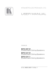
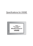
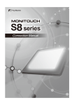
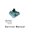
C ATA L O G 2 0 1 2
Control
at your fingertips
innovative control
www.capi2.com
information feedback system
power supply
|
1
innovative control
www.capi2.com
information feedback system
power supply
|
3
Contents
4
|
maritime 2012
www.capi2.com
Capi2 system
|7
Power distribution |9
Navetica
|17
Lighting
|21
Power modules
|29
Why Capi2
|33
Switching |11
Interfaces
|23
|
5
Capi2 Power
Distri bution System
innovative control
Capi2 is a digital power distribution system for motor and sailing
yachts. The system is based on advanced bus technology. It consists of
two main cables [power supply] and a data cable, and replaces traditional cable looms
information feedback system
power supply
Capi2 stands for ‘Communication And
Power In 2 Wires’. The Capi2 power system
was designed for DIY and professional
yacht builders. The system is really easy to
install and maintain, which makes it the
logical choice for yacht builders and marine
fitters.
Benefits for fitters
Faster and more efficient installation means
saving money on materials, time and personnel
No expensive stocks needed; all products can be
delivered immediately
More effective after sales via practical Internet
desktop sharing
Why Capi2?
• The reduced amount of cabling not only
makes the system reliable, but also decreases risks of, for example, fire.
• Nodes are insensitive to vibrations and
are completely encased, which makes
them completely weather-proof.
• Quick error diagnostics using Capi2
software and desktop sharing via the
Internet.
• If a device malfunctions, only node to
which it is connected will shut down, the
rest will continue to operate.
• Multi-configuration possible; a node can
be programmed to have several functions.
Bus system
The nodes and the switchboard are part
• Low power consumption in stand-by
mode: 0.01-0.04mA per node.
of a ring system. All electrical equipment,
such as lights and pumps, are connected to
the nodes. The commands to open or close
a node (to activate equipment) are given by
digital signals.
6
|
maritime 2012
www.capi2.com
|
7
e a sy C o n f i g u r at i o n
Program overview
ship length
1-8 m
6-10 m
1-8 m 6-10 m 10-12 m 13-16 m
Capi2 Touch Screen 3” / -
-
-
-
-
1
1
1
Switch interface 1
2
2
3
4
5
4
5
Monitouch 10.4”
-
-
-
-
1
1
1
1
Bus generator 1
1
1
1
1
1
1
1
1
1
1
1
1
1
1
1
Compact power module
1
2
2
3
-
-
-
-
DC Power node module -
-
-
-
4
5
5
7
DC Power/sensor module -
-
-/1
1
1
2
1
2
AC Relay module for 12V system -
-/1
-
-/1
1
2
-
-
AC Relay module for 24V system -
-
-
-/1
2
2
3
4
With Capi2 Studio® you can program and configure your complete
Capi2 system. Capi2 Studio® is unique and has numerous self-learning
features.
10-12 m 13-16 m
Capi2 panels serie
Capi2 Touch screen 5.7” or
Push-button board 21 keys or
Installation software
Capi2 Studio (easy install) AC/DC Power modules
Lighting modules (LED)
Light control module 1
1
1
1-2
2
3-5
4
Capi2 Studio® contains the latest versions
of all the firmware for Capi2 hardware
nation such as navigation/saloon lights,
products and the software required to
etc.
Configuration software
reprogram the devices. Download the lat-
Multiple loads/group of loads to one
downloadable from the site
est version of Capi2 Studio from the Capi2
switch or single switch for all lights
website to update the firmware on your
6
devices.
The following can be programmed with
Interfaces
NMEA Interface
-
-
-
-
-
-/1
-
Capi2 Studio®
-/1
Victron
-/1
-/1
-/1
-/1
-/1
-/1
-/1
-/1
Universal interface
-/1
-/1
-/1
-/1
-/1
-/1
-/1
-/1
Multiple inputs to create lighting combi-
12V or 24V operation
Digital fuses of the power node modules
3/6/10/13/16 Amp
Talor-made configuration
Timer functions; bilge pump, propane
relays, departure lights
Alarms; defective lamp broken cable,
Acoustic and visual feedback for bilge
pumps
Standby function of loads when system
is shut down; refrigerator and bilge
pumps
Power management priorities with automatic shutdown of low priorities at low
current
Automatic start-up of high priority loads
if digital communication fails
Tank monitoring
high water
Dimmer functions for halogen and several types of LED lights
Momentary/Toggle switch
8
|
maritime 2012
www.capi2.com
|
9
1 + 2
32
1
2
Capi2 Studio
Max. 10 m / 33 feet, 80A
Main feeders: 16 mm2 / AWG 4
Bus cable: 1.5 mm2 / AWG 14
e a sy s o f t wa r e
16-24h
groups of loads
Download Capi2 Studio
Make configuration easy by downloading the Capi2 Studio® software. It contains the latest verDimming zone 1
sions of all the firmware for Capi2 hardware products and the software required to reprogram
Dimming zone 2
the devices. Download the latest version of Capi2 Studio from the Capi2 website to update the
firmware on your devices.
5A fuse
1
A
1
2
3
4
11
12
15
13 14
Dimming zone 1
16
B
17 18
C
D
Dimming zone 4
Dimming zone 2
Dimming zone 3
5 6 7 8 9 10
Start configuration
2
Create a complete setup in 6 steps. After this you will be ready to download the configuration
5A fuse
50A
into the system.
80A
19
20
23
21 22
24
25 26
27
28
29 30
31 32
Step 1 Fill in system settings such as date, project name, setup voltage etc.
33 34
Step 2 Choose your input modules [A]
5A fuse
Step 3 Choose your output modules [B]
CAPI2
B
Dimming zone 3
Step 4 Setup the functionalities of the input and output modules
Dimming zone 4
Step 5 Pull the visual cables [C] between input and output modules
Download the configuration from your computer to the installed Capi2 system. Print configuration for your own administration
Note: the configuration will be stored into the bus generator which is connected to the Capi2
system and can always be uploaded for future changes.
main feeders
DC power node
10 | maritime 2012
B
Bus generator
push-button board
21 keys
S
switch interface 8 key
AC-module
switches
Light Control Module
www.capi2.com
| 11
switch i ng
Control via digital energy-electronics using standard ship cables and
screw terminals makes installation really easy. The switchboards are
designed to withstand the toughest conditions at sea.
Switch interface 8 keys
Backside
Front
21 pushbutton panel
The Capi2 switching panels product group
are supplied with a clear user manual and
contains a comprehensive series of articles
you can, of course, contact Capi2 if you
ranging from traditional switches to ultra-
have any questions or problems with instal-
modern touch screens. The 8-switch inter-
lation.
face enables, for example, the renovation of
existing control panels or dashboards. The
touch screens can display real-time data
Touch Screen 5,7"
and increase the interactivity with your
boat. The screen design and programming
can, if necessary, be completely customised
in accordance with your wishes.
Plug and Play
Touch Screen 3"
The switchboards in this advanced bus system are easy to use and install. No solder-
Clear user manuals
ing or protective cabling is needed, which
reduces the installation time. All products
12 | maritime 2012
www.capi2.com
| 13
Capi2 Touchscreen 3" [art. 100600]
Capi2 Touchscreen 5.7 [art. 100610]
Monitouch Touch Screen 10.4"
[art. 100430]
Push-button board 21 keys [art. 100150]
This Monitouch Touch screen is developed for larger yachts
This is a three inch color touch screen that will control up to
Control up to 50 different loads/groups spread over 5 pages.
six different loads. It includes not only switch functions but
Integration with the newest high precision battery monitors
also alarms for short circuit and broken lamp cable or blown
from Victron Energy.
bulb. The alarm will show the type of alarm/location of node/
name of node and serial number of node, all for very easy fault
findings.
Capi2 panels. The options include a customized overlay.
For indoor use only
Includes functions such as
IP65 front proof
Anti-corrosion
Momentary or toggle switching
Control up to 50 loads/groups
Resistive touch
Timer functions
5 Pages
Anti-reflictive protection glass
Visual and audible warning for low current
Calculate ampere-hours consumed [i.c.w. interface]
Resetting electronic fuses in the nodes
The unit can be mounted in horizontal or vertical position.
Calculate the state of charge of a battery [i.c.w. interface]
Because of the small mounting depth the screen can be easily
Tank monitoring
integrated into nearly any dash panel or console.
Victron battery monitoring, inverter/charger control.
A
A
B
C
J
D E F
Defective cable/lamp indicator
A: 304 / 12
Adjustable backlight and replaceable symbols
B: 231 / 9,1
K
D E F
G
L
I
H
A
D: 216 / 8,5
J
E: 7
/ 0,27
F: 69
/ 2,7
G
D
B
I
E B
K
C
H
Sizes: mm/inch
C: 289 / 11,4
A
B
C
G
The push-button board can be placed parallel with other
and with the possibility to control all 24V and 220V loads.
I
E
F
D
Sizes: mm/inch
D: 70
/ 2.8
H: 4
/ 0.16
L: 7
/ 0.28
Sizes: mm/inch
D 130 / 5,12
H 4,3 / 0,17
L 8
/ 0,32
A: 100 / 3.9
E: 56.6 / 2.2
I: 6
/ 0.24
M: 15
/ 0.59
A 180 / 7,09
E 117 / 4,61
I 20
M 22
/ 0,87
A: 187 / 7.4
D: 171.5/ 6.8
G: 162.5/ 6.4
B: 165 / 6.5
E: 145 / 5.7
H: 138 / 5.4
/ 0,79
B: 81.5 / 3.2
F: 44.4 / 1.7
J: 81.6 / 3.2
B 161 / 6,34
F 89
/ 3,50
J 161 / 6,34
C: 59
G: 2.4 / 0.09
K: 64 / 2.5
C 118 / 4,65
G 2,2 / 0,09
K 125 / 4,92
Technical specifications
Operating voltage:
12V-24V
Storage temp: -30°C/-22°F to 80°C/176°F
Standby power consumption: 5.9mA
Operational temp: -20°C/-4°F to 70°C/158°F
Active power consumption: 28.3mA
Weight: Encapsulation: IP 64
Recommended location: Rain protected area
104g/0.22 lbs
Print board has a coated surface
Ignition protected: NO
front color:
white, black or silver
Operating voltage: Operating voltage: 50
Storage temp:
-30°C/-22°F to 80°C/176°F Standby power consumption: 5,9 mA Operat. temp: -20°C/-4°F to 70°C/158°F Active power consumption: 35 mA Weight: Amount of switches: Encapsulation: 12V-24V
IP 64
Recommended location: rain protected area
500 g/100 Ibs
Print board has a coated surface
Ignition protected: NO
Inrusch current
maritime 2012
20A, 2ms
Active power consumption:
25 W
colour LCD
12 V-24 V
Operational temp:
-4°C/24°F to 50°C/122°F
Weight: 564 g/1.24 lbs
<0,1mA
Print board has a coated surface
100mA
Ignition protected: NO
IP Proof: www.capi2.com
Operating voltage: Active power consumption: 2,5 kg
Ignition protected: 800 x 600 px
J: 109 / 4.3
Weight: Switching: momentary/ Toggle
Visual/ audible alarm:
various options
I: 135 / 5.3
Standby power consumption: yes
various options
F: 18.5 / 0.7
Storage temp: -10°C/-50°F to 50°C/122°F
Coated surface:
Indicator: / 0.4
21 Keys
TFT:
Control button: various options
Resolution:
14 | 24V DC
C: 10
Technical specifications
Technical specifications
Technical specifications
4 or 6
Amount of switches:
H
C
M
Sizes: mm/inch
/ 2.3
J
I
F
L
M
J
IP65 with gasket / IP20 from rear
NO
Splash waterproof
Storage temp: -20°C/4°F to 70°C/158°F
Certifications: EN61000-6-2,
EN61000-6-4, UL 50B, UL1604, CE,
FCC, DNV
| 15
Switch interface 8 keys [art. 100300]
Bus generator
[art. 300100]
d o m o t i c a f o r ya c h t s
C A P I 2 N av e t ica
Capi2 Navetica integrates all electrical systems, devices and equipment
in yachts for increased comfort, convenience, safety, security and energyefficiency.
Every boat needs a bus generator so that digital messages can
Customized switch panels can be built using the 8-key switch
be created.
interface. Toggle or momentary switches can be used.
Dual commands is an option on bigger boats; a parallel set-up
Sizes:mm/inch
with other Capi2 panels facilitates dual commands, e.g. on
the fly bridge or in the living room to control various lighting
A
E
B
options. This switch interface can be used as a main panel on
A: 110 / 4.3
D: 26 / 1.0
B: 89 / 3.5
E: 99 / 3.9
C: 56 / 2.2
F: 38 / 1.5
smaller boats.
Customized indicator panel
F C
D
Use this interface to build customized indicator panels for
navigation lighting, bilge pumps and alarms
Technical specifications
Alarm
This interface can also be used to indicate 8 different open/
Operating voltage: close signals for alarms such as high water, open hatch, open
window etc.
A
E
B
Sizes: mm/inch
C: 56 / 2.2
A: 110 / 4.3
D: 26 / 1.0
B: 89 / 3.5
E: 99 / 3.9
F: 38 / 1.5
F C
D
12V/24V
Screw connector tin-plated
Screw connector
max current: 10A
connection: RS232-screw connection
power outlets:
IP Proof: 13 W
IP64
Computer interface: RS232 or USB/RS232 converter
Storage temp: -20°C/-40°F to 70°C/158°F
Print board has a coated surface
Operat. temp: -4°C/-24°F to 50°C/122°F
Ignition protected: NO
Polarity protection: YES
Weight: Certifications: Weight: 90 g/0.21lbs
You often have to leave your boat unattended in a marina miles away, but you still
92 g/0.21 lbs
need to know whether there is, for exam-
CE, ABYC
ple, enough fuel on board for heating in the
Technical specifications
Operating voltage: 12V-24V
Tin-plated screw connections
8 toggle switches or
4 momentary switches or and 4 led
8 led
8 open/close signals
Led output winter. If there is a storm, it is also certainly
max. 3V
NO
Polarity protection: YES
Weight: 24/7 on-board control
information feedback system
comfort and safety
reassuring to be able to check the situation
Print board has a coated surface
Ignition protection: Features
on board from wherever you happen to be
in the world.
76 g/0.17 lbs
Applications
To build customized panels
Create dual commands on boats
Control various lighting options
16 | maritime 2012
www.capi2.com
| 17
C a p i 2 N av e ti c a
Total co n t r o l o f yo u r b oat . . .
w h e n e v e r and w h e r e v e r
Measuring shore power
Lighting
Battery data
AC/DC power
supply
Climate
control
Wind speed and
direction
Tank levels
GPS position
and history
Alarm
Water
temperature
CCTV
images
Compatible with
smartphone, Ipad, PC and on-board panel PC
Optimal control
Internet - AV - Entertainment
The Capi2 Navetica system continually moni-
A yacht is not complete if it is not fitted with
tors the status of your boat. In an emergency,
good communication equipment. It is impos-
a text message can be sent to you or the
sible to imagine life today without the Inter-
harbour master and you can switch equip-
net and Capi2 supplies a simple yet reliable
ment on and off remotely via a WiFi or 3G connection. An X-box and PlayStation can also
connection.
be installed on board.
Position tracking
A boat’s GPS location is continually read. This
data can also be logged with an adjustable
timer that allows the route that the boat has
sailed to be displayed in Google Maps. This
tracking system is really practical for rented
yachts. A Smartphone or PC can be used to
check where the boat is sailing or at anchor.
Safety
Comfort
For security and monitoring the situation on
Capi2 Navetica gives you control of everything
and around your boat, a sophisticated camera
on board, including, for example, the heating,
system (CCTV) is fitted on board. Live images
air conditioning, interior and exterior lighting
can be viewed remotely via a smartphone
and even the window blinds.
or PC and footage of alarm situations can
Capi2 Navetica radically simplifies operat-
be saved. It is even possible to operate the
required for fitting marine power supply and
ing the equipment you have on board, such
cameras remotely.
control systems.
as a TV, DVD-player, etc. by replacing all the
The camera images can also be displayed on
remote controls with a single unit.
Installation
Capi2 can configure your boat entirely in accordance with your wishes. Capi2 is the market leader in and has the specialist expertise
your on-board TV circuit or on a monitor in
the wheel house. This makes the cameras a
useful aid in navigating and mooring.
18 | maritime 2012
www.capi2.com
| 19
lig h t ing
Capi2 has developed a light control module [LCM] that gives you optimal performance, connectivity and usability. Control and dim your
lights cost-effectively.
More and more LED lights are being introduced on the market. A common problem
is how to control and dim them in a costeffective manner. Capi2 has developed a Light
Full remote control
2 Dimming zones
Control System [LCM] that gives you optimal
Soft start
performance, connectivity and usability.
Direct, digital and analogue dimming
Control and dim your lights cost-effectively.
The LCM can be used in different ways; for
controlling light groups [all type of led lights]
LCM [light control module]
Features
that need to be dimmed or in a existing Capi2
installation. No special expensive thirdparty
Short circuit protection
Advanced hotel switching with multiple
locations
Power width modular (PWM) technology
unit is needed any more. Just connected It to
the information cable (C-2) and the common.
The light control module is a small unit to
which both halogen and several types of LED
lights can be connected and fully controlled. It
can be incorporated into a digital stand-alone
light system or, alternatively, a complete
digital system from Capi2. It is both easy to
install and to program.
20 | maritime 2012
www.capi2.com
| 21
Light Control Module [LCM]
[art. 200900]
Approved suppliers
Capi2 has tested several types of LED lights from different suppliers. The following suppliers have been approved by Capi2
I nte r fac e s
Modern boats contain a large amount of equipment, such as navigation instruments, depth gauges, and automatic steering gear, that each
have their own communication protocols such as NMEA, SeaTalk or
variations of CAN-bus or Modbus.
Technical specifications
LED voltage: 12V-24V
Inductive loads: no
Power outlet, switch input: 2, 1
Remote control: YES
Fuse: Digital 2,5A, blade fuse 4A
Functions: Soft start: YES
Weight: Ignition protected: NO
Dimmers, timers
88 g
Measurements
Sizes: mm/inch
A
A: 122 / 4,8
C: 25 / 1
B: 46 / 1,8
B
C
Capi2 has developed various interfaces that
can communicate with several of these
CANMOD-bus interface
systems. Capi2 interfaces include a NMEA interface, a universal interface, a Victron
Interface and a CAN/MOD bus interface.
All our interfaces are specially designed to
increase the ease of use for our customers. The Capi2 protocol is compatible with
software and interfaces developed by other
manufacturers.
Example scheme
BMV Victron interface
LCM
Dimming zone 1
(Max. 3A)
Dimming zone 2
(Max. 3A)
LCM
DC DISTRIBUTION
NAME
NAME
NAME
NAME
Switch interface
3” Touchscreen
DC Distribution
Main circuit breakers
CAPI2
NMEA interface
5.7” Touchscreen
21 keys panel
Battery
22 | maritime 2012
www.capi2.com
| 23
NMEA interface
[art. 100570]
Capi2 has developed a gateway for interfacing our products to the NMEA 2000 bus. Through this interface can all appliances controlled by Capi2 be monitored and controlled
through a NMEA device (plotter/touch screen).
NMEA 2000
The National Marine Electronics Association (NMEA) has
introduced a standard (NMEA 2000) for data communications
among shipboard electronic devices. The NMEA 2000 network
can accommodate navigation equipment, power generation,
engines and machinery, piloting and steering systems, fire
alarm, and controls.
Technical specifications
Operating voltage:
12V/24V
Weight:
Capi2 Connector: Phoenix 3 pole
Certifications: NMEA Connector:
IP Proof
Binder M12
Printboard
has coated surface:
yes
Ignition protected:
No
Polarity protection:
YES
125 G/0,27 LBS
CE, ABYC, NMEA
IP64
Storage temp:
-20C/-40F to 70C/158F
Operating Temp:
-4C/-24F to 50C/122F
Applications
NMEA plotters, NMEA touchscreens,
CAPI2 and NMEA 2000
Capi2
Touchscreen
Capi2
NMEA 2000
Bus line
24 | maritime 2012
www.capi2.com
| 25
Victron energy and Capi2
Victron BMV interface
[art. 300730]
Victron Can/Mod-bus Interface Art. 300720
Capi2 Nederland BV has entered a partnership with Victron Energy BV as part of
Operate and monitor Quattro’s, Inverters and Inverter/Charg-
the integration of Victron products in its Capi2 power distribution system.
ers using a Capi2 5.7” Touchscreen.
Now Victron Energy equipment is compatible with Capi2 bus systems. This will
Sizes:mm/inch
allow users to operate and monitor Victron Precision Battery Monitors, Quattro’s,
Inverters and Inverter/Chargers using their Capi2 systems.
A
B
E
C
A: 110 / 4.33
D: 30 / 1.18
B: 103 / 4.1
E: 98 / 3.9
C: 47 / 1.9
F: 32 / 1.3
F
D
Technical specifications
Operating voltage
The interface makes it possible to read measurements such
as battery voltage, discharge and charging status. Data can be
displayed in Ampère-hours, (Ah) or in %.
12V/24V
Capi2 Connector Phoenix 3 pole
CAN Connector
MOD connector
Binder M12
RJ45
Printboard has coated surface yes
Applications:
Vicron BMV, Quatro, Multiplus.
A complete set contains the following:
Ignition protected
No
Polarity protection
Yes
Weight
Certifications IP Proof
98 G/0.22 LBS
CE, ABYC
IP64
Storage temp
-20°C/-40°F to 70°C/158°F
Operating Temp
-4°C/-24°F to 50°C/122°F
Applications
• Interface
Vicron BMV, Quatro, Multiplus.
• RS232 kabel.
Sizes:mm/inch
A
E
B
A: 110 / 4.3
D: 26 / 1.0
B: 89 / 3.5
E: 99 / 3.9
C: 56 / 2.2
F: 38 / 1.5
F C
Uninterrupted Current from Victron Energy
D
Power specialist Victron is constantly devising new solutions for power supplies
in extraordinary locations. The company is a leading supplier of self-sufficient
Technical specifications
off-grid systems for the maritime, industrial, automotive, off-grid and rehabilitation markets. Its product range includes sinusoidal inverters, charger/inverters,
Operating voltage: battery chargers, DC/DC converters, switch panels, and
Screw connector:
intelligent Battery Monitor, Global Remote and Blue
Solar Panel products. Victron Energy has earned itself an
enviable and unrivalled reputation in the field of technical innovation, reliability and durability. Its products are
regarded worldwide as the no. 1 professional choice for
self-sufficient electrical power generation.
26 | maritime 2012
12V/24V
tin-plated
Screw connector max current: 10A
Weight: Certifications: 92 g/0.21 lbs
CE, ABYC
connection: RS232-screw connection
Computer interface: RS232 or USB/RS232 converter
power outlets:
Print board has a coated surface
Storage temp: -20°C/-40°F to 70°C/158°F
Ignition protected: NO
Polarity protection: YES
www.capi2.com
IP Proof: 13 W
IP64
Operat. temp: -4°C/-24°F to 50°C/122°F
| 27
CAN/Modbus interface
[art. 300700]
Universal interface
[art. 300740]
Available
first quarter
2012
Available
first quarter
2012
Power modules
Get one step closer to total system integration. The CAN/Mod-
The Universal Interface is Capi2’s multifunctional interface for
bus Gateway from/to Capi2 is an electronic tool that facili-
a total of 4 different applications. Use the Universal Interface
tates two-way communication between CAN-bus or Modbus
to control relays, to switch on/off LED lights, set up alarm indi-
devices and the Capi2 bus.
cators and create smart switching on board your ship. Control
Now nothing stands in the way of using the car-industry phi-
everything that consumes a max. of 1 Amp. Capi2 developed the AC relay module and DC power node modules to
increase the on-board comfort level and safety. These power modules
provide lights, instruments and pumps with the correct voltage so that,
among other things, the risk of overloading is minimised and any malfunctions are made visible immediately.
Set up smart switching
losophy ‘Different bus systems for different functions’.
Control the inverter, charger or air-conditioning in combination with other equipment from a Capi2 touchscreen.
Indicate open/closed alarms
Switch LED lights on/off
Control 220V/110V relays, bow thrusters, windlass or
Install CAN-bus or Modbus based touchscreens with
integrated motor management and control your electrical
remote battery switches.
appliances and lights, which are connected to Capi2.
Sizes:mm/inch
Victron Energy equipment is compatible for use with Capi2
bus systems. It allows users to operate and monitor Quat-
A
B
E
tros, Inverters and Inverter/Chargers using their Capi2 5.7”
Touchscreen. See under Victron CAN/Modbus Interface.
A: 110 / 4.33
D: 26 / 1.02
B: 103 / 4.1
E: 98 / 3.9
C: 47 / 1.9
F: 32 / 1.3
A
B
E
C
F
C
Sizes:mm/inch
A: 110 / 4.33
D: 30 / 1.18
B: 103 / 4.1
E: 98 / 3.9
C: 47 / 1.9
F: 32 / 1.3
F
D
Applications
D
LED lights, light switching, windlass, bow thruster, 220V/110V,
and alarms. Available: first quarter 2012
Applications
DC Power node module and DC Power/sensor module
Technical specifications:
Inverters, chargers, battery monitoring, heating.
Operating voltage
Technical specifications:
Operating voltage
Capi2/Power Connector
Phoenix 3 pole
12V/24V
Weight
Capi2 Connector Phoenix 3 pole
Certifications CAN Connector
IP Proof
Binder M12
MOD connector
12V/24V
RJ45
Printboard has coated surface yes
Ignition protected
No
Polarity protection
Yes
98G/0.22 LBS
CE ABYC
IP64
Power connector max current
10A
Outputs/Inputs
8
Printboard has coated surface yes
Ignition protected
No
Polarity protection
Yes
Weight
Certifications 105G/0.23LBS
CE ABYC
Storage temp
-20°C/-40°F to 70°C/158°F
1-8 switch inputs
IP Proof
1-8 Open/Close input signals Operating Temp
-4°C/-24°F to 50°C/122°F
1-8 Power outputs
Storage temp
-20°C/-40°F to 70°C/158°F
Max current per power output
1 Amp
Max total output
6 Amp
CPM [Compact Power Module]
IP64
One or more ring system(s) consisting of a
For the auto-
red and a black battery cable, and a purple
motive indus-
data cable are fitted to the boat’s battery.
try a compact
The electronically controlled DC power
power module
node modules that provide the lights,
is developed for se-
instruments and pumps with the correct
rial production builders who
voltage are installed in the ring systems.
want to integrate the benefits of a digital
A power node module has 4 outlets. Each
bus system, but at a reasonable price.
outlet has a chip that communicates with
Capi2 developed the AC relay module for
the Capi2 control panel or touch screen
connecting 230V devices. With this module,
and indicates the exact status of on-board
3 different devices can be hooked up, giving
equipment. The power node modules are
you total control of all the electrical power
installed close to power-consuming equip-
consumption on board your boat.
ment to reduce the amount of cabling and
weight.
Operating Temp
-4°C/-24°F to 50°C/122°F
With our free installation software, you can
configure your boat entirely according to
AC Relay module
your wishes. You can, for example, select
the preferred amperage (from 3A to 16A)
for each outlet, create dimmers, timers or
special switching combinations for lighting.
28 | maritime 2012
www.capi2.com
| 29
DC Power node module screw connection
DC Power node module Deutsch connection
[Art. 200100]
DC Power/sensor module screw connection
[art. 200200]
[art. 200300]
DC Power/sensor module
Deutsch connection
[art. 200400]
Contains power nodes that are programmable for 3A/ 6A/
The same module as art. 200100 but with a water tight single
Contains 2 power nodes that are programmable for power
The same module as art. 200300 but with a water tight single
10A/ 13A/ 16A power consumption. In the event of an emer-
connector [Deutsch]. The maximum power is 13A in stead of
consumption and 2 sensor nodes programmable as dimmers,
connector [Deutsch]. The maximum power is 13A in stead of
gency situation, each node can be bypassed using a standard
16A.
floaters, switches, alarms, tank monitoring and timer funtions.
16A.
blade fuse. The nodes are fully potted.
In the event of an emergency situation, each node can be
• 4 Power nodes
A
• 12V-24V
E
• Programmable for 3A/6A/10A/13A/16A
• Screw Connection
B
F
+
-
+ + -
+
-
+
-
+ + -
C
• Bypass for each load with a blade fuse
B: 89 / 3,5
D: 35 / 8,2
• Bypass with a blade fuse
E: 208 / 2,5
• Screw connection
+
-
+ + -
Operating DC voltage: D: 35 / 8,2
+
E: 208 / 2,5
4
Digital fuse: F: 63 / 0,3
3/6/10/13 A
Surge capacity: G
D
Operating DC voltage: Co nnector main feeder
Screw:
Polarity protection: YES
Fully potted: YES
Surge capacity: Power consumption in standby: 0.1-0.4 mA
Electronic system bypass: YES
Ignition protected: NO
Polarity protection: YES
Fully potted: YES
Weight: Fuse: 120A
Weight: 90A /2 ms
Defective cable/lamp indicator: 30mA
375 g/0.83 lbs
Co nnector di gital cable
Screw:
3 mm/0.12 inches/brass
Fuse: 10A
Co nnector to loads
Screw:
Terminal: 4 mm nickel plated
brass/tin-plated
Washer: steel/zinc clear chromate
Fuse:
-
+ + -
+
C: 15 / 1,4
-
D: 35 / 8,2
sizes in mm/inch
max 16A
B
-
+ + -
+
-
+
-
+ + -
Fuse: 375 g/0.83 lbs
Screw:
A: 220 / 8,7
Technical specifications:
B: 89 / 3,5
+
Operating DC voltage: -
D: 35 / 8,2
6 mm/0.24 inches/brass
G
F: 63 / 0,3
Technical specifications
Operating DC voltage: Watertight Deutsch connector
Power outlets: Fuse: Digital fuse: max 13A
12V-24V
4
3/6/10/13 A
Surge capacity: Connecto r main feeder
Screw: 6 mm/ 0.24 inches/brass
Fuse: 120A
90 A/2 ms
Defective cable/lamp indicator: 30mA
Connecto r dig ital cable
Power consumption in standby: 0.1-0.4 mA
Fuse: Electronic system bypass: YES
Ignition protected: NO
Polarity protection: YES
Fully potted: YES
Weight: 375 g/ 0.83 lbs
3/6/10/13 A
Surge capacity: 3 mm/0.12 inches/brass
Co nnecto r to loads
2
Digital fuse: D
10A
12V-24V
Power outlets: E: 208 / 2,5
120A
Fuse: NO
3/6/10/13/16 A
Screw:
Power consumption in standby: 0.1-0.4 mA
YES
6 mm/0.24 inches/brass
+
Co nnecto r main feede r
Co nnecto r digital cable
Ignition protected: Digital fuse: E
90 A/ 2ms
Electronic system bypass: 4
+
F: 63 / 0,3
Defective cable/lamp indicator: 30mA
Technical specifications
Power outlets: -
D
F
12V-24V
Power outlets: -
12V-24V
+
B: 89 / 3,5
E: 208 / 2,5
Technical specifications
B: 89 / 3,5
B
F
-
+ + -
C
CAPI2
A: 220 / 8,7
CAPI2
+
-
A
sizes in mm/inch
E
+ + -
+
F: 63 / 0,3
A
-
B
F
• Polarity protection
D
+
A: 220 / 8,7
CAPI2
• 12V-24V / Programmable for 3A, 6A, 10A, 13A or 16A -
• Polarity protection
sizes in mm/inch
• 2 Power nodes and 2 sensor nodes
C: 15 / 1,4
+
A
E
A: 220 / 8,7
CAPI2
• Standard marine cable for digital information
bypassed using a standard blade fuse.
sizes in mm/inch
Connecto r main feeder
Screw: 6 mm/ 0.24 inches/brass
Fuse: 120A
90 A/2 ms
Defective cable/lamp indicator: 30mA
Connecto r dig ital cable
Power consumption in standby: 0.1-0.4 mA
Fuse: Electronic system bypass: YES
Ignition protected: NO
Polarity protection: YES
Fully potted: YES
Weight: Screw: 3 mm/ 0.12 inches/brass
10A
Connecto r to loads
Watertight Deutsch connector
Fuse: max 13A
375 g/ 0.83 lbs
Screw: 3 mm/ 0.12 inches/brass
10A
L evel measu r ing
0-300 Ω / 0-5 V
Connecto r to loads
Screw:
Terminal: 4 mm nickel plated
brass/tin-plated
Washer: steel/zinc clear chromate
Fuse:
max 16A
L evel measu r in g
0-300 Ω / 0-5 V
30 | maritime 2012
www.capi2.com
| 31
Compact Power Module [CPM]
[ART. 200800]
AC Relay module for 12V
[art. 200500]
Why CAPI2
ENVRIONMENT
Because the Capi2 only has 50% of the amount of cabling of conventional
This power module is specially developed for serial production
builders who want to integrate the benefits of a digital bus
system, but at a reasonable price. At the special request of the
automotive industry, the module was equipped with standard
automotive fuses instead of digital fuses. This means that the
Compact Module must be placed at an accessible location.
systems, its environmental impact is significantly lower. This also provides
The Universal Interface is Capi2’s multifunctional interface
additional advantages, such as a lower total weight and a large reduction in
with total 4 different applications. Use the Universal Inter-
installation time.
face to control relays, to switch on/off LED lights, setup alarm
indications and create smart switching on board of your ship.
Control everything which consumes max. 1 Amp.
Automatic start-up of load when the system is turned on
Alarm with text message indicating location of blown fuse
Automatic shutdown of load when in overload
Setup smart switching
COMFORT
Indicate open/close alarms
Use universal switches and assign dimmer or timer functions to lighting.
Switch on/off LED lights
Alarm with text message indicating location of overload
Leave your boat feeling safer and let the lights switch off automatically only
Control relays such as 220V/110V, bow thrusters, windlass
Multiple languages
when you are no longer on board. Capi2 is easy to operate and gives you total
or remote battery switches.
Multiple switching, including hotel switching
control over all on-board equipment.
LED indication on module indicating which fuse needs
Sizes: mm/inch
replacing
A
Remote control
A: 100 / 4.0
C: 95 / 3.7
B: 160 / 6.3
D: 13.5/ 0.5
SAFETY
Measurements
A
A: 146 / 5,7
Because all installed equipment is digitally fused, the Capi2 increases general
B
Sizes: mm/inch
safety on board. Programmable timer functions, for example, for the windlass
C
C: 30 / 1,2
and gas solenoid valve so that they automatically shut down after a specific
D
B: 92 / 3,6
amount of time.
B
C
Technical specifications
control power: Technical specifications
Operating DC voltage: POWER OUTLETS
Single/H-bridge Fuse 12V
CONNECTION MAIN FEEDER
8/4
ScreW
7 x < 15A
1 x < 30A
Total Current/module
Ignition protected
NO
CONNECTION DIGITAL CABLE
Polarity protected
NO
2 pole connector PHOENIX
Weight
80 A
FusE
300 g
RELAY
Double pole, double throw
Fuse
CONNNECTOR TO LOADS
18 pin. COpper Tin plated 120A
maritime 2012
glass 16A 110V/220V
Ignition protected: Power outlets: Encapsulation:
3
16A
ASSISTANCE
NO
With the supplied software, your boat can be completely programmed to suit
IP65
Weight: your requirements. The desktop sharing function enables remote viewing so we
640 g/1.4 lbs
can give you advice whenever you need it.
AC Relay module for 24V
[art. 200600]
This unit is the same as art. 200500 but with a higher controlpower, 24V in stead of 12V. Available 1st quarter 2012
3A CONSUMPTION
Technical specifications
It is very important that bilge pumps can be activated even when the system
control power: 24V
Fuse type:
glass 16A 110V/220V
Operating AC voltage: 110V-220V
Ignition protected: Power outlets: Encapsulation:
Power outlet fuse: 32 | Fuse type:
Operating AC voltage: 110V-220V
Power outlet fuse: 6MM/ 0,24 inches
Copper tin plated
Max torque 9,6 N
12V
3
16A
Weight: is switched off. Capi2 makes this possible because one power node only uses
NO
0.1 mA in standby mode. A complete installation in a 12-meter yacht only
IP65
uses 0.9 mA in standby mode. For example: a small tiller autopilot uses 40mA 640 g/1.4 lbs
in standby mode.
www.capi2.com
| 33
About Capi2
Capi2
Complies with
94/25EC
89/336/EEC
International standards
Capi2 Nederland BV is based in Brainport
Eindhoven, the smartest region of the world.
We develop and produce the Capi2 distributed
power system and supply to end users and
wholesalers, as well as special applications to
wholesalers.
We are offering a broad range of products, including power
and sensor modules, circuit breakers, panels, touch screens,
fuse boxes, cabling and installation software.
Capi2 is a leading supplier of distributed power systems
ISO 10133
worldwide, mainly to yacht builders and electricians and is
EMC approvals
meant both for serial production and one time build in. With
EN 61 000-6-2
Capi2 modern technology in digital power electronics is cost-
EN 61 000-6-3
effective for 18ft to 80ft boats. It is fully potted to withstand
IEC 60533
harsh marine environments. Capi2 is the first manufacturer to
also produce power distribution systems for smaller boats.
We are committed to ranking among the leaders who drive
the development of new industry standards and groundbreak-
CE approval
ing developments in distributed power systems.
YES
© 2012 Capi2 Nederland BV
All rights reserved
Compliance with
The information provided ABYC: YES
may not be reproduced and/
or published in any
way or by any means (electronic or mechanical), without the prior, explicit
pending
written authorization of
Capi2 Nederland BV. We regret any inconvenience
that errors may cause horeclame en media
wever we are not responsible for printing or typographical errors.
reclame en media
reclame en media
reclame en media
reclame en media
34 | maritime 2012
kemmekoolen
reclame en media
Capi2 Nederland BV
Spegelt 29
5674 CE Nuenen
The Netherlands
Tel: +31 [0]40 - 2847001
Fax: +31 [0]40 - 2834101
mail: [email protected]
w w w . capi 2 . c o m