1
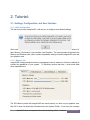
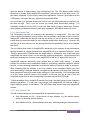
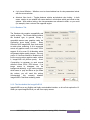
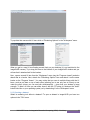
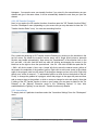
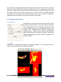
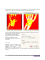
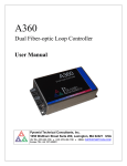
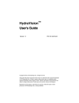
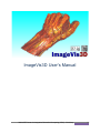
ImageVis3D User's Manual NIH/NCRR Center for Integrative Biomedical Computing (CIBC) - Workshop 1 1. The current state of ImageVis3D Remember : 1. If ImageVis3D causes any kind of trouble, please report this to us! 2. We are still in the process of adding features to the 1.0 release, so please give us your input. NIH/NCRR Center for Integrative Biomedical Computing (CIBC) - Workshop 2 2. Tutorial: 2.1. Settings, Configuration, and User Interface 2.1.1. Initial Configuration The first time you start ImageVis3D, it will ask you to configure some default settings. After selecting `OK', ImageVis3D presents you with the settings window. This consists of 4 tabs: Memory, Performance, User Interface, and Renderer. The most important of these are the Memory and Renderer tabs, which contain compatibility settings to make ImageVis3D work with your graphics card. 2.1.1.1 Memory Tab ImageVis3D contains advanced memory management code to make sure it does not attempt to exceed the capabilities of your system. To effectively perform that task, it must know what those capabilities are. The GPU Memory slider tells ImageVis3D how much memory you have on your graphics card. Mac OS X users can obtain this information from the System Profiler. Linux users can normally NIH/NCRR Center for Integrative Biomedical Computing (CIBC) - Workshop 3 glean the amount of video memory from /var/log/Xorg.0.log. The CPU Memory slider controls the amount of system RAM; ImageVis3D will assume it can access all of this while it runs. For this reason, especially if you're running many other applications, it can be a good idea to set the CPU Memory a bit lower than your system's actual available RAM. It is not so bad if you set these sliders a bit too low, but it can effect performance severely if you set them too high. Thus, if you are unsure, you should utilize conservative settings. It is essentially unheard of for any GPU to have less than 64mb of memory these days; likewise, most systems purchased in the last 3 years have a gigabyte (1024 MB) of memory or more. 2.1.1.2 Performance Tab The Performance tab lets you customize the interactivity of ImageVis3D. The Open files without verification checkbox is off by default, and it is probably a good idea to leave it as such. ImageVis3D verifies that the data you load are not corrupt, so you can be sure you are viewing exactly what you saved last week (or your colleague saved before sending you). However, this process can be slow, and so if you are opening the same file repeatedly it can be nice to disable that check. The four sliders allow control of ImageVis3D's interactivity at the expense of raw performance. Minimal framerate is a target framerate that ImageVis3D will try to maintain at all times. Active Timeslice and Inactive Timeslice have the largest effect on interactivity; they control how often ImageVis3D will check to see if you are changing rendering parameters. Larger timeslices will lower total rendering time, but may cause ImageVis3D to feel as if it `lags' behind your input. ImageVis3D achieves interactivity using multiple level of detail (LOD) settings. A typical scenario for scientists using visualization software is configuring a particular viewpoint, transfer function, or other rendering parameters such that the feature of interest is visible or prominent. While interacting with the software, it can be a nuisance to do a complete render every time some small setting is changed, because a complete render can take quite some time, and many more changes will need to be made before settling on a `final' rendering. LOD techniques allow us to do a quick `preview' render in this scenario, so the user may get an idea of how the completed render will look without committing to the time required for a full render. To take advantage of this, ImageVis3D monitors how long it has been since the user changed a rendering parameter. If it has been `long enough', then ImageVis3D will load and render a higher resolution portion of the dataset. The LOD Delay slider controls how long ImageVis3D will wait. 2.1.1.3 User Interface Tab This tab contains settings for what ImageVis3D will remember across runs. Save Workspace on Exit – Saves the set of open windows, e.g. the transfer function editors, or rendering options windows. Save Window on Exit – Which windows were open, rendering settings in those windows. NIH/NCRR Center for Integrative Biomedical Computing (CIBC) - Workshop 4 Lock cloned Window – Whether or not a cloned window has its view parameters locked with the source window. Absolute View Locks – Toggles between relative and absolute view locking. In both cases, rotation in one window will cause rotation in all windows which are locked to that window. With relative locking, the view parameters are allowed to differ, so you could (for example) view a volume from opposite angles. 2.1.1.4 Renderer Tab The Renderer tab contains compatibility and quality settings. The Render Method selects the renderer type; in general, Slicing is compatible across more graphics cards, but Raycasting gives better quality. Blend Precision tells ImageVis3D how much detail to retain when rendering; 8 bit is supported across all graphics cards, but recent GPUs support 16 bit or even 32 bit blending, which will generate higher quality images. Use only power of 2 textures should be enabled on all but the most modern graphics cards; without it, ImageVis3D will perform poorly. Avoid Compositing is necessary to work around defects in some GPUs / GPU drivers. If an image seems to disappear into the background arbitrarily, or you notice polygons which seem to `pop' and flicker as you rotate the volume, you will need this setting. Unfortunately this currently disables ImageVis3D's ClearView rendering mode. 2.1.2. The Idea behind the ImageVis3D UI ImageVis3D has a very flexible and highly customizable interface, so let us first explore the UI. When you open ImageVis3D all you see is an empty canvas: NIH/NCRR Center for Integrative Biomedical Computing (CIBC) - Workshop 5 To populate that canvas with UI items click on "Rendering Options" in the "Workspace" menu. What you get is a new UI item floating around freely on your desktop (it is not restricted to the ImageVis3D canvas). Try to drag this Item to the borders of your ImageVis3D window and you will see that it attaches itself to the borders. Now , open a second UI item from the "Workspace" menu (say the "Progress viewer") and also attach that to a border. Next, detach the "Rendering Options" item and attach it on the same border as the "Progress Viewer". You may notice that you can do multiple things with the UI items, such as put them on top of each other (allowing you to see only one at a time) or one under the other (where you can see both simultaneously -- given that your window is large enough). To hide a UI item you can either close it with the "X" button (or whatever the "close" button looks like on your operating system) or by deselecting it in the "Workspace" menu. 2.1.3 Opening a dataset What's a rendering tool without a dataset? To open a dataset in ImageVis3D you have two options in the "File" menu: NIH/NCRR Center for Integrative Biomedical Computing (CIBC) - Workshop 6 "Load Dataset from File" and "Load Dataset from Directory": the first option loads datasets stored in a single file or files with detached headers (e.g. nrrd, raw, uvf, etc.) while the second menu item opens an entire directory, analyzes the files in that directory, groups them into stacks, and lets you open those stacks (e.g. images, DICOM). Now let us open the "c60.uvf" dataset from the data directory. Use the "Load Dataset from File" menu item and point it to the c60.uvf in the data directory on your stick (or on the desktop on our machines). You should see an image like this one (maybe not as colorful but similar): Play around a little with the dataset, for example by changing the size of the window. Left click and drag in the window to rotate the dataset, right click and drag to move it and use the mousewheel to zoom in or out. Now hit space to switch to 2x2 mode and you should see something like this: NIH/NCRR Center for Integrative Biomedical Computing (CIBC) - Workshop 7 In this mode you can hit space again over any of the four sub-windows to enlarge that window. Using the mouse over the 3D will behave just like with the large view, while using the mousewheel over the small views scrolls through the slices. Try to hit "x" and "y" over the slice views to flip the x- and y-Axes. “m” will switch between the slice view and a maximum intensity projection. Next, let us load another dataset, this time pick the "tooth.uvf" file. In ImageVis3D you do not need to close the c60 view as it can handle arbitrarily many windows (well actually only up to 232 = 4,294,967,296 but that should be sufficient for most users). Now also play with the tooth dataset. You can also select "Clone current view" from the view menu to create another view to the same dataset. 2.2 Transfer Functions 2.2.1. 1D Transfer Functions Now let us change the way the dataset is rendered, first by playing with the 1D transfer function. First open the "1D Transfer function Editor" from the "Workspace" menu. Now right click and drag the mouse in the black box and watch the dataset change. Now left click and draw into the box and see how you can fine tune your transfer function. The color channels to modify are selectable on the left, and the slider on the right controls the scale of the NIH/NCRR Center for Integrative Biomedical Computing (CIBC) - Workshop 8 histogram. You can also save your transfer function; if you store it in the same directory as your dataset and give it the same name, it will be automatically loaded the next time you open the dataset. 2.2.2. 2D Transfer Functions Next, let us explore the 2D transfer functions, therefore open the "2D Transfer function Editor" from the "Workspace" menu (depending on your screen size you may also want to close the "1D Transfer function Editor" now). You now see something like this: First, switch the rendering to 2D Transfer function Rendering by clicking on the checkbox in the top left corner. By default the transfer function starts with a single quad (unless a premade function was loaded automatically). Now select the "Quadrilateral" in the selection box on the left, and shift + left click (hold the shift key while left clicking and dragging the mouse) in the black box on the right to move the quad around. Use Ctrl + left click to scale the quad and Ctrl + Shift + left click to rotate it. Now, use a `simple' left click to move the nearest vertex (yellow) of the quad or the endpoints of the gradient (green). Right click to add a new vertex to the closest edge of the polygon (note how the name of the polygon changes on box to the left). Right click directly on a vertex to remove it. To add another quad or a circle click on the buttons to the left. Finally, to change the gradient of a polygon, select that polygon in the upper left pane and then add or remove stops to the gradient, or click on a stop to change its color and opacity. Note that if editing of the 2D Transfer function is slow on your system you may want to switch to the "On Release" or the "Manual" Execution mode in the "Rendering Options" UI item. Also enable/disable the "lighting" to see the unlit / Transfer function only dataset. 2.2.3. Isusurfacing To simply look at a particular isosurface select the "Isosurface Settings" from the "Workspace" menu. NIH/NCRR Center for Integrative Biomedical Computing (CIBC) - Workshop 9 First, enable the Isosurfacing with the checkbox and then move the slider to select a specific isovalue. Use the "Choose Color" button to change the color of your isosurface, select a dark blue. Now, enable the "ClearView" technology by clicking on the second checkbox. Now you can select a second isovalue. Next move your cursor over the 3D view of you dataset and hold the shift key. As you can see the "ClearView lens" moves over your data. To change the appearance of the ClearView lens use the three sliders on the bottom. 2.3 Rendering Features 2.3.1. Rotations ImageVis3D can generate a set of images from a 360° rotation around the volume of interest. To do this, select the Recorder from the Workspace menu. The filename listed gives both the format and base name for the generated image files; in the example here, ImageVis3D will generate capture0.png, capture1.png, etc. Click the Capture button and a dialog will appear which queries for the number of images. Note that the images will always represent a 360° rotation, regardless of the number of images. 2.3.2. MIP ImageVis3D can also render MIP images, including MIP rotations. To use this feature, first hit `space' to get a 2x2 panel view of different viewpoints. NIH/NCRR Center for Integrative Biomedical Computing (CIBC) - Workshop 10 Then hover your mouse over the plane you are interested in, and hit `space' again to make that projection the only active one. Finally, hit `m' to switch into MIP rendering mode. You can also generate MIP rotations by using the Recorder window, as shown earlier. When selecting capture, you will be presented with some extra configuration options. Orthographic Projection is probably the projection most people use when generating MIP rotations. Stereo creates stereo MIPs. 2.3.3. Stereo ImageVis3D can also generate stereo renderings, suitable for viewing using anaglyph (“3D”) glasses. Using ImageVis3D in this mode will give the illusion of three dimensional volumes. Use the Workspace | Stereo menu to enable stereo rendering. NIH/NCRR Center for Integrative Biomedical Computing (CIBC) - Workshop 11