1
Usser’s Manual IA
A-F
FEMesh
h
Version 1.0
0 MIMX Laborato
ory Center for Computer Aided Dessign Engineering Ressearch Facility The University o
of Iowa Iowa City, IA www.ccad.uiow
wa.edu/mimx/IA
A‐FEMesh August 2008 IA-FEMesh
IA-FEMesh
Version 1.0 User’s Manual
i | I A ‐ F E M e s h IA-FEMesh
Copyright and Permission Notice Copyright © 2008 MIMX, The University of Iowa All rights reserved. Permission is hereby granted, free of charge, to any person obtaining a copy of this document (the "Document"), to deal in the Document without restriction, including without limitation the rights to use, copy, distribute, and/or to permit persons to whom the Document is furnished to do so, subject to the following conditions: This copyright and permission notice shall be included in all copies or substantial portions of the Document. THE DOCUMENT IS PROVIDED "AS IS", WITHOUT WARRANTY OF ANY KIND, EXPRESS OR IMPLIED, INCLUDING BUT NOT LIMITED TO THE WARRANTIES OF MERCHANTABILITY, FITNESS FOR A PARTICULAR PURPOSE AND NONINFRINGEMENT OF THIRD PARTY RIGHTS. IN NO EVENT SHALL THE AUTHORS, CONTRIBUTORS OR COPYRIGHT HOLDERS BE LIABLE FOR ANY CLAIM, OR ANY SPECIAL INDIRECT OR CONSEQUENTIAL DAMAGES, OR ANY DAMAGES WHATSOEVER RESULTING FROM LOSS OF USE, DATA OR PROFITS, WHETHER IN AN ACTION OF CONTRACT, NEGLIGENCE OR OTHER TORTIOUS ACTION, ARISING OUT OF OR IN CONNECTION WITH THE DOCUMENT OR THE USE OR OTHER DEALINGS IN THE DOCUMENT. ii | I A - F E M e s h
IA-FEMesh
Acknowledgements IA‐FEMesh was an ambitious undertaking that required the contribution of a myriad of talented and dedicated individuals. The Musculoskeletal Imaging, Modeling, and Experimentation (MIMX) Program at The University of Iowa consists of a multidisciplinary team of faculty, staff, and students from the Departments of Biomedical Engineering, Orthopaedics and Rehabilitation, and Radiology. Accordingly, I would like to acknowledge several individuals whose assistance and perseverance made IA‐FEMesh possible. Two individuals were indispensible in the development of this work. Kiran Shivanna, PhD. and Vincent Magnotta, Ph.D. spent countless hours coding and re‐coding to meet the goals of IA‐FEMesh. I would also like to acknowledge several individuals who played vital roles in the development and evaluation of the software, as well as editing the manual for consistency: Nicole Kallemeyn, M.S., Nicole DeVries, M.S., Srinivas Tadepalli, M.S., Ritesh Bafna, M.S., Anup Gandhi, B.S., Jacalyn Grosland, M.S., Mary Beth Russell, M.S., Kristin Brandt, and the students enrolled in the Fall 2007 offering of 051:157 Intro to Applied Biomedical FE Modeling. I am indebted to each of these individuals for their contributions and unwavering support of IA‐FEMesh. N.M. Grosland The MIMX Program gratefully acknowledges financial support provided by awards R21EB001501 and R01EB005973 from the National Institute of Biomedical Imaging and Bioengineering, National Institutes of Health. iii | I A - F E M e s h
Table of Contents
Table of Contents 1 Introduction to IA‐FE Mesh ............................................................................................................................. 1 1.1 Overview ............................................................................................................................................................. 2 1.2 About this Manual .............................................................................................................................................. 2 1.2.1 Organization of the Document .................................................................................................................... 2 1.2.2 Conventions Used Throughout the Document and Software ...................................................................... 2 1.3 Installing and Running IA‐FEMesh ...................................................................................................................... 3 2 Interfacing with IA‐FEMesh ............................................................................................................................. 5 2.1 Overview ............................................................................................................................................................. 6 2.2 The Main Toolbar ................................................................................................................................................ 6 2.2.1 Application Settings .................................................................................................................................... 7 2.2.2 View Settings ............................................................................................................................................... 8 2.3 The View Panel ................................................................................................................................................... 9 2.4 The Command Panel ........................................................................................................................................... 9 2.5 The Object Manager ......................................................................................................................................... 10 2.5.1 Viewing/Activating an Object ................................................................................................................... 10 2.5.2 Naming Convention ................................................................................................................................... 10 2.5.3 Adjusting the Display Properties of an Object ........................................................................................... 11 2.6 The Tabbed Panels ............................................................................................................................................ 13 2.6.1 Loading/Saving/Deleting an Object .......................................................................................................... 13 2.6.2 Exporting a File in ABAQUS Format (.inp) ................................................................................................. 13 2.6.3 The Importance of the Collapsed Frame ................................................................................................... 13 2.6.4 Apply / Cancel an Operation ..................................................................................................................... 14 3 IA‐FEMesh Tutorial ........................................................................................................................................ 15 3.1 Example: Creating a mesh of an anatomic structure ....................................................................................... 16 4 The Image Panel ............................................................................................................................................ 29 4.1 Overview ........................................................................................................................................................... 30 4.2 Image Tab Ø Load ............................................................................................................................................. 30 4.2.1 Supported Image File Formats .................................................................................................................. 30 iv | I A ‐ F E M e s h 4.3 Interacting with the Image ............................................................................................................................... 30 4.4 Image Tab Ø Delete .......................................................................................................................................... 31 5 The Surface Panel .......................................................................................................................................... 32 5.1 Overview ........................................................................................................................................................... 33 5.2 Load/Save/Delete a Surface ............................................................................................................................. 33 6 The Block(s) Panel ......................................................................................................................................... 34 6.1 Overview ........................................................................................................................................................... 35 6.2 Block(s) Tab Ø Create ....................................................................................................................................... 35 6.2.1 Create block from surface bounds, ............................................................................................................ 35 6.2.2 Create block manually ............................................................................................................................... 35 6.3 Block(s) Tab Ø Build/Edit .................................................................................................................................. 36 6.3.1 Building Block Operations Toolbar ............................................................................................................ 37 6.3.2 Rolling Back / Forward a Building Block Structure .................................................................................... 38 6.3.3 Working with a Building Block Sub‐Structure............................................................................................ 38 6.4 Block(s) Tab Ø Delete ....................................................................................................................................... 39 7 The Mesh Panel ............................................................................................................................................. 40 7.1 Overview ........................................................................................................................................................... 41 7.2 Mesh Tab Ø Assign/Edit Mesh Seeds ............................................................................................................... 41 7.2.1 Global Mesh Seed Assignment .................................................................................................................. 41 7.2.2 Local Mesh Seed Assignment .................................................................................................................... 42 7.3 Mesh Tab Ø Create ........................................................................................................................................... 44 7.3.1 Volumetric Mesh ....................................................................................................................................... 44 7.3.2 Surface Mesh ............................................................................................................................................. 45 7.3.3 Node/Element Numbering and Labels ...................................................................................................... 45 7.4 Mesh Improvement .......................................................................................................................................... 45 7.4.1 Laplacian Smoothing ................................................................................................................................. 46 7.4.2 Interior Node Interpolation Methods ........................................................................................................ 46 7.5 Mesh Tab Ø Renumber Nodes/Elements ......................................................................................................... 46 8 The Quality Panel .......................................................................................................................................... 47 8.1 Overview ........................................................................................................................................................... 48 8.2 Quality Tab Ø Evaluate / Display Mesh Quality ................................................................................................ 49 8.2.1 Quality Metrics: ......................................................................................................................................... 49 v|I A - F E M e s h
Table of Contents
8.2.2 A Mesh Quality Summary Report .............................................................................................................. 50 8.2.3 Quality Display Options ............................................................................................................................. 51 8.3 Quality Tab ØMesh Improvement .................................................................................................................... 52 9 The Materials Panel ....................................................................................................................................... 53 9.1 Overview ........................................................................................................................................................... 54 9.2 Materials Tab Ø User‐Defined .......................................................................................................................... 54 9.2.1 Establishing Element Set Definitions ......................................................................................................... 54 9.2.2 Element Set Selection Toolbar Capabilities ............................................................................................... 56 9.3 Materials Tab Ø Image‐Based .......................................................................................................................... 57 9.3.1 Binning Material Property Assignments ................................................................................................... 58 9.4 Materials Tab Ø Display Material Properties ................................................................................................... 59 10 The Load/BC Panel ...................................................................................................................................... 60 10.1 Overview ......................................................................................................................................................... 61 10.2 Load/BC Tab Ø STEP ‐ Load/BC Assignments ................................................................................................. 62 10.2.1 Establishing Node Set Definitions ............................................................................................................ 62 10.2.2 Node Set Selection Toolbar Capabilities .................................................................................................. 64 10.2.3 Assigning a Descriptive STEP Subheading ............................................................................................... 65 10.2.4 Assigning Load / Boundary Conditions .................................................................................................... 65 10.2.5 Displaying the Load/Boundary Conditions .............................................................................................. 65 10.2.6 Assigning *STEP Definitions .................................................................................................................... 66 10.2.7 Multiple Step Analysis ............................................................................................................................. 66 Appendix I: Building Block Operations ‐ Examples ............................................................................................. 67 Appendix II: Element/Node Set Selection ......................................................................................................... 76 Appendix III: Mesh Examples ............................................................................................................................ 81 INDEX ............................................................................................................................................................... 85 vi | I A - F E M e s h
Table of Contents
Introduction to IA-FEMesh
1 Introduction to IA‐FEMesh Introduction to IA‐FEMesh 1|I A - F E M e s h
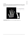
1.1 Overview Finite element (FE) analysis is a valuable tool in musculoskeletal research. The demands associated with mesh development, however, often prove daunting. In an effort to facilitate anatomic FE model development we introduce IA‐FE Mesh (Iowa FE Mesh), a freely available software toolkit. IA‐FEMesh employs a multiblock meshing scheme aimed at hexahedral mesh generation. An emphasis has been placed on making the tools interactive, in an effort to create a user friendly environment. The goal is to provide an efficient and reliable method for model development, visualization, and mesh quality evaluation. While these tools have been developed, initially, in the context of skeletal structures, they can be applied to a virtually endless number of modeling applications (see Appendix III: Mesh Examples). 1.2 About this Manual 1.2.1 Organization of the Document The IA‐FEMesh User’s Manual is divided into four distinct sections. The first section (Chapter 2) details the individual components of the graphical user interface and how they contribute to the meshing process. Chapter 3 steps the user through a tutorial aimed at meshing a proximal phalanx bone of the human hand (Note: a representative surface (index_proximal.stl) and the corresponding image data set (CT_hand.img.gz) may be downloaded from the IA‐FEMesh web site (www.ccad.uiowa.edu/mimx/IA‐FEMesh). Chapters 4 – 10 detail the individual tabbed panels (Image, Surface, Block(s), Mesh, Quality, Materials, and Load/BC) paramount to the meshing process. These panels were designed to step the user, from left to right, through the mesh development process. Lastly, a series of examples are provided in the Appendices detailing some of the capabilities of IA‐
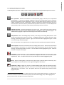
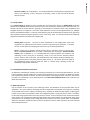
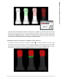
FEMesh, namely the Building Block editing operations and Node/Element selection capabilities. 1.2.2 Conventions Used Throughout the Document and Software The following represent the conventions used throughout this document. Ø Arrows are used to represent cascading from a Tab to a Panel main menu selection. Bold Tab/Panel selections, cursor selections, and actions throughout the document are highlighted in bold text. Colors Colors are used throughout the Building Block editing operations to highlight various states of a given component (i.e., vertex, edge, face). We adopted the colors of a traffic signal to signify an active component (green), a stationary component (red), and with those highlighted in yellow, proceed with caution. 2|I A - F E M e s h
Introduction to IA-FEMesh
1.3 Installing and Running IA‐FEMesh Before installing IA‐FEMesh, you must first download either IA‐FEMesh binaries or source code. IA‐FEMesh is available on multiple platforms. We currently offer pre‐built binary versions for Microsoft Windows®, Mac OS X, and Linux based systems. Windows® Download the windows installer from the IA‐FEMesh Download web site (note: a ZIP archive is also available, this may be preferable for users who do not have administrative access to their machine). Save the installation executable to disk. Run the application from the directory to which it was saved. Follow the prompts to configure the installation of IA‐FEMesh. Once the installation is complete, an IA‐FEMesh submenu will appear in the Window® Start Menu. Should you choose the archive, simply extract the distribution from the download; the application is located in the IA‐FEMesh‐1.0.0/bin folder. Note, IA‐FEMesh is dependent on the library files in this directory and the Tcl/Tk libraries in the IA‐FEMesh‐1.0.0/lib directory. Linux Download the precompiled binaries for the appropriate platform (versions are available for both 32 and 64 bit architectures). Once downloaded, extract the distribution using the tar command (e.g., tar xzvf IA‐FEMesh‐
1.0.0‐Linux32.tar.gz). Note: the executable may be installed either locally or system wide. The executable will be located in the bin directory created during the file extraction process. Consequently, to run IA‐FEMesh from the command prompt, you will need to at add the directory housing the IA‐FEMesh executable to your PATH environmental variable (i.e., path of the bin directory). For bash shell, this can be done using the command, % export PATH=${PATH}:/install-path/IA-FEMesh-1.0.0/bin
where ‘install‐path’ is the directory where you unpacked the program. This can be added to your .bashrc file to make this addition each time you login. For the csh, the following command needs to be run or added to your .cshrc file. % setenv PATH ${PATH}:/install-path/IA-FEMesh-1.0.0/bin
You can then execute the program by typing the following at the command prompt: % IA-FEMesh
Macintosh Download the IA‐FEMEsh‐1.0.0.dmg file. Simply Double click on the filename to extract the installation package. The installation package will guide you through the software installation process. The software, once installed, will reside in installdir/usr/bin. Double click on the IA‐FEMesh application in that directory to start the program. 3|I A - F E M e s h
Introduction to IA-FEMesh
Building IA‐FEMesh If you plan to compile IA‐FEMesh, you must first, download and install CMake, the cross‐platform build system (http://www.cmake.org/HTML/Download.html). Configure and build the following libraries using CMake. VTK (http://www.vtk.org/get‐software.php) version 5.2 Build with VTK_TCL_WRAPPING ON ITK (http://www.itk.org/HTML/Download.htm) version 3.6 KWWidgets – (http://www.kwwidgets.org/Wiki/KWWidgets/Download) You will need to download the cvs version with the tag ‘Slicer‐3‐2’ cvs ‐d:pserver:[email protected]:/cvsroot/KWWidgets co –r Slicer3‐2 KWWidgets Tcl/Tk Version 8.4 Pre‐built versions of the libraries are available from Active State (http://www.activestate.com/downloads/index.mhtml) You can also download the source code from Sourceforge and build this from source (http://sourceforge.net/project/showfiles.php?group_id=10894) Tcl/Tk does not build using Cmake. Instead you will have to follow the platform specific steps for building. For Linux and Macintosh builds, you will run the configure script in the unix directory. This will generate make files for building the software. Under Windows, a solution file exists in the win directory that can be used to build the software. Once these are created, configure IA‐FEMesh using CMake and specify the locations of the ITK, VTK, and KWWidgets. Once the make file, or solution file, is generated you are ready to build the software. The executables will be located in the bin directory of the build tree. 4|I A - F E M e s h
Introduction to IA-FEMesh
Interfacing with IA-FEMesh
2 Interfacing with IA‐FEMesh Interfacing with IA‐FEMesh 5|I A - F E M e s h
2.1 Overview The IA‐FEMesh interface consists of a Main Toolbar, the View Panel, and a Command Panel which consists of an Object Manager and a series of Tabbed Panels. The following introduces each of these basic components. 2.2 The Main Toolbar The most notable menu on the Main Toolbar is the View Menu. The View Menu houses the Application and View Settings. 6|I A - F E M e s h
Interfacing with IA-FEMesh
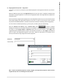
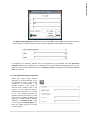
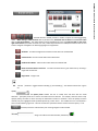
2.2.1 Application Settings Interface Settings Disable/enable the settings such as balloon help, etc. The user‐specified settings will be retained when the program is restarted. The Interface Settings also provide a drop down menu (Position of view panel) to assign the View Panel to the left or right of the interface. IA‐FEMesh Settings – Autosave Work The objects populating the Object Manager will be saved to the working directory by default every 5 minutes, unless specified otherwise. (i.e., directory: IA‐FEMesh‐AutoSave‐date). Average Element Length By default, the initial mesh seed assignments are based on an element edge length of 1. The user is afforded the option of resetting this default length. ABAQUS Material Property Precision The user may adjust the number of significant digits with which the image‐based material properties are written to the .inp file. 7|I A - F E M e s h
Interfacing with IA-FEMesh
Interfacing with IA-FEMesh
2.2.2 View Settings The Colors frame enables the View Panel background and text color to be changed, while the View frame houses a collection of icons used to manipulate or capture a view: Predefined views based on the six faces of a cube. Each triad indicates the orientation of this imaginary cube with the view window. Perspective view. Parallel View Rescale, or autofit, the view to fill the window. Capture/save a screen shot Toggles view of the axes 8|I A - F E M e s h
2.3 The View Panel The View Panel facilitates the interactive nature of building a Block structure, Mesh generation and improvement, in addition to establishing Node and Element Set definitions. Mouse Based Navigation: Zoom, Rotate, and Pan The following actions are available for interactively manipulating an object using the mouse (assumes a right‐
handed mouse). • To zoom in and out, hold the right mouse button and drag the mouse up and down, or if available scroll the middle mouse wheel. • To rotate an object, hold the left mouse button and drag • To pan, hold the center mouse button (or wheel) and drag the object. 2.4 The Command Panel The Command Panel consists of the Object Manager and a series of Tabbed Panels (i.e., Image, Surface, Block(s), Mesh, Quality, Materials, and Load/BC). 9|I A - F E M e s h
Interfacing with IA-FEMesh
Interfacing with IA-FEMesh
2.5 The Object Manager 2.5.1 Viewing/Activating an Object As an object is loaded/created, an identifier is assigned and automatically populates the Object Manager. The Object Manager facilitates control over the visibility and appearance of the individual components/objects (i.e., image, surface, blocks, and mesh). The checkbox preceding the object name toggles the visibility of the object (the default check is visible). A single visible object of a given type (e.g., building block) implies that the object is active for building/editing/manipulation. As a result, these checked objects will automatically populate the collapsible frames throughout the tabbed panels as the default, or active, object. If two objects of the same type are checked (i.e., visible in the view panel), the active object will be considered that listed first in the Object Manager. If no object of a particular type is checked, and is required for a particular task (i.e., building block and/or surface for a mesh definition), then the last object in the list (for that particular type) will be assigned as the default object. This holds true throughout the program for images, surfaces, building blocks, and mesh definitions. If viewing multiple objects of a particular type, the object of interest may be directly activated within the collapsed frame (it is advisable to expand the frame to ensure that the appropriate object, or combination thereof, is active). 2.5.2 Naming Convention The naming convention used throughout IA‐FEMesh uses as its foundation the surface filename. As objects are created/edited, their identifier assumes the following format surface filename_last operation_# times a particular operation has been performed. For example, a surface named index_proximal.stl has been loaded. Thereafter, a building block is created manually. The building block is assigned the identifier index_proximal _BBm‐1. A series of building block editing operations follow such that the building block is subdivided (index_proximal_Split‐1), a block is added (index_proximal _Add‐1), followed by a second subdivision (index_proximal_Split‐2). 10 | I A - F E M e s h
Interfacing with IA-FEMesh
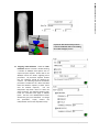
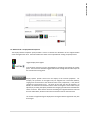
2.5.3 Adjusting the Display Properties of an Object Clicking on the name of an object within the Object Manager will launch a window (as illustrated). This window provides settings to control the appearance of the selected object. The drop down menu labeled Representation provides the options of Surface/Solid and Wireframe viewing, in addition to a combination of the two for a finite element mesh. Moreover the user has control over both the Fill and Outline colors, as well as the opacity of the object. Adjusts the opacity/transparency of a geometric entity. The opacity value ranges between 0 and 1. An opacity of 1 (the default) means the dataset is completely opaque. An opacity of 0 means the dataset is completely transparent. Adjusts the line width of a wireframe representation. 11 | I A - F E M e s h
Property assignments specific to the mesh definitions: Mode: Allows the user to switch between the Complete Mesh and specific Element Sets When Element Sets is selected, the window is populated by the current element set definitions. The checkboxes are used to toggle the visibility of the set. To change the visual appearance of a given set, highlight the set label by clicking on the name. Thereafter, in addition to the aforementioned properties, the user has control over the size of the elements. Element Size (%): Changes the volume of the elements, allowing the user to shrink the element size throughout the mesh. 12 | I A - F E M e s h
Interfacing with IA-FEMesh
Interfacing with IA-FEMesh
2.6 The Tabbed Panels The individual panels were designed to step the user, working from left to right, through the mesh development process. Each panel houses a main drop down menu button, consisting of a series of actions (i.e., Create, Load, Save, etc.) specific to that tab. Chapters 4 – 10 detail the functionalities afforded by each of the tabbed panels. 2.6.1 Loading/Saving/Deleting an Object A number of the actions throughout the panels perform similar tasks for their respective objects. For example, to load a given object (Image, Surface, Block, Mesh), select Load from within the corresponding panel (e.g., to load an image, select Load from the drop down menu within the Image panel). Unless noted otherwise, this also holds true for deleting and saving an object. Saving the Block Structure as well as the Mesh throughout the mesh generation process is highly advised; namely after building the block structure, constructing/improving the mesh, as well as material property and load/boundary condition assignment. Note: All files are saved in VTK format (.vtk). 2.6.2 Exporting a File in ABAQUS Format (.inp) The Mesh, Quality, Materials, and Load/BC panels each afford the user the ability to Export the Mesh definition in ABAQUS file format (.inp). In addition to the input deck (filename.inp) specified by the user, an additional file (filename_input) is created to be read by the main file (i.e., *INCLUDE, INPUT=filename_input). This file accommodates the node and element definitions, in addition to the node and element sets. The image‐based material property assignments are also housed in this file. 2.6.3 The Importance of the Collapsed Frame In addition to the commonality of the main drop down menu, each tab houses a collapsed frame, which accommodates the objects contributing to a given task. For example, both a surface and building block structure contribute to a mesh definition. Consequently, within the Mesh panel’s Create option, resides a Surface & Building Block frame. As described in §Viewing/Activating an Object, the menus will be populated automatically depending on the objects denoted as active via the Object Manager. The user also has the option of activating a particular object by selecting it directly from the drop down menu. 13 | I A - F E M e s h
2.6.4 Apply / Cancel an Operation Lastly, the Apply and Cancel buttons act to perform the given action and to abandon the operation and return to the main menu button, respectively. Note, while a panel is in use, all other panels are deactivated. Cancel must be invoked to change between the tabbed panels. 14 | I A - F E M e s h
Interfacing with IA-FEMesh
IA-FEMesh Tutorial: Proximal Phalanx Bone
3 IA‐FEMe
esh Tutorial IA-FE
EMesh Tutoria
al:
Proximal Phalanx Bo
one 15 | T u t o r i a l
3.1 Example: Creating a mesh of an anatomic structure Anatomic models initiating with an image dataset (i.e., CT / MR) are often processed to yield a 3D triangulated surface representation of the structure(s) of interest. IA‐FEMesh assumes these surfaces form the foundation for the structural geometry, while a series of building blocks are used to establish the mesh. You will initiate the model by loading the surface representation of the bone of interest. A building block, or series of blocks, will be constructed, assigned a desired mesh density and projected onto the surface representation, thereby creating a 3D FE model. Thereafter, material properties and loading/boundary condition assignments may be made. The Command Window consists of an Objects Manager and a series of tabbed panels (i.e., Image, Surface, Block(s), Mesh, Quality, Materials, and Load/BC). These panels were designed to step the user, working from left to right, through the mesh development process. The following example outlines the procedure for constructing a well‐defined FE model of a proximal phalanx bone. 1.
IA‐FEMesh If you have not done so already, launch IA‐FEMesh 2.
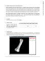
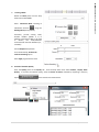
Loading an Image To load an image, select the Image tab, from the drop down menu select Load (default). A new window will be appear, select the image file of interest. 3.
Loading a Surface To load a surface, select the Surface tab, from the drop down menu select Load (default). A new window will be launched enabling you to open the file of interest. For the time being, hide the image by unchecking the checkbox associated with the image in the Object Manager. 16 | T u t o r i a l
IA-FEMesh Tutorial: Proximal Phalanx Bone
4.
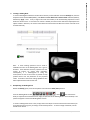
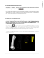
Creating a Building Block To create a Building Block based on the bounds of the bony surface definition select the Block(s) tab, from the drop down menu select Create (default), and check the Create block from surface bounds check box (default), followed by Apply. Note: if only a single surface has been loaded, it will automatically populate the menu within the Surface frame. If more than one surface is loaded, the active surface will be that displayed via the objects window. Moreover, the menu housed within the Surface frame enables the surface of interest to be activated manually. Note: A mesh seeding operation will be used to subdivide each face of the building block into a grid of elements. These elements are then projected onto the surface of interest via closest point projection. Consequently, it is advantageous to bring the vertices/faces as close to the surface as possible to help provide control over the placement of the projected nodes. A number of interactive editing capabilities have been implemented to facilitate this task. 5.
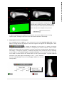
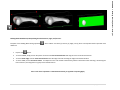
Manipulating the Building Block: Within the Block(s) panel, from the drop down menu select the Build / Edit operation. , select . This activates the From the building blocks toolbar
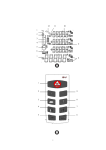
ability to reposition the individual vertices, edges, and/or faces of the building blocks. Once activated, a red sphere will appear at each of the Building Block vertices. To move a building block vertex or face, simply click on the object of interest with the left mouse button (an active element will turn green), and drag it to the desired position. To move an edge of the block, use the middle mouse button. 17 | T u t o r i a l
IA-FEMesh Tutorial: Proximal Phalanx Bone
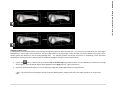
a
c
b
Examples of the Building Block editing operation,
, which enables the block (a) vertices, (b) edges, and (c) faces to be repositioned for improved mesh definitions. Note: The radii of the red spheres may be scaled: To Save the Building Block, select Save from the drop down menu (Note: Cancel will exit the editing operations panel, enabling the drop down menu to be activated and Save to be selected). 6.
Assigning Mesh Seeds to the Building Block. Enter the Mesh panel via the Mesh tab. From the drop down menu select Assign/Edit Mesh Seeds. Note, by default an average element edge length of 1 has been assigned to the edges of each building block. Select to visualize the distribution of mesh seeds (i.e., Number of Divisions) throughout the structure (Note: as the blocks are manipulated, the number of divisions remains constant based on the initial element size calculations, to restore the structure’s average element edge length to 1, select Apply). To change this assignment, an additional drop down menu provides the option of subdividing the block edges via the (1) Element Length or (2) Number of Elements. Once a selection has been made, click on the block of interest with the left mouse button. (an axis system will appear to provide additional verification of the block edges corresponding to the x, y, and z directions). Thereafter, enter the values of choice and select Apply. Cancel to exit the mesh seeds operation. 18 | T u t o r i a l
IA-FEMesh Tutorial: Proximal Phalanx Bone
IA-FEMesh Tutorial: Proximal Phalanx Bone
7.
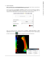
Creating a Mesh Within the Mesh panel, from the drop down menu select Create. Select Volumetric Mesh consisting of hexahedral elements using the Building Block option (Default). Thereafter, provide starting node/ element numbers (default is 1) in addition to descriptive labels to be used to identify the nodes/elements associated with the mesh definition (i.e., set labels). Assume Elliptical Interpolation As an initial attempt, Uncheck the Perform smoothing option. Select Apply to generate the mesh. 8.
A Check of the Mesh Quality Enter the Quality panel via the Quality tab. From the drop down menu select Evaluate / Display Mesh Quality. To visualize the element quality, select the Metric of Choice, followed by requesting a summary report of the mesh for the chosen metric. 19 | T u t o r i a l
9.
Improve mesh quality Within the Quality panel, select Mesh Improvement from the drop down menu. Check to ensure that the Surface, Block and Mesh of interest populate the Mesh Component frame. Select an interpolation method (Elliptical or Transfinite) to establish the interior nodal definitions. Enter the desired number of smoothing iterations (Laplacian smoothing) for the external nodes, and Apply. Note: Be careful to not over smooth the mesh. Too many iterations may yield a mesh of poor quality. Adjust the smoothing parameters, toggling between the Evaluate / Display Mesh Quality and Mesh Improvement operations until the desired mesh for the assigned mesh seeding is achieved. While displaying the metric of interest, depress to invoke a cutting plane to view the internal elements. 20 | T u t o r i a l
IA-FEMesh Tutorial: Proximal Phalanx Bone
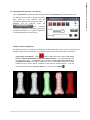
10. Assigning Material Properties – User Defined Select the Materials tab. Within the Materials panel, select the User‐Defined option from the main menu. The element set label used to identify the phalanx bone during the mesh definition step will automatically populate the Element Set menu. If additional sets are preferred, select the button. A number of actions are available for selecting the elements to include/exclude in/from a set (refer to Appendix II for a detailed description of each action). Example: Element Set Definitions The following outlines the procedure for defining two independent element sets: (1) the external layer of elements and (2) the internal elements, representative of the cortical and cancellous bone, respectively. Cortical_Bone Set definition: Select , hold the Ctrl button while using the left mouse button to drag a rubberband box around the elements of interest. The selected elements will be highlighted in green. To accept the chosen elements, click the right mouse button while hovering over the mesh; the accepted elements will turn red. Changing the opacity via the slider enables the user to better visualize, in addition to work with the selected elements. Once the . selection has been finalized, enter a Set Label (e.g., cortical_bone) and Apply 21 | T u t o r i a l
IA-FEMesh Tutorial: Proximal Phalanx Bone
IA-FEMesh Tutorial: Proximal Phalanx Bone
Cancellous_Bone Set definition: Repeat the aforementioned steps for defining the cortical bone with the exception of depressing the button prior to accepting the element selection and assigning a new Set Label (e.g., cancellous_bone). Note: once the selection has been finalized, will close you must reduce the opacity to visualize the elements assigned to the set. Cancel the Define Element Set(s) window. Material Property Assignments Once the desired element sets have been defined, use the drop down menu ‘Element Set’ to select an element set and Enter the Modulus and Poisson’s Ratio in the respective text boxes, and Apply. Repeat this procedure for each material assignment. Once complete, Cancel to exit the operation. Visualizing the Material Property Assignments Within the Materials Panel, from the drop down menu select Display Material Properties. The Element Set to be displayed defaults to all elements. If a particular set is of interest, use the drop down menu to make such a selection. Use definitions. to display a cutting plane which may be manipulated to view the internal element 22 | T u t o r i a l
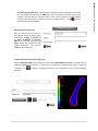
11. Assigning Material Properties – Image‐Based At this point, you may opt to overwrite the user‐defined properties with image‐based materials, or proceed to step 12. Within the Materials panel, select the Image‐Based option from the main menu. Expand the collapsed frame titled Mesh & Image Assignments to ensure that the appropriate Mesh and Image definitions populate the respective menus. Since we previously assigned material properties to two independent element sets, we must overwrite each of them (simply applying the image‐based properties to the mesh as a whole in this scenario will not overwrite the previous user‐defined definitions, and hence the elements would have conflicting material assignments). For each element set defined previously (e.g. cortical_bone, cancellous_bone) do the following: Select the element set of interest, assign a Poisson’s Ratio, select to launch a window, enabling the constants for the modulus calculation to be adjusted. Moreover, select a method of calculating the density; via the Average, Median, or Maximum density value for a given element. Select Apply in the Image‐Based Elastic Modulus window to confirm the calculation constants, etc. Select Apply in the Materials Panel to commit the image‐based properties to the mesh. Repeat this procedure for all element sets for which you would like to assign image‐based material properties. Note: had the user‐defined properties not been assigned, the image‐based properties could have been assigned directly to the set containing all of the elements. 23 | T u t o r i a l
IA-FEMesh Tutorial: Proximal Phalanx Bone
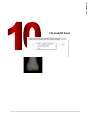
12. Assigning Load and Boundary Conditions Select the Load/BC tab and the STEP ‐ Load/BC Assignments option from the drop down menu. Similar to the element set definitions defined previously, nodes are assigned to sets for designating the load and boundary conditions. Select . From the Node Set toolbar select (this enables the nodes associated with a face of a building block to be readily chosen). Hold the Ctrl button while using the left mouse button to choose a node associated with the building block face of interest. The nodes associated with the selected face will be highlighted in green. To accept the chosen nodes, click the right mouse button while hovering over the mesh; all nodes associated with the chosen face will turn red. Changing the opacity via the slider enables the user to better visualize, in addition to work with the selected nodes. Once the . Cancel will close the selection has been finalized, enter a Set Label (e.g., bounds) and Accept Define Node Set(s) window. In the Step Subheading textbox, provide a descriptive heading for the current step. From the drop down menus select the Load/Displacement type (Force, Displacement, Moment, Rotation), as well as the appropriate Node Set, and Assign the conditions to the x, y, and z directions, respectively. Select Apply to update the Load / BC assignments. Visual confirmation will be provided on the mesh in the View Panel. 24 | T u t o r i a l
IA-FEMesh Tutorial: Proximal Phalanx Bone
IA-FEMesh Tutorial: Proximal Phalanx Bone
Repeat the aforementioned procedure . . . create an additional node set for loading the model and apply a Force. 13. Assigning *STEP Definitions Select the *STEP Definitions button to launch a window housing a number of ABAQUS STEP options such as output and print requests. Please refer to the ABAQUS manual for details regarding these parameters. All parameter requests entered into the textboxes should be delimited by commas. The following represent the default parameters included for the *STEP and Node PRINT and OUTPUT requests (a similar frame exits for Element requests). Use the NSET/ELSET drop down menus to select the set(s) of interest. The selections within a given frame are committed once Apply is selected (Note: the text in the Node/Element frames will become grey once committed. To change the parameters, simply reselect the node/element set from the drop down menu). 25 | T u t o r i a l
14. To Save the FE mesh. The mesh may be saved from any of the mesh related panels (i.e., Mesh, Quality, Materials, and Load/BC Panels) by selecting Save from the respective Main Menu. This enables the user to readily save the mesh throughout the development process. The file will be saved in VTK file format. Recall that the objects populating the Object Manager are automatically saved to the working directory every 5 minutes, unless specified otherwise (refer to §2.2.1 Application Settings). 15. To Export the mesh in ABAQUS file format (*.inp). The mesh may be exported from any of the mesh related panels (i.e., Mesh, Quality, Materials, and Load/BC Panels) by selecting Export ABAQUS file from the respective Main Menu (refer to §2.6.2 Exporting a File in ABAQUS Format (.inp)). 26 | T u t o r i a l
IA-FEMesh Tutorial: Proximal Phalanx Bone
IA-FEMesh Tutorial: Proximal Phalanx Bone
NOTES 27 | T u t o r i a l
IA-FEMesh Tutorial: Proximal Phalanx Bone
NOTES 28 | T u t o r i a l
The Image Panel
4 The Image Panel The Image Panel 29 | T h e
Panels
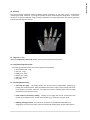
4.1 Overview The current imaging capabilities within IA‐FEMesh provide visualization of the image and of a surface/mesh overlaying the image. Moreover, a CT image set provides for direct material property assignments. In the future, we plan to incorporate additional image processing capabilities for image segmentation and surface generation from the resulting regions of interest. 4.2 Image Tab Æ Load Within the Image Panel, select Load (default) from the panel’s main drop down menu. 4.2.1 Supported Image File Formats The following image file formats are currently supported by IA‐FEMesh • Mayo Analyze (.hdr, .img) • NifTi (.nii, .nii.gz) • NRRD (.nrrd, .nhdr) • META (.mha, .mhd) • GIPL (.gipl, .gipl.gz) • VTK (.vtk) 4.3 Interacting with the Image • Traversing the image The image dataset may be traversed by independently translating or rotating the coordinate planes. With the middle mouse button, select a plane and drag the mouse in the direction of interest. Moreover, if an edge of the plane is selected (again with the middle mouse button), the plane will rotate. • Voxel location and intensity readings Clicking on the image with the left mouse button will provide the coordinate location and the intensity value ((x,y,z):intensity) for a given voxel. • Adjusting the image contrast The contrast of each plane may be adjusted independently by dragging the mouse over the image / plane of interest while holding down the right mouse button. 30 | T h e
Panels
The Image Panel
• Shortcut keys: Shift, accompanied by s or w, toggles between displaying (s) and hiding (w) the image. 4.4 Image Tab Æ Delete Within the Image Tab, select Delete from the drop down menu button, select the image to be removed. 31 | T h e
Panels
The Image Panel
The Surface Panel
5 The Surface Panel The Surface Panel 32 | T h e
Panels
5.1 Overview The modeling techniques for anatomic models may initiate with a triangulated isosurface (STL or VTK format) of the structure(s) of interest, generated directly from a segmented image data set (i.e., CT or MR). Note: the meshing techniques are applicable to geometries other than anatomic structures (refer to the Appendices for examples), so long as they can be loaded as STL or VTK file formats. 5.2 Load/Save/Delete a Surface The Surface Panel main menu affords the user the ability to Load, Save, and Delete a surface. 33 | T h e
Panels
The Surface Panel
The Block(s) Panel
6 The Block(s) Panel The Block(s) Panel 34 | T h e
Panels
6.1 Overview IA‐FEMesh manages the buildings blocks via interactive building/editing techniques. For simple geometries, a single block may suffice (e.g., a phalanx bone of the hand). In such cases, the building block may be automatically defined at the request of the operator, the dimensions of which are established directly from the bounds of the surface of interest. The user also has the option of manually creating a building block. Regardless of the method, once a block is created, subsequent interactive manipulations may be performed on the building block to provide control over the resultant nodal projections. 6.2 Block(s) Tab Æ Create 6.2.1 Create block from surface bounds, followed by Apply, will automatically generate a building block based on the bounds of the surface of interest (note: the edges of the block will align with the axes of global coordinate system). 6.2.2 Create block manually The building block will be extruded perpendicular to the drawing plane; consequently, the surface should be positioned accordingly. Enter an Extrusion Length. Hold down Ctrl and with the left mouse button depressed, drag the mouse to draw the block face to be extruded. A block will automatically be drawn based on the provided extrusion length. The block is committed once Apply (or the right mouse button†) has been depressed. Until then, the user may redefine a block (1) by repeating the aforementioned procedure or (2) by entering a new extrusion length followed by return. If the right mouse button is substituted for Apply, the cursor must be over the block when depressed. †
35 | T h e
Panels
The Block(s) Panel
As anatomic complexity increases, it imposes an increase in the required number of building blocks and hence, attention to their spatial orientation; this in turn requires a means to readily manipulate the building block definitions. In order to make the multiblock technique user friendly, a number of interactive editing operations have been developed and incorporated into IA‐FEMesh. The editing operations implemented to date include: (1) positioning individual vertices/edges/faces of a building block; (2) the subdivision of a building block, or series of building blocks; (3) the addition/deletion of a building block; (4) consolidating two independent block structures; and (5) mirroring and merging a building block structure. The Building Block Operations toolbar is housed in the Block(s) panel under the Build/Edit main menu. 6.3 Block(s) Tab Æ Build/Edit The pages to follow detail each building block operation. These details, along with examples of each operation, are also provided in the Appendices; please refer to the Building Block Operations Toolbar . 36 | T h e
Panels
The Block(s) Panel
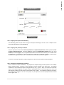
6.3.1 Building Block Operations Toolbar The Building Block Operations Toolbar provides a number of options for creating/manipulating a block structure. Move operations: Allows the constituents of a block (vertices, edges, and faces) to be repositioned independently. To activate an individual component, with the left mouse button click on the part of interest (active elements will be highlighted in green). Note that edge selection requires the use of the middle, as opposed to the left, mouse button. Drag the component to the desired location (be sure to rotate the view to ensure the block is positioned correctly relative to the surface). To move multiple faces simultaneously, hold the shift button while selecting / deselecting the faces of interest. Subdivide operation: Divides the building block of interest in half. With the left mouse button, select the edge along which the block should be divided (edge will be highlighted in green) followed by Apply†. The subdivision will propagate to adjacent blocks throughout the structure automatically. Add operation: Adds a new building block, or blocks, to the face(s) of an existing block/structure. With the left mouse button select the face of interest. To highlight multiple faces, hold the shift button while selecting / deselecting the faces of interest. Again, the active faces will be highlighted in green. Provide an extrusion length, followed by Apply†.1 Note: the coincident vertices generated via the add operation will equivalenced/merged automatically. Delete operation: Removes unwanted blocks from a building block structure. With the left mouse button select the blocks to be removed. To remove multiple blocks simultaneously, hold the shift button while selecting / deselecting the blocks of interest. The active blocks will be highlighted in green. When the selection is complete, select Apply†. Consolidate: Consolidates two or more independently defined building block structures into a single structural definition. To ensure that the blocks are contiguous, the vertices to be shared must be equivalenced. Note: two spheres within the user‐specified tolerance will be highlighted yellow. Mirror: Mirrors a building block, or block structure, about a plane. Select the plane of interest (XY, XZ, or YZ), and position it as desired relative to the original building block definition(s). Equivalence / Merge: Merges the vertices of selected building blocks (within the specified tolerance). Required when building blocks have been mirrored, or when multiple blocks have been independently added adjacent to one another. Note: two spheres within the user‐specified merge tolerance will be highlighted yellow. The right mouse button may replace the ‘Apply’ button for the split, add, and delete operations. In order for this shortcut to be used, the cursor must remain on (or near) the active element (edge, face, or block highlighted in green) of interest when the right mouse button is depressed. †
37 | T h e
Panels
The Block(s) Panel
6.3.2 Rolling Back / Forward a Building Block Structure Each of the ‘move’ operations are committed interactively, the remaining operations require the Apply (or right mouse) button to take effect. Furthermore, with the exception of move, each operation may be rolled back/forward using the undo/redo buttons. If, for example, a block is added to a structure and subsequently manipulated via a sequence of move operations and the undo action is invoked, the building block structure will return to the state prior to having added the block. The redo button will reinstate the manipulated block structure. 6.3.3 Working with a Building Block Sub‐Structure The Sub‐Structure button toggles between viewing/working with a selected portion (sub‐ structure) and the complete block structure. In order to activate the Sub‐Structure button, disable all of the editing operations (i.e., ensure that all editing operation buttons have been deselected). To select a single block or series of blocks, select the Sub‐Structure button and use the left mouse button to select the block of interest, or with the left mouse button drag a box around the blocks of interest. Note, when the move operation is invoked on a substructure, the block faces shared with the remaining structure will be highlighted in yellow. This acts a reminder that should the face and/or associated vertices be moved, they will change the geometry of the neighboring block(s). Furthermore, if the user attempts to add a block to one of these shared faces, the face will turn red, indicating that this is not permissible. To reinstate the building block structure in its entirety, again deselect all editing operations, and select the Complete Structure button. 38 | T h e
Panels
The Block(s) Panel
6.4 Block(s) Tab Æ Delete IA‐FEMesh tracks building block development throughout the building/editing processes. As mentioned previously (‘Rolling Back / Forward a Building Block Structure’), with the exception of ’move’, each of the operations is committed via the Apply command. As a result, Building Blocks are stored sequentially as they are constructed, thereby lending to the ability to roll back/forward. Consequently, when a Building Block is deleted, the user is afforded the opportunity to delete the Current block, or All of the blocks contributing to its development. 39 | T h e
Panels
The Block(s) Panel
The Mesh Panel
7 The Mesh Panel The Mesh Panel 40 | T h e
Panels
The Mesh Panel
7.1 Overview Once the building block structure has been established, the blocks are further subdivided via mesh seeds (arranged in rows, columns, and layers). The mesh seeds of the building block are then projected (via closest point projection) onto the surface of interest. As a result, the mesh seeds are morphed to the bony surface as nodes, to lay the foundation for the FE mesh. Thereafter, Laplacian smoothing may be performed on the surface nodes, followed by interpolation techniques (transfinite/ elliptical) to establish the internal grid of nodes. Once the nodal definitions are established throughout, the volume is filled with hexahedral elements. 7.2 Mesh Tab Æ Assign/Edit Mesh Seeds Once a building block, or series of blocks, has been established, the mesh density must be assigned throughout the model. At the level of an individual block, this is accomplished by simply specifying the number of divisions (i.e., elements) or the desired average element length along each coordinate axis of the block (Rx, Gy, Bz). 7.2.1 Global Mesh Seed Assignment By default, mesh divisions (seeding) of unit length 1† are assumed throughout a building block structure (Note that these divisions are assigned based on the initial block size/shape, consequently the number of divisions will be set and therefore the element size may be altered as the block(s) are manipulated). This element length may be readily redefined by entering the Assign/Edit Mesh Seeds Menu and selecting Apply. Select Color Code Mesh Seeds to see the number of divisions assigned to each edge. The user has the option of reassigning new mesh seeds based on (1) Element Length or (2) the Number of Divisions along a block edge. The seeds may be assigned globally to the structure by entering the desired length or number of divisions along the Rx, Gy, and Bz directions (globally, these directions correspond to the x, y, and z axes respectively). †
Refer to §2.2.1 Application Settings for details regarding changing the default value for the mesh seed length. 41 | T h e
Panels
The Mesh Panel
7.2.2 Local Mesh Seed Assignment The mesh seeding may also be assigned locally. This is accomplished by selecting the block of interest and assigning the mesh seeds based on (1) Element length or (2) the Number of Divisions along the block edge. A Building Block selected for mesh seed assignment will be highlighted by the presence of a local axis system (Rx, Gy, Bz). 42 | T h e
Panels
The Mesh Panel
Seeds may be assigned in such a way that they affect only the block under consideration. For example, in the example below, the mesh seeds on the Gy axis were increased from 8 to 16. As a result, the four edges of the block parallel to the Gy axis were assigned 16 subdivisions (illustrated in blue). In this example, the edges of the block parallel to the Rx and Bz axes share edges with adjacent blocks. Consequently, the subdivision information (mesh seeding) is transferred across blocks at the shared edges. For example, in the example below, the mesh seeds on the Rx axis were increased from 10 to 20. As a result, each of the edges through the structure parallel to the Rx axis were assigned 20 subdivisions (illustrated in blue). 43 | T h e
Panels
The Mesh Panel
7.3 Mesh Tab Æ Create Select a Mesh/Element type: Volumetric Mesh (Hex; default) or Surface Mesh (Quad, Tri); note that tetrahedral meshing is currently disabled. 7.3.1 Volumetric Mesh For a Volumetric Mesh the dropdown menu provides two mesh generation options (1) Building Block Projection (default) and (2) Extrude, which extrudes a select set of element faces a uniform, user specified, distance. Each method generates 8‐noded hexahedral elements (ABAQUS element type = C3D8). Building Block Projection The grid of nodes established via the building block mesh seed assignments are projected onto the surface of interest using closest point projection. Thereafter, the user has the option of using transfinite or elliptical interpolation to establish the interior nodes. If need be, the user has the option of smoothing the mesh via Laplacian Smoothing (refer to §7.4 Mesh Improvement). Extrude A select set of elements may be extruded along their normals a specified distance (Extrusion Length) and Number of Divisions. When the Extrude Elements button is invoked, a window will open which houses the aforementioned parameters, accompanied by the Element 44 | T h e
Panels
Selection Toolbar (refer to Appendix II). It is recommended that material property assignments are made to the underlying, or base, mesh prior to extruding a mesh, as this will ease the element selection process. 7.3.2 Surface Mesh For a Surface Mesh the dropdown menu provides two mesh generation options (1) Building Block Projection (default) and (2) Extract which extracts the element faces from a volumetric mesh for a select set of elements. For example, this may be used to define a rigid body on the backside of a volumetric mesh. Both quadrilateral and triangular elements are supported. The surface mesh definitions currently assume rigid definitions (i.e., ABAQUS element TYPE=R3D4 and R3D3). A reference node (filename_RN) will automatically be assigned to the rigid mesh with coordinates approximating the geometric center of the mesh. Note: this reference node will automatically populate the Node Set menu within the Load/BC panel. Building Block Projection The grid of nodes established via the building block mesh seed assignments are projected onto the surface of interest using closest point projection. If need be, the user has the option of smoothing the mesh (refer to §7.4 Mesh Improvement). Extract A select set of elements may be extracted from a volumetric mesh as a surface mesh. When the Extract Elements button is invoked, a window will open housing the Element Selection Toolbar (refer to Appendix II). It is recommended that material properties are assigned to the underlying, or base, mesh prior to extracting a mesh, as this will ease the element selection process. When a mesh is extracted, two mesh definitions will populate the Object Manager (e.g., index_proximal_Extract‐1 and index_proximal_Mesh_Extract‐1). The former will consist solely of the quadrilateral surface elements, while the latter is a mixed mesh, consisting of both the hexahedral and quadrilateral elements. 7.3.3 Node/Element Numbering and Labels By default the node/element numbers start counting consecutively from 1 unless specified otherwise. The user is also prompted to provide a label for the respective nodes/elements sets. As elements are added, the number picks up where the previous set ended. The user has the option of overriding this value. Moreover, the user has the option of renumbering a set of nodes/elements via the Renumber Nodes/Elements action under the main Mesh drop down menu. 7.4 Mesh Improvement Due to variations in the curvature of the underlying surface, the distribution of the projected nodes may be suboptimal. As a result, Laplacian smoothing has been incorporated into IA‐FEMesh as an option for smoothing the projected surface mesh. Laplacian smoothing acts to equalize the elemental edge lengths by adjusting the location of each node to the geometric center of its neighboring nodes. During this process, there is a tendency for the node being repositioned to move away from the surface. To ensure that the surface of the finite element mesh remains true to the desired underlying image‐based surface representation, the repositioned node is again projected onto the underlying surface using closest‐point projection. Once the surface nodes are established, elliptical or transfinite interpolation may be used to compute the interior nodes; thereafter, the volume is filled with hexahedral elements. 45 | T h e
Panels
The Mesh Panel
The Mesh Panel
7.4.1 Laplacian Smoothing By default smoothing is evoked for the meshes created directly from a Building Block structure. Deselect the Perform Smoothing check box to deactivate the smoothing. The Smoothing Parameters frame houses the parameters used to control the number of Laplacian smoothing iterations to be performed (default = 1). If additional smoothing is required once the mesh is generated, these capabilities are provided in the Quality Panel, under the Mesh Improvement menu. 7.4.2 Interior Node Interpolation Methods The user has the option of choosing between Transfinite or Elliptical Interpolation Methods for internal node calculations. Transfinite Interpolation The interior points of the mesh are generated using transfinite interpolation. This method defines an algebraic coordinate transformation from the rectilinear grid(s) defined by the building block(s) onto the physical domain bounded by the surface (Note: the current number of default iterations has been set to 10). Elliptical Interpolation During Elliptic grid generation, the initial grid (algebraically computed using transfinite interpolation) is relaxed iteratively using a series of elliptic partial differential equations, known as Poisson grid generation equations.. 7.5 Mesh Tab Æ Renumber Nodes/Elements From the drop down menu select the Node/Element Set label to be renumbered and in the textbox enter the corresponding Starting Node/Element Number. 46 | T h e
Panels
The Quality Panel
8 The Quality Panel The Quality Panel 47 | T h e
Panels
The Quality Panel
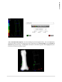
8.1 Overview Regardless of the meshing technique, the solution of a finite element analysis is highly dependent on the quality of the mesh. In addition to the mesh generation routines, algorithms have been included for evaluating and improving the ensuing mesh. These operations are housed in the Quality Panel. The mesh quality application utilizes the open‐source VERDICT library to analyze element quality according to several metrics: Volume, Edge Collapse, Jacobian, Skew, and Angle out of Bounds. These quality values are assigned per element and visualized using the VTK library. Since datasets generally contain a large number of elements, interactive tools have been developed that allow user to dynamically position a “cutting plane” within the dataset to expose internal elements. Furthermore, the elements may be scaled (via an element scaling option) for improved visualization. The overall objective is to make the mesh generation process more efficient by providing rapid, visual feedback to the user. 48 | T h e
Panels
The Quality Panel
8.2 Quality Tab Æ Evaluate / Display Mesh Quality The following details the options available for evaluating and displaying the resulting mesh quality. 8.2.1 Quality Metrics: Volume: the volume of a hexahedron is the product of the magnitude of the three principal axes. An element is considered to be valid if its volume is greater than Zero. Edge Collapse: A hexahedral element has twelve edges. It is considered a degenerate/collapsed element if the number of edges is less than twelve. For viewing purposes, the normal and degenerate elements are assigned values of 1 and ‐1, respectively. Jacobian: the Jacobian is a measure of deviation of an element from an ideally shaped element. A negative Jacobian is indicative of severe element distortion. Skew: Detects element distortions which arise due to large or small angles. Calculates the skew angle for each face of a hexahedral element and reports the maximum. Skew ranges from [0, 1], where 0 represents a degenerate element. Angle Out of Bounds: Calculates the angular deviation between adjacent faces of the hexahedral element. An element is considered distorted if an angle measures less than 450 or greater than 1350. 49 | T h e
Panels
The Quality Panel
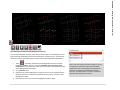
8.2.2 A Mesh Quality Summary Report The Summary Report provides an overview of the mesh for a given metric. For example, the illustrated summary suggests that a mesh consisting of 3978 elements yielded no distorted elements in terms of volume, while the minimum and maximum volumes were 0.014 and 2.536, respectively. Moreover, the average element volume measured 0.344 with a variance of 0.092. Had there been a given number of distorted elements, they would have been listed by Element ID and metric quality value in the window provided. The distorted element summary may be written to a file by selecting Save. 50 | T h e
Panels
The Quality Panel
8.2.3 Quality Display Options Toggles display of the legend Cross‐sectional view that may be manipulated by translating and rotating the cutting plane. The Invert View checkbox toggles between the viewing direction with respect to the normal of the cutting plane. Display Options provide control over the display of metric. For example, the spectrum of the legend may be assigned from red‐to‐blue (default), ranging from the minimum to the maximum metric value, respectively. It may also be changed to traverse blue‐to‐
red. The limits of the scale may also be adjusted. By default, the maximum and minimum metric values are assigned. These values may be adjusted, by checking the Specify checkbox and assigning the Minimum and Maximum values of interest. Note that the elements exceeding the assigned maximum value will be color‐coded white, while those less than the minimum assume the color black. The number of significant figures displayed on the legend and the legend title may also be changed. 51 | T h e
Panels
The Quality Panel
8.3 Quality Tab ÆMesh Improvement The mesh Improvement options detailed in §7.4 Mesh Improvement are reiterated in the Quality panel. This enables the mesh quality to be evaluated and then improved without returning to the Mesh Panel. The user has the option between Elliptical and Transfinite Interpolation methods, in addition to the number of Laplacian smoothing iterations to perform. 52 | T h e
Panels
The Materials Panel
9 The Materials Panel The Materials Panel 53 | T h e
Panels
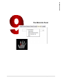
9.1 Overview The Materials Panel affords the user the option of assigning user‐defined, or image‐based, material properties. Moreover, the user has the option of displaying the resulting material definitions, as well as saving and/or exporting the mesh. 9.2 Materials Tab Æ User‐Defined User‐Defined Material Property Assignments To assign User‐Defined Material Properties to a set (or sets) of elements, the elements must be grouped accordingly. To define individual element sets, select the Element Set Definitions button to launch a window housing the element selection toolbar (described in detail on the pages that follow). Once the sets are defined they will populate the drop down menu titled ‘Element Set’. From this menu select the set of interest and assign the Modulus and Poisson’s ratio, followed by Apply. Repeat the material assignments as needed. Note that the Modulus and Poisson’s ratio text boxes will retain the assigned values for a given set for future reference. Moreover, to remove a material assignment, simply clear the textbox and Apply. 9.2.1 Establishing Element Set Definitions To assign material properties to, or request output data from, a set (or sets) of elements, the elements must be grouped accordingly. To define individual element sets, select the Element Set Definitions button to launch a window housing the Element Selection Toolbar (described in detail on the pages that follow). Once the sets are defined they will populate the drop down menu titled ‘Element Set’. 54 | T h e
Panels
The Materials Panel
The Materials Panel
The Element Selection Toolbar provides a number of options for selecting/grouping elements. While making an element selection with any of these tools, hold down the Ctrl button and select the elements with the left mouse button. The element selection will be highlighted in green and confirmed with a click of the right mouse button (thereafter the elements turn red). Elements may continue to be added/removed from the set until a label is assigned and Applied. The following highlights each application. Examples of each are included on the next page. All Elements: all elements throughout the volumetric mesh within the outlined field. Surface Elements: all surface elements within the outlined field. Visible Surface Elements: visible surface elements within the outlined field. Elements Associated with a Block Face: all elements associated with a given block face. Single Element: a single element. Inclusion / Exclusion: toggles between including (+) and excluding (‐) the selected entities from a given set. The Opacity slider enables the user to readily view and work with the element selections. The opacity level acts to restrict the elements active for selection. For example, when the mesh is fully opaque (1.00 (100%)), all elements are active and may be selected for inclusion or exclusion. Once the opacity has been reduced, only the highlighted elements (selected previously) remain active. This enables the user to refine a series of elements defining a given set. The aforementioned selection methods will perform similarly on the subset of elements, with the exception of the face selection option (which becomes inactive). If need be, Clears the element selection prior to being assigned an element set label. Assign a Set Label to the selected elements, followed by . 55 | T h e
Panels
The Materials Panel
9.2.2 Element Set Selection Toolbar Capabilities Examples of Inclusion (+) Examples of Exclusion (‐) The remaining selection capabilities also function under the exclusion option, unfortunately the printed images are difficult to visualize. The exclusion option was included, for the most part, as a means to readily refine an element set selection. An example is provided in Appendix II, Combining the Inclusion(+) and Exclusion (‐) capabilities to edit an element set. 56 | T h e
Panels
The Materials Panel
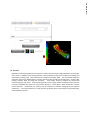
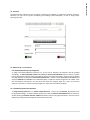
9.3 Materials Tab Æ Image‐Based Image‐Based Material Property Assignments Once a mesh has been generated there is a direct correspondence between the model and the imaging data used to generate the bony surface definition. In addition to assigning user specified material assignments (E, ν), IA‐FEMesh allows the user to assign element‐wise material properties unique to each bone/specimen based on the CT number. The density information provided by the dataset is preserved by considering all of the CT voxels that fall within the element. The user has the option of averaging the densities of each voxel contributing to an element, calculating the median density value, or assigning the maximum density contributing to the element. Thereafter, the elastic moduli are calculated on an element‐by‐element basis, thereby establishing the local stiffness. Subject specificity based on material definitions is facilitated by the fact that a linear relationship exists between digital CT scan data and the apparent density of bone. Moreover, various models can be found in the literature for the relationship between bone density and elastic modulus. For the sake of generality, the elastic modulus c
, where E is the elastic modulus, ρapp the apparent has been defined according to the equation E = a + bρ app
density, and a, b, and c the model parameters. These parameters are treated as variables, they may be tuned by the user according to the requirements of the specific problem (default values: a = 0, b=2875, and c = 3). 57 | T h e
Panels
The Materials Panel
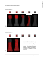
The Mesh & Image Assignments collapsed frame houses the Mesh and the Image from which the materials will be assigned. If multiple objects are open, ensure the appropriate object identifiers are selected. If an element set to which the materials are to be assigned has yet to be defined, select the Element Set Definitions button (refer to Appendix II for a description of the tools available for assigning elements to a set). Otherwise, select the desired element set from the Element Set menu, and assign the corresponding Poisson’s Ratio in the text box. 9.3.1 Binning Material Property Assignments Rather than assign unique material definitions on an elemental basis, it may be beneficial to assign a single elastic modulus to a set of elements. For example, material 1 may consist of elements with a modulus value in the range E1 ≤ E ≤ Emax, while the range for material 2 takes the form E2 ≤ E < E1, and so on. This capability alleviates any potential restrictions imposed by some finite element modeling packages with regard to a limited number of material definitions. The Number of Bins as well as the range (check Specify Range) over which the moduli span (min and max) may be assigned. 58 | T h e
Panels
The Materials Panel
9.4 Materials Tab Æ Display Material Properties The Display Material Properties panel provides a means to visualize the distribution of the assigned moduli values throughout the mesh. The functionalities are similar to those provided for viewing the quality metrics. Toggles display of the legend Cross‐sectional view that may be manipulated by translating and rotating the cutting plane. The Invert View checkbox toggles between the viewing direction with respect to the normal of the cutting plane. Display Options provide control over the display of the material properties. For example, the spectrum of the legend may be assigned from red‐to‐blue (default), ranging from the minimum to the maximum metric value, respectively. It may also be changed to traverse blue‐to‐red. The limits of the scale may also be adjusted. By default, the maximum and minimum metric values are assigned. These values may be adjusted, by checking the Specify checkbox and assigning the Minimum and Maximum values of interest. Note that the elements exceeding the assigned maximum value will be color‐coded white, while those less than the minimum assume the color black. The number of significant figures displayed on the legend and the legend title may also be changed. 59 | T h e
Panels
The Load/BC Panel
10 The Load/BC Panel The Load/BC Panel 60 | T h e
Panels
10.1 Overview The Loading / Boundary conditions assigned to a mesh play an integral role in an FE analysis. The Load/BC Panel was designed to enable the user to assign nodes to node sets which may then be assigned load and boundary conditions. Moreover, these Load/BC assignments may be displayed directly on the mesh for visual confirmation. Lastly, the user may request STEP information directly from this panel, namely from the STEP‐Load/BC Assignments menu). The Load/BC panel also provides menus for Exporting the model in ABAQUS File format as well as saving the mesh. 61 | T h e
Panels
The Load/BC Panel
10.2 Load/BC Tab Æ STEP ‐ Load/BC Assignments Interactive tools have been implemented to identify nodes for load and boundary condition assignments. The user is afforded options for both single and multi‐node selection. Multi‐node selection takes several forms. The user has the option of selecting the series of nodes associated with a face of a building block or by selecting a group of nodes via an interactive rubberband box selection tool. The box selection tool may be used to select all of the nodes defining the continuum mesh within the selected volume, or limit the nodes to those on the surface of the mesh. 10.2.1 Establishing Node Set Definitions To assign Load and/or Boundary Conditions to, or request output data from, a set (or sets) of nodes, the nodes must be grouped accordingly. To define individual node sets, select the Node Set Definitions button to launch a window housing the Node Selection Toolbar (described in detail on the pages that follow). Once the sets are defined they will populate the drop down menu titled ‘Node Set’. 62 | T h e
Panels
The Load/BC Panel
The Load/BC Panel
The Node Selection Toolbar provides a number of options for selecting/grouping nodes. While making a nodal selection with any of these tools, hold down the Ctrl button and select the nodes with the left mouse button. The nodal selection will be highlighted in green and confirmed with a click of the right mouse button (thereafter the nodes turn red). Nodes may continue to be added/removed from the set until a label is assigned and Applied. The following highlights each application. Examples of each are included on the next page. All Nodes: all nodes throughout the volumetric mesh within the outlined field. Surface Nodes: all surface nodes within the outlined field. Visible Surface Nodes: visible surface nodes within the outlined field. Nodes associated with a block face: all nodes associated with a given block face by choosing a single node on that face. Single Node: a single node. Inclusion / Exclusion: toggles between including (+) and excluding (‐) the selected entities from a given set. The Opacity slider enables the user to readily view and work with the nodal selections. The opacity level acts to restrict the nodes active for selection. For example, when the mesh is fully opaque (100%), all nodes are active and may be selected for inclusion or exclusion. Once the opacity has been reduced, only the highlighted nodes (selected previously) remain active. This enables the user to view/refine a series of nodes defining a given set. Some of the selection operations become inactive when the opacity < 1.00. If need be, Clears the node selection prior to being assigned a node set label. Assign a Set Label to the selected nodes, followed by . 63 | T h e
Panels
The Load/BC Panel
10.2.2 Node Set Selection Toolbar Capabilities Example node selections chosen via each of the nodal selection tools. 64 | T h e
Panels
The Load/BC Panel
10.2.3 Assigning a Descriptive STEP Subheading The Subheading textbox may be used to assign a descriptive subheading to the STEP. Note: ABAQUS retains only the first 80 characters of the subheading. 10.2.4 Assigning Load / Boundary Conditions From the drop down menu button choose Force/Moment or Displacement/Rotation. Select a predefined node set from the drop down menu. Thereafter, assign the respective Load/Boundary Condition in the x, y, and z textboxes, followed by Apply. Note, an applied load/moment will be distributed uniformly over all nodes within an assigned set. For example, if a node set contains 10 nodes and a 10 N load is applied, the load will be distributed as 1N applied to each node. Furthermore, rotations should be entered in degrees. To remove a load and/or boundary condition assignment, simply clear the respective textbox and Apply. 10.2.5 Displaying the Load/Boundary Conditions Once a node set has been established, it will populate the Load/BC Display window (housed in the Load/BC Display collapsed frame). Moreover, visual confirmation will be provided in the View Panel. The applied conditions are color‐coded with respect to the global axes (x: red, y: green, z: blue). The arrows are scaled with respect to the largest magnitude for a given condition (load/displacement). The overall appearance of the load and boundary conditions may be scaled via the provided ‘scale’ textbox. The checkboxes enable the visibility of the Load/BC to be toggled on and off. The opacity may be adjusted to view forces/displacements directed within a given mesh. 65 | T h e
Panels
The Load/BC Panel
10.2.6 Assigning *STEP Definitions Select the *STEP Definitions button to launch a window housing a number of STEP options such as output and print requests. Please refer to the ABAQUS manuals for details regarding these parameters. As illustrated, default parameters have been provided. To accept the default step assignments, simply select Apply in the STEP frame, choose the desired NSETs and ELSETs from the respective drop down menus and Apply. Note, Apply must be selected for each set assignment. When the output request parameters have been committed, they will be grayed out. To reactivate the frame, select the NSET/ELSET of interest from the drop down menu. To change a parameter, simply uncheck a check box, change a drop down menu, or update the respective textbox, and Apply. All parameter requests entered into the textboxes should be delimited by commas. 10.2.7 Multiple Step Analysis Oftentimes it is beneficial to divide the load history of a simulation into a number of steps. As a result, the user may add/remove steps by selecting the +STEP/‐STEP buttons. As steps are requested, tabbed panels will be added sequentially. Using the methods described above, the load and boundary conditions can then be assigned to the respective steps. Note, as additional steps are added, the STEP definitions of the new step will take on the assignments from the previous step. As a result, you may need to only assign the Load and Boundary conditions for the new step. 66 | T h e
Panels
Appendix I: Building Block Operations ‐ Examples APPENDIX I Building Block Operations 67 | A p p e n d i c e s
APPENDIX I: Building Block Operations - Examples
Building Block Operations Toolbar Move operations: Allows the constituents of a block (vertices, edges, and faces) to be repositioned independently. To activate an individual component, with the left mouse button click on the part of interest (active elements will be highlighted in green). Note that edge selection requires the use of the middle, as opposed to the left, mouse button. Drag the component to the desired location (be sure to rotate the view to ensure the block is positioned correctly relative to the surface). To move multiple faces simultaneously, hold the shift button while selecting / deselecting the faces of interest. Subdivide operation: Divides the building block of interest in half. With the left mouse button, select the edge along which the block should be divided (edge will be highlighted in green) followed by Apply†. The subdivision will propagate to adjacent blocks throughout the structure automatically. Add operation: Adds a new building block, or blocks, to the face(s) of an existing block/structure. With the left mouse button select the face of interest. To highlight multiple faces, hold the shift button while selecting / deselecting the faces of interest. Again, the active faces will be highlighted in green. Provide an extrusion length, followed by Apply†.2 Note: the coincident vertices generated via the add operation will equivalenced/merged automatically. Delete operation: Removes unwanted blocks from a building block structure. With the left mouse button select the blocks to be removed. To remove multiple blocks simultaneously, hold the shift button while selecting / deselecting the blocks of interest. The active blocks will be highlighted in green. When the selection is complete, select Apply†. Consolidate: Consolidates two or more independently defined building block structures into a single structural definition. To ensure that the blocks are contiguous, the vertices to be shared must be equivalenced. Note: two spheres within the user‐specified tolerance will be highlighted yellow. Mirror: Mirrors a building block, or block structure, about a plane. Select the plane of interest (XY, XZ, or YZ), and position it as desired relative to the original building block definition(s). Equivalence / Merge: Merges the vertices of selected building blocks (within the specified tolerance). Required when building blocks have been mirrored, or when multiple blocks have been independently added adjacent to one another. Note: two spheres within the user‐specified merge tolerance will be highlighted yellow. The right mouse button may replace the ‘Apply’ button for the split, add, and delete operations. In order for this shortcut to be used, the cursor must remain on (or near) the active element (edge, face, or block highlighted in green) of interest when the right mouse button is depressed. †
68 | A p p e n d i c e s
APPENDIX I: Building Block Operations - Examples
Building Block Modifications; Manipulating the Block Vertices, Edges, and/or Faces. Examples of the Building Block editing operation,
definitions. , which enables the block (a) vertices, (b) edges, and (c) faces to be repositioned for improved mesh 1.
Depress the button. 2.
To move a vertex, simply click on the sphere of interest with the left mouse button and drag the vertex to the desired location. 3.
To move a block edge, with the center mouse button select the edge of interest and drag the edge to the desired location. 4.
To move a face, use the left mouse button. If multiple faces are to be moved simultaneously, hold the shift button while selecting / deselecting the faces of interest, and drag them as a group to the desired location. Note: Each ‘move’ operation is committed interactively, as opposed to requiring Apply. 69 | A p p e n d i c e s
APPENDIX I: Building Block Operations - Examples APPENDIX I: Building Block Operations - Examples Subdividing a block in two. A building block may be divided in half by simply choosing the edge along which the block should be split. As a means of visual confirmation, the active edge is highlighted by a color change, and then bisected. The three edges parallel to the active edge are also bisected and vertices defined at the division points, thereby yielding two blocks from the pre‐existing building block. The following provides step‐by‐step instructions for subdividing a block and further subdividing the resulting structure to illustrate how the subdivision propagates through a series of adjacent blocks. 1.
Depress the button. With the left mouse button click on the block edge along which the block is to be subdivided (as confirmation, the edge will turn green). Once the desired edge has been highlighted, select Apply (shortcut: right mouse button). 2.
Repeat the aforementioned sequence, this time selecting an edge with parallel edges shared by an adjacent block. * Note: The split function will propagate through to adjacent building blocks, dividing those blocks with edges parallel to the original split edge. 70 | A p p e n d i c e s
Adding to a Building Block … One block at a time. Blocks may be added independently or as a group. The figure above illustrates two blocks being added independently. The following provides step‐by‐step instructions for doing so once a base block has been established: 1.
2.
3.
Select the button. Enter the desired extrusion length and with the left mouse button click on the face to which a new block will be added (as confirmation, the face will turn green; Note: extrusion length assignment and face selection are not order dependent). Once the desired face has been highlighted, select Apply (shortcut: right mouse button). As illustrated, follow the same steps outlined above (step 1) for a second face sharing a corner with the first. When faces are added independently, each block is projected perpendicular to the chosen face. As a result, if the new blocks are to share an edge, the respective vertices must be merged as follows. Select . The vertices to be merged must be repositioned within close proximity to one another. (Note: the individual components of the blocks may be repositioned using the same techniques as the move operations.) Two vertices positioned within the assigned tolerance of one another will be highlighted in yellow. Once all of the vertices to be equivalenced are yellow, select apply. If the action is cancelled, or another editing operation is selected prior to equivalencing the vertices, all position changes will be removed and the block structure will return to the state prior to the manipulations. An example of an equivalenced vertex is highlighted in the figure above by an orange circle. Refer to the next example to add multiple blocks simultaneously, thereby bypassing the need to equivalence. 71 | A p p e n d i c e s
APPENDIX I: Building Block Operations - Examples APPENDIX I: Building Block Operations - Examples Adding to a Building Block … Multiple blocks simultaneously. Multiple blocks may be added to a block/structure simultaneously. The following provides step‐by‐step instructions for doing so once a base block or structure has been established: 1.
2.
Depress the button. Enter the desired extrusion length and with the left mouse button (while holding down the shift key) click on each of the faces to which a new block will be added (as confirmation, the face will turn green; Note: extrusion length assignment and face selection are not order dependent). Once the desired faces have been highlighted, select Apply (shortcut: right mouse button). This application automatically equivalences the vertices shared between adjacent blocks. 72 | A p p e n d i c e s
APPENDIX I: Building Block Operations - Examples Removing a Building Block or Series of Blocks. Blocks may be removed independently or as a group. The figure above illustrates a single block being removed from a structure. The following provides step‐
by‐step instructions for doing so once a base block or structure has been established: 1.
Select the button. With the left mouse button, click on the block to be removed (as confirmation, the block will turn green). If multiple blocks are to be removed simultaneously, hold down the shift key while making multiple block selections. Once the desired block/s has/have been highlighted, select Apply (shortcut: right mouse button). 73 | A p p e n d i c e s
APPENDIX I: Building Block Operations - Examples Consolidating Two Independent Building Block Structures. As the model complexity increases, there may be instances when two building blocks have been generated independently and must be merged into a single structure. The following details the steps for consolidating two structures constructed and loaded independently. 1.
2.
3.
4.
Select . A window, populated by the building block structures currently loaded in IA‐FEMesh, will open. Check the checkbox of the structure(s) to be manipulated. Similar to the move operation, the vertices of the active structure(s) will be highlighted by red spheres. Set a Tolerance value. Reposition the vertices/edges/faces to bring the vertices to be merged within the specified tolerance; once within the specified tolerance, the two vertices will be highlighted in yellow. Once all of the vertices of interest are highlighted in yellow, Apply. Note: Once the vertices have been merged, if you opt to reposition a vertex from within the Consolidate operation be sure to select Apply once repositioned such that the changes are committed to the new structure. The other option is to return to the Move operation and reposition the vertices. 74 | A p p e n d i c e s
APPENDIX I: Building Block Operations - Examples Mirroring a block structure When possible, take advantage of symmetry. A pre‐existing building block, or series of blocks, may be mirrored about a plane positioned relative to the base block structure. A plane, parallel to one of the coordinate planes may be assigned automatically, or it may be interactively repositioned to a desired orientation. Recall, neighboring blocks share vertices. As a result, the vertices of the new structure must be merged with those from which it was mirrored. Consequently, the vertices of interest are moved into close proximity to one another and merged based on a radial tolerance assigned by the user. The following provides step‐by‐step instructions for mirroring a base block or structure: 1.
2.
3.
Depress the button. Select the plane of interest (xy, xz, or yz). Use the left mouse button to position (translate/rotate) the plane with respect to the base structure. Select Apply. The vertices along the mirroring plane must be merged. Consequently, these vertices must be coincident (within tolerance). Activate the Equivalence/Merge operation by selecting . Within this operation, the vertices/edges/faces may be repositioned (similar to move). Enter a radial tolerance. When the vertices of interest are within the specified tolerance they will be highlighted in yellow. Once all of the vertices along the mirror plane are all yellow, select Apply to merge the mirrored structures. 75 | A p p e n d i c e s
Appendix II: Element/Node Set Selection APPENDIX II Element/Node Set Selection 76 | A p p e n d i c e s
APPENDIX II: Element/Node Set Selection Toolbar
The Element Selection Toolbar provides a number of options for selecting/grouping elements. While making an element selection with any of these tools, hold down the Ctrl button and select the elements with the left mouse button. The element selection will be highlighted in green and confirmed with a click of the right mouse button (thereafter the elements turn red). Elements may continue to be added/removed from the set until a label is assigned and Applied. The following highlights each application. All Elements: all elements throughout the volumetric mesh within the outlined field. Surface Elements: all surface elements within the outlined field. Visible Surface Elements: visible surface elements within the outlined field. Elements Associated with a Block Face: all elements associated with a given block face. Single Element: a single element. Inclusion / Exclusion: toggles between including (+) and excluding (‐) the selected entities from a given set. The Opacity slider enables the user to readily view and work with the element selections. The opacity level acts to restrict the elements active for selection. For example, when the mesh is fully opaque (1.00 (100%)), all elements are active and may be selected for inclusion or exclusion. Once the opacity has been reduced, only the highlighted elements (selected previously) remain active. This enables the user to refine a series of elements defining a given set. The aforementioned selection methods will perform similarly on the subset of elements, with the exception of the face selection option (which becomes inactive). If need be, Clears the element selection prior to being assigned an element set label. Assign a Set Label to the selected elements, followed by . 77 | A p p e n d i c e s
APPENDIX II: Element/Node Set Selection Toolbar
APPENDIX II: Element/Node Set Selection Toolbar
The above illustration exemplifies the element selection process. Suppose the ‘all elements tool’ was selected. Holding the left mouse button and the Ctrl key, drag a box around the elements of interest (the selected elements will be highlighted in green). To confirm this selection, with the cursor over the mesh, click the right mouse button (the highlighted elements will change to red). Reducing the opacity will provide an internal view of the selection as well as enable the user to work with the element selection. Combining the Inclusion(+) and Exclusion (‐) capabilities to edit an element set For example, an initial set of elements are selected / included . To refine the selection, the opacity is first decreased, and a subset of the elements are then excluded by toggling the inclusion/exclusion buttons to . The elements to be removed are chosen via the appropriate selection operation (highlighted below in green). With a click of the right mouse button the highlighted elements are removed from the element set. 78 | A p p e n d i c e s
The Node Selection Toolbar provides a number of options for selecting/grouping nodes. While making a nodal selection with any of these tools, hold down the Ctrl button and select the nodes with the left mouse button. The nodal selection will be highlighted in green and confirmed with a click of the right mouse button (thereafter the nodes turn red). Nodes may continue to be added/removed from the set until a label is assigned and Applied. The following highlights each application. All Nodes: all nodes throughout the volumetric mesh within the outlined field. Surface Nodes: all surface nodes within the outlined field. Visible Surface Nodes: visible surface nodes within the outlined field. Nodes associated with a block face: all nodes associated with a given block face by choosing a single node on that face. Single Node: a single node. Inclusion / Exclusion: toggles between including (+) and excluding (‐) the selected entities from a given set. The Opacity slider enables the user to readily view and work with the nodal selections. The opacity level acts to restrict the nodes active for selection. For example, when the mesh is fully opaque (100%), all nodes are active and may be selected for inclusion or exclusion. Once the opacity has been reduced, only the highlighted nodes (selected previously) remain active. This enables the user to view/refine a series of nodes defining a given set. Some of the selection operations become inactive when the opacity < 1.00. If need be, Clears the node selection prior to being assigned a node set label. Assign a Set Label to the selected nodes, followed by . 79 | A p p e n d i c e s
APPENDIX II: Element/Node Set Selection Toolbars
APPENDIX II: Element/Node Set Selection Toolbars
Combining the Inclusion(+) and Exclusion (‐) capabilities to edit an element set Similar to the operations established for selecting elements, For example, an initial set of nodes are selected / included . To refine the selection, the opacity is first . decreased, and a subset of the nodes are then excluded by toggling the inclusion/exclusion buttons to The nodes to be removed are chosen via the appropriate selection operation (highlighted in green). With a click of the right mouse button the highlighted nodes are removed from the set definition. 80 | A p p e n d i c e s
Appendix III: Mesh Examples APPENDIX III Mesh Examples 81 | A p p e n d i c e s
APPENDIX III: Example Mesh Definitions
APPENDIX III: Example Mesh Definitions
Phalanx bones and the Ascension® PIP Total Joint Replacement TM
Carpal Bones and Universal 2 Total Wrist Implant 82 | A p p e n d i c e s
APPENDIX III: Example Mesh Definitions
Human Brain Aneurysm 83 | A p p e n d i c e s
APPENDIX III: Example Mesh Definitions
Mechanical Joint 84 | A p p e n d i c e s
APPENDIX III: Example Mesh Definitions
INDEX A Application Settings ∙ 7 Apply Button ∙ 14 Assign/Edit Mesh Seeds ∙ 41 Global Mesh Seed Assignment ∙ 41 Local Mesh Seed Assignment ∙ 42 Assigning Boundary Conditions ∙ 65 Assigning Loads ∙ 65 Autosave ∙ 7 I Image‐Based Material Properties ∙ 57 Interacting with the Image ∙ 30 L Load Assignments ∙ 62 Loading ∙ See Assigning Loads Loading an Object ∙ 13 B Boundary Conditions ∙ 62, See Assigning Boundary Conditions Building Block Operations Toolbar ∙ 36, 37, 68 C Cancel Button ∙ 14 Collapsible Frames ∙ 13 Command Panel ∙ 9 Creating a Building Block ∙ 35 From surface bounds ∙ 35 Manually ∙ 35 D Defining a Node Set ∙ See Node Set Definitions Defining an Element Set ∙ See Element Set Defintiions Deleting an Object ∙ 13 Display Mesh Quality ∙ 49 Displaying Boundary Conditions ∙ 65 Displaying Loads ∙ 65 Displaying Material Properties ∙ 59 E Element Numbering ∙ 45 Element Set Defintiions ∙ 55, 77 Element Size ∙ 12 Evaluate Mesh Quality ∙ 49 Exporting a File ∙ 13 Extract a Surface Mesh ∙ 45 Extrude a Volumetric Mesh ∙ 44 M Main Toolbar ∙ 6 Material Properties Binning Image‐Based Properties ∙ 58 Image‐Based ∙ 57 User‐Defined ∙ 54 Mesh Improvement ∙ 45 Multiple Step Analysis ∙ 66 N Naming convention ∙ 10 Node Numbering ∙ 45 Node Set Definitions ∙ 63, 79 O Object Manager ∙ 10 Q Quality Metrics ∙ 49 R Reference node ∙ 45 Renumber Elements ∙ 46 Renumber Nodes ∙ 46 Rolling Back a Building Block Structure ∙ 38 Rolling Forward a Building Block Structure ∙ 38 85 | I n d e x
APPENDIX III: Example Mesh Definitions
The Materials Panel ∙ 53 The Load/BC Panel ∙ 60 Tutorial ∙ 15 S Saving an Object ∙ 13 Shortcut keys ∙ 31 STEP Definitions ∙ 66 Surface Mesh ∙ 45 U User‐Defined Material Properties ∙ 54 T V Tabbed Panels ∙ 13 The Image Panel ∙ 29 The Surface Panel ∙ 32 The Block(s) Panel ∙ 34 The Mesh Panel ∙ 40 The Quality Panel ∙ 47 View Panel ∙ 9 View Settings ∙ 8 Viewing/Activating an Object ∙ 10 Volumetric Mesh ∙ 44 86 | I n d e x